

potenza C80 User Manual
TM
SPECIAL LANGUAGE DEFINITIONS
The following terms are used throughout the product literature to indicate
various levels of potential harm when operating this product:
NOTICE: Procedures, which if not properly followed, create a possibility of
physical property damage AND a little or no possibility of injury.
CAUTION: Procedures, which if not properly followed, create the
probability of physical property damage AND a possibility of
serious injury.
WARNING: Procedures, which if not properly followed, create the
probability of property damage, collateral damage, and serious
injury OR create a high probability of serious injury.
ATTENTION
Read the ENTIRE instruction manual to become familiar with the features of
the product before operating. Failure to assemble or operate the product
correctly can result in damage to the product, personal property, and cause
serious or fatal injury.
All instructions, warranties and other collateral documents are subject to
change at the sole discretion of Flex Innovations, Inc. For up-to-date product
literature, please visit our website at www.exinnovations.com and click on
the support tab for this product.
WARNING
This product is not intended for use by children under 14 years without direct
adult supervision. Failure to exercise caution while using this product and
comply with the following warnings could result in product malfunction,
excessive heat, re, and injury and/or property damage.
C80 Touch Screen Charger
FPZC0080 | User Guide
WARNING
Never leave charger unattended. Always ensure the battery you are charging
meets the specications of this charger and that the charger settings are
correct. Never exceed maximum charge rate for your battery and verify these
settings with your battery’s collateral materials.
Failure to comply with any of the above warnings may result in excessive heat,
re, damage to property and serious personal injury. Please contact Flex
Innovations or an authorized retailer with compatibility questions.
FEATURES
a
Intuitive TOUCH SCREEN interface with large graphical display.
AC/DC operation (110-240VAC, 11-14VDC)
80 Watts charging power (up to 10A)
10 Watts (up to 2.0A) discharging power
Charges LiPo (1-6S), LiFe (1-6S), LIon (1-6S), NiMH (1-16C), NiCd (1-16C), Pb (1-10C)
Automatic Li balance charge cell detection
USB power output port (2.1A) for powering any USB device.
10 pre-programmed memories and 8 user-programmable memory slots
Programmable DC power supply function
Servo tester/driver
SPECIFICATIONS
Charge Current: 0.1-10.0A Balance Tolerance: ±0.01V
Discharge Current: 0.1-2.0A Pb Battery Voltage Range: 2.0-20.0V
Charge Power: 80W Discharge Prole: LiXX 2.0-4.2V/cell
Discharge Power: 10W Dimensions: 146x148x58mm
Balance Current: 350mAh Weight: 593g
INCLUDED ITEMS
AC Power Cord
EC3 Charge Lead
Dean’ s Ultra Charge Lead
Futaba® Charge Lead
Traxxas Charge Lead
DC Power Adapter Cord
EC5 Charge Lead
JST Charge Lead
JST-XH Balance Connector
SAFE CHARGING GUIDELINES AND PRECAUTIONS
a
aAlways monitor the charging area and have a re extinguisher readily available.
Always use only high-quality, rechargeable batteries with compatible chemistries.
Never attach your charger to both an AC and a DC power source simultaneously.
Never attempt to dismantle the charger or use a damaged charger.
Never connect any cables to the charger that have been pinched or shorted.
Never connect more than one battery pack to this charger at a time.
Never attempt to charge a battery pack containing multiple chemistries.
Never attempt to charge dead, damaged or wet battery packs.
Never overcharge batteries, use a charge or discharge current rate which exceeds
the safe level of the battery, or attempt to charge or discharge a battery if it is hot.
Never charge batteries in extremely hot or cold places or place in direct sunlight.
Always end the charging process if the battery becomes hot to the touch or swells.
Always connect the charge cable to the charger rst, then connect the battery to
avoid short circuit between the charge leads.
Always match the red (+) leads and negative (-) leads correctly and never reverse
the terminals for any reason.
Always keep the charger and battery away from ammable/combustible objects.
Never connect the charger to an automobile battery while the vehicle is running.
Always disconnect the battery after charging, and disconnect the charger from the
power source when not in use.
GETTING STARTED
USE WITH AC POWER
This charger features a built-in switching AC power supply that delivers power by
connecting the included AC power cord to a 110 or 220VAC outlet. To use the
charger with AC power, simply connect the power cord rst to the charger, then
connect to an AC outlet. There is no external power switch on the charger, so as
soon as power is supplied, the unit will power up and the screen will illuminate
bright green.
USE WITH DC POWER
This charger can also be powered by a portable 12V DC power source for use
when no AC power is available. It is best to use a clean DC power source whose
output is ltered to remove unwanted electrical noise. Plug the DC power cord
into the charger, then connect the DC power cord’s alligator clips directly to the
output terminals on the 12V DC power source. ALWAYS MATCH POLARITIES
AND NEVER ALLOW THE TWO INPUT LEADS TO SHORT WHEN CONNECTED
TO THE POWER SOURCE. For best performance from the charger, the DC power
source must be capable of delivering at least 7.2A while maintaining 11 volts DC.
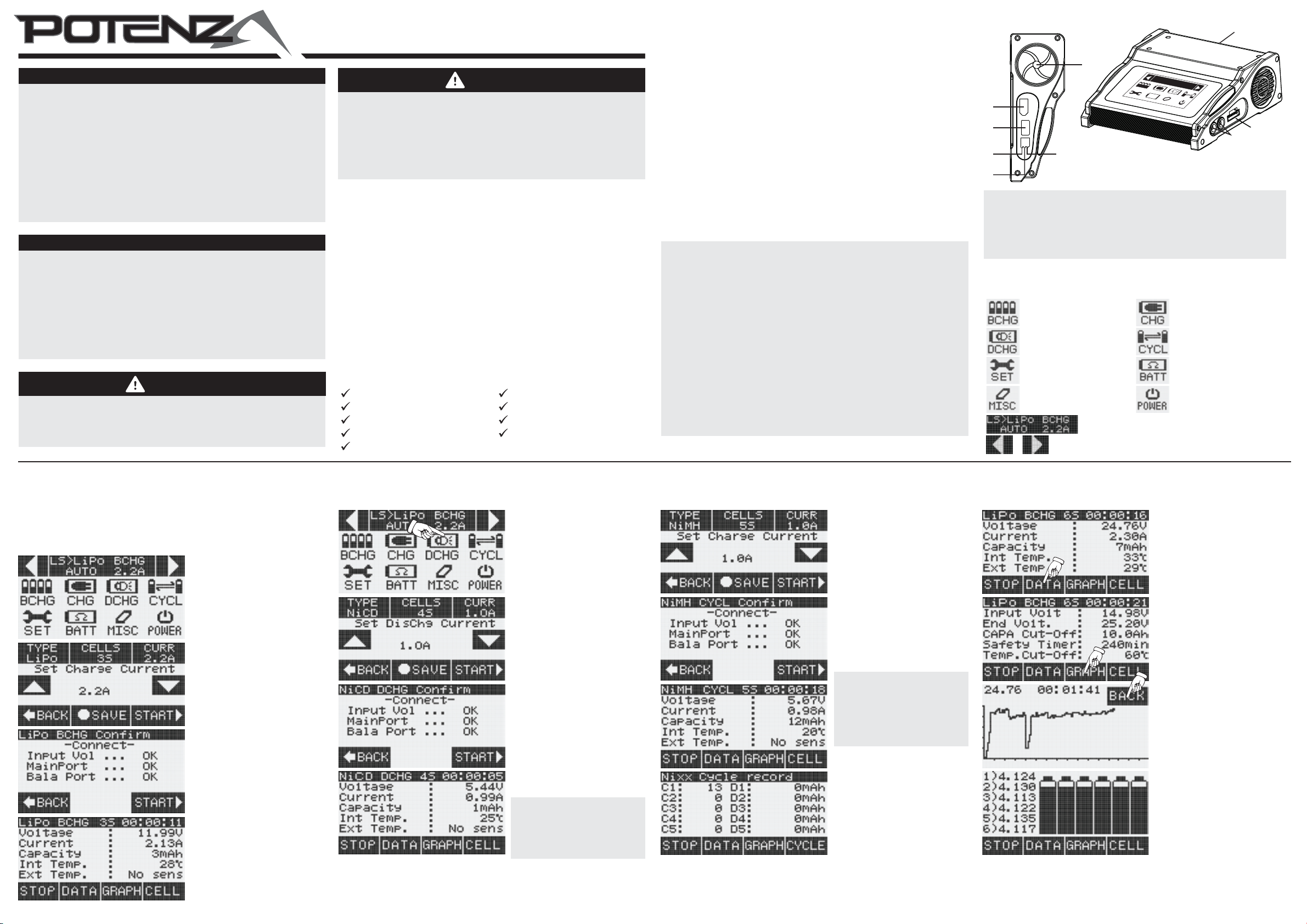
CHARGER LAYOUT
4
5
LS> L iPo C HG
6S 2. 2A
BCH G
CHG
SET
6
7
DCH G CYCL E
Ω
BATT
MIS C
POW ER
1
3
2
8
10
9
1. LCD Touch Screen 6. DC Power Input Port
2. 4.0mm Output Jacks 7. 5V/2.1A USB Output Port
3. JST-XH Balance Adapter Port 8. Servo/ESC PWM Output Port
4. AC Power Input Port 9. Temperature Sensor Port (optional)
5. Cooling Fan 10. Serial Bus Connection Port
HOME SCREEN ICONS
Pressing the corresponding icons on the screen will enter the charger into its various
modes and programs. The main icons used below enter the main function menus.
Balancing Charge Mode
Setup Mode
Miscellaneous Function
Enter current stored memory prole
Select stored memory prole
Normal Charging Mode
Battery Cycle ModeDischarge Mode
Battery Monitor Mode
Digital Power Mode
CHARGE MODE
Select the desired charging mode from the main menu. Balance charging (BCHG) is
only for LiXX chemistry packs and ensures that each cell in the battery is charged to
the same voltage and capacity for optimal performance and pack longevity.
Normal charge mode (CHG) does not employ the charger’s internal balance function
during charge. It is not recommended for LiXX batteries unless an external balancer
is used in conjunction with the charger.
1. If in balance charge mode, plug
the balance board into the
charger, then plug the battery’s
balance plug into the
corresponding port on the
balance board.
2. Connect the charge leads rst to
the charger, and then to the
battery. ENSURE CORRECT
CHARGE LEAD POLARITY.
3. Touch either the BCHG or CHG
icon on the home screen to enter
the desired charge function.
4. Touch the bars at the top of the
screen to set the battery type, cell
count, and current. Use the up
and down arrows to scroll
through the menu options for
each parameter.
5. Press START to conrm these
settings. Press START again to
initiate the charging process.
Once charging begins, the data
screen to the left will display
to provide live charging
parameter information.
6. Press STOP at any time to
terminate the charging process.
DISCHARGE MODE
Discharge mode serves to reduce the voltage of LiXX packs for safe long-term
storage as well as monitor battery health for NiXX and Pb battery chemistries.
1. Connect the charge leads rst to
the charger, and then to the
battery. ENSURE CORRECT
CHARGE LEAD POLARITY.
2. Touch the DCHG icon on the
home screen to enter the
discharge function.
3. Touch the bars at the top of the
screen to set the battery type, cell
count, and current. Use the up
and down arrows to scroll
through the menu options for
each parameter.
4. Press START to conrm these
settings. Press START again to
initiate the discharge process.
Once discharging begins, the
data screen to the left will
display to provide live discharge
parameter information.
5. Press STOP at any time to
terminate the discharging
process.
NOTE: The discharge mode will
give battery’s capacity from a
full charge (including LiXX),
similar to a single cycle of the
battery.
BATTERY CYCLE MODE (NiXX ONLY)
Use the cycle mode to complete a full discharge and recharge cycle to determine
the capacity and health of NiCd and NiMH packs.
1. Connect the charge leads rst to
the charger, and then to the
battery. ENSURE CORRECT
CHARGE LEAD POLARITY.
2. Touch the C YCL icon on the
home screen to enter the
discharge function.
3. Touch the bars at the top of the
screen to set the battery type, cell
count, and current. Use the up
and down arrows to scroll
through the menu options for
each parameter.
NOTE: Verify the proper cycle
(charge/discharge) is selected
in the user setup menu. The rst
cycle defaults to charge to
guard against permanent
damage to the battery pack.
4. Press START to conrm these
settings. Press START again to
initiate the discharge process.
Once discharging begins, the
data screen to the left will
display to provide live discharge
parameter information.
5. Press CYCLE to view the results of
each cycle.
6. Press STOP at any time to
terminate the cycle process.
ADDITIONAL CHARGING DATA
In each of the three previous modes, additional battery data is available to measure
the performance and health of your battery.
1. From the charging or discharge
process screen, utlize DATA,
GRAPH, and CELL buttons at any
time for detailed information.
2. Press DATA for in-depth metrics
about the process prole that is
active. Press DATA again to return
to the normal process screen.
3. Press the GRAPH button to view a
graphical depiction of the
battery’s total voltage over time.
Current cell voltage and elapsed
time are displayed along the top.
Press “BACK” to return to the
previous screen.
5. Press the CELL button from any
screen to view the individual cell
voltages for the battery in
process. THIS FUNCTION IS NOT
APPLICABLE TO BATTERY CYCLE
MODE, ONLY BALANCE CHARGE,
CHARGE, AND DISCHARGE.

CHARGER SETUP MODE
Ensure correct polarity correction between power
supply and charger, and charger and battery.
PROCESS INTERRUPTED
Ensure all power connections are correct.
Output short circuit. Break all battery connections
damage.
Input voltage outside of normal range. Ensure that
input voltage is between 11.0 and 18.0v.
CHARGER FAILURE
Charger electronics require repair.
Battery voltage is lower than value setting in
battery is not damaged.
Battery voltage is higher than value setting in
battery is not damaged.
Individual lithium cell voltage too low. Pack may
be damaged; inspect and/or replace pack.
Individual lithium cell voltage too high. Pack may
be damaged; inspect and/or replace pack.
Balance port connection error. Ensure that balance
battery; if correct, inspect for pack damage.
Disconnect battery, power o charger and allow
to cool for a minimum of 20 minutes.
-OVER POWER-
Power exceeded In digital power mode.
Current exceeded in digital power mode.
Maximum safe charge time limit exceeded. Ensure
correct charger conguration and restart charging.
Maximum battery capacity limit exceeded. Break
location for monitoring.
External temperature exceeded. Break all charging
connections, power o, and allow battery to cool.
LiPo
LiFe
Li-Ion
NiMH
NiCd
Pb
Standard Voltage (volts per cell)
3.70
3.30
3.60
1.20
1.20
2.00
Maximum Voltage (volts per cell)
4.20
3.60
4.10
1.60
1.60
2.45
Minimum Voltage (volts per cell)
3.00
2.00
3.00
1.00
0.85
1.75
The charger setup menu allows full customization of every parameter within the
charger from the interface (contrast, lighting, sounds) to specic parameters related
to the performance of the charger and its various battery program settings.
Once in the menu, to select an item, simply press it. The BACK and NEXT buttons
scroll through the pages, and the up and down arrows increase or decrease values
for the highlighted selection. Touch the SET icon on the home screen to enter the
charger setup menus.The ranges for setting values are as follows:
20-80%
30-60
on/o
on/o
50-80W
10.0-14.0VDC
10-600 min
50-80°C
50-80°C
500mAh-50Ah
CD/CD
1-5 cycles
5-60 min
5-25mV
5-25mV
4.00-4.25V
3.00-4.00V
3.50-3.70V
1.80-3.30V
2.00-2.50V
1.20-2.00V
0.80-1.50V
0.50-1.50V
4.00-4.15V
3.00-3.90V
SAVE CHARGING PROFILE
There are 18 memory slots available to store charge settings, 8 (M11-M18) of which
are customizable by the user. These can be recalled from the main menu without
having to congure settings every time.
1. When in the charging setup
menu, save current charger
conguration settings by
pressing SAVE instead of START.
2. Navigate to the desired memory
bank, and press SAVE again to
commit the prole to that
memory slot.
NOTE: On the home screen, the
letters LS in the memory select
ribbon denotes “last selected”.
This means that the memory
item preceded by LS was the
last memory item used.
From the home screen, use the
left and right arrows to navigate
the memory proles. Once the
desired selection is visible, press
the bar to enter the conguration.
BATTERY MONITOR MODE (LiXX ONLY)
View individual cell resistance and voltage parameters.
1. Touch the B ATT icon on the
home screen to enter the battery
monitor menu.
2. Select the appropriate lithium
battery chemistry to properly
display the data by pressing the
second button on the bottom
row. The cell type defaults to LiPo.
3. Press the IR icon to view each
cell’s internal resistance.
4. Press the BALA icon to balance
the cells. The process will stop
automatically when nished.
Press STOP at any point to abort
the process.
5. Press BACK to exit back to the
main charging menu.
ADDITIONAL FUNCTIONS
In addition to normal charging functions, the Potenza C80 features standard
5W/2.1A USB power output and PWM output functions.
1. Touch the MISC icon on the
home screen to enter the USB
power and PWM test output
function sub-menu.
2. Press the USB icon to view the
USB monitor page. Power is
applied automatically when a
USB cable is connected to the
port. Press BACK to exit to the
previous sub menu.
NOTE: It is not necessary to be
in this menu for the USB port to
power a connected device. This
function is for monitoring only.
3. Press the SERVO icon to view the
PWM output test page.
Touch MAX OUT PPM and MIN
OUT PPM to restrict the upper
and lower limits, using the up and
down arrows to change the
output value for each.
Press the current output value
towards the bottom to adjust the
actual pulse width output.
Press AUTO to enter an
automatic sweep between the
MAX and MIN values. Press MANU
to return to manual mode and
EXIT to exit to the previous menu.
DIGITAL POWER MODE
In digital power mode, the charger can provide 1.0V-28.0VDC output power through
the 4.0mm jacks with a maximum output of 80W.
1. Touch the POWER icon on the
home screen to enter the digital
power mode menu.
2. Touch each of the menu options
to select, and use the up and
down arrows to increase or
decrease their values. Ranges are:
VOLTAGE OUTPUT: 1.0-28.0V
CURRENT: 1.0A-10.0A
MAX WATTAGE: 10-80W
RUN TIME: 1-600 min
3. Press START to save the settings
and begin digital power mode
WARNING
The programmable power supply mode should not be used to directly charge
batteries of ANY chemistry. Improper use will cause excessive heat or FIRE.
Failure to comply may result in excessive heat, re, damage to property and
serious personal injury.
TROUBLESHOOTING GUIDE
Error Message Possible Cause/Recommended Action
REVERSE POLARITY
OUTPUT SHORT CIRCUIT
and examine charge leads and battery for
INPUT VOLTAGE ERROR
BATTERY LOW VOLTAGE
BATTERY HIGH VOLTAGE
charger for type. Adjust settings and ensure
charger for type. Adjust settings and ensure
CELL LOW VOLTAGE
CELL HIGH VOLTAGE
-
CELL CONNECT ERROR
leads are connected properly to charger and
CHARGER OVERHEATING
-MAX CURRENT-
-SAFETY TIMER-
-MAX CAPACITY-
all charging connections and set battery in a safe
-MAX EXT. TEMP-
BATTERY VOLTAGE REFERENCE TABLE
Battery Type
FCC CLASS B NOTICE
This device complies with Part 15 of the FCC Rules. Operation is subject to the
following two conditions:
1. This device may not cause harmful interference.
2. This device must accept any interference received, including interference that
may cause undesired operation.
This equipment has been tested and found to comply with the limits for a Class B
digital device, pursuant to Part 15 of the FCC Rules. These limits are designed to
provide reasonable protection against harmful interference in a residential
installation. This equipment generates, uses and can radiate radio frequency energy
and, if not installed and used in accordance with the instructions, may cause
harmful interference to radio communications. However, there is no guarantee that
interference will not occur in a particular installation.
Modications: Any modications made to this device that are not approved by
Flex Innovations, Inc. may void the authority granted to the user by the FCC to
operate this equipment.
LIMITED WARRANTY
Warranty Coverage - Flex Innovations, Inc. and its authorized resellers (“Flex”)
warrant to the original purchaser that the product purchased (the “Product”) it will be
free from defects in materials and workmanship at the date of purchase.
Outside of Coverage - This warranty is not transferable and does not cover: (i)
Products with more than 45 days after purchased date; (ii) Damage due to acts of
God, accident, misuse, abuse, negligence,commercial use, or due to improper use,
installation, operation or maintenance; (iii) Modication of or to any part of the
Product; (iv) Product not compliant with applicable technical regulations; (v)
Shipping damage; (vi) Cosmetic damage
OTHER THAN THE EXPRESS WARRANTY ABOVE, FLEX MAKES NO OTHER WARRANT Y
OR REPRESENTATION, AND HEREBY DISCLAIMS ANY AND ALL IMPLIED WARRANTIES,
INCLUDING, WITHOUT LIMITATION, THE IMPLIED WARRANTIES OF NONINFRINGEMENT, MERCHANTABILIT Y AND FITNESS FOR A PARTICULAR PURPOSE. THE PURCHASER ACKNOWLEDGES THAT THEY ALONE HAVE DETERMINED THAT THE PRODUCT WILL
SUITABLY MEET THE REQUIREMENTS OF THE PURCHASER’S INTENDED USE.
Purchaser’s Solution - Flex’s sole obligation and purchaser’s sole and exclusive
remedy shall be that Flex will, at its option, either (i) service, or (ii) replace, any
Product determined by Flex to be defective. Flex reserves the right to inspect any and
all Product(s) involved in a warranty claim. Service or replacement decisions are at the
sole discretion of Flex. Proof of purchase is required for all warranty claims. SERVICE
OR REPLACEMENT AS PROVIDED UNDER THIS WARRANTY IS THE PURCHASER’S
SOLE AND EXCLUSIVE REMEDY.
Limitation of Liability - FLEX SHALL NOT BE LIABLE FOR SPECIAL, INDIRECT,
INCIDENTAL OR CONSEQUENTIAL DAMAGES, LOSS OF PROFITS OR PRODUCTION OR
COMMERCIAL LOSS IN ANY WAY, REGARDLESS OF WHETHER SUCH CLAIM IS BASED IN
CONTRACT, WARRANTY, TORT, NEGLIGENCE, STRICT LIABILITY OR ANY OTHER
THEORY OF LIABILITY, EVEN IF FLEX HAS BEEN ADVISED OF THE POSSIBILITY OF SUCH
DAMAGES.
Further, in no event shall the liability of Flex exceed the individual price of the
Product on which liability is asserted. As Flex has no control over use, setup,
assembly, modication or misuse, no liability shall be assumed nor accepted for any
resulting damage or injury. By the act of use, setup or assembly, the user accepts all
resulting liability. If you as the purchaser or user are not prepared to accept the
liability associated with the use of the Product, purchaser is advised to return the
Product immediately in new and unused condition to the place of purchase.
Law - These terms are governed by Florida law (without regard to conict of law
principals). This warranty gives you specic legal rights, and you may also have other
rights which vary from state to state. FLEX RESERVES THE RIGHT TO MODIFY THIS
WARRANTY AT ANY TIME WITHOUT PRIOR NOTICE.
Questions & Assistance - For customer support in your region, visit:
http://www.exinnovations.com/index.php/reseller-sub
Inspection or Services - If this Product needs to be inspected or serviced and is
compliant in the region you live and use the Product in, please contact your regional
Flex authorized reseller. Pack the Product securely using a shipping carton. Please
note that original boxes needs to be included, but are not designed to withstand the
rigors of shipping without additional protection. Ship via a carrier that provides
tracking and insurance for lost or damaged parcels, as Flex is not responsible for
merchandise until it arrives and is accepted at our facility.
Warranty Requirements - For Warranty consideration, you must include your
original sales receipt verifying the proof of purchase date. Provided warranty
conditions have been met, your Product will be replaced free of charge. Shipping
charges are as follow: to Flex by customer, Flex out it is by Flex. Service or replacement decisions are at the sole discretion of Flex.
COMPLIANCE INFORMATION FOR THE EUROPEAN UNION
Declaration of Conformity (In accordance with ISO/IEC 17050-1)
Product(s):
Item Number(s): FPZC0080
The object of declaration described above is in conformity with the requirements of the
specications listed below, following the provisions of the EMC Directive 2004/108/EC,
LVD Directive 2006/95/EC and RoHS 2011/65/EU Annex II:
EN 55014-1:2006+A1:2009+A2:2011;
EN 55014-2:1997+A1:2001+A2:2008;
EN 61000-3-2:2006+A1:2009+A2:2009;
EN 61000-3-3:2008
EN 60335-1:2012;
EN 60335-2-29:2004+A2:2010;
EN 62233:2008
Instructions for disposal of WEEE by users in the European Union
This product must not be disposed of with other waste. Instead, it is the
user’s responsibility to dispose of their waste equipment by handing it over
to a designated collections point for the recycling of waste and electronic
equipment. The sepearate collection and recycling of your waste equipment
at the time of disposal will help to conserve natural resources and ensure
that it is recycled in a manner that protects human health and the
environment. For more information about where to drop o your waste
equipment for recycling, please contact your local city oce, your household
waste disposal service or where you purchased the product.
Potenza C80 AC/DC 80 Watt Multi-Chemistry Charger
Premier Aircraft™,Potenza™, and Top Value RC™ are trademarks
or registered trademarks of Flex Innovations, Inc.
© 2014 Flex Innovations, Inc.
INNOVATIONS
Created 12/2014
TM
 Loading...