

Page 1
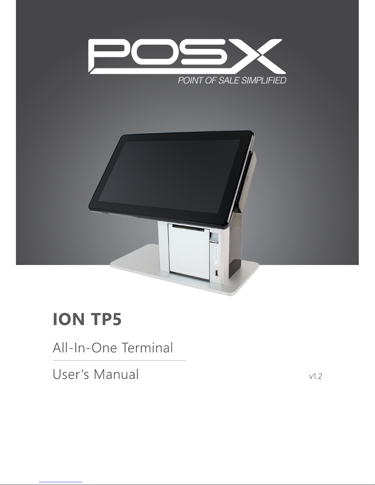
ION TP5
All-In-One Terminal
User’s Manual
v1.2
Page 2

ii
Copyright 2015
All Rights Reserved
Manual Version 1.2
Part Number: TP5
The information contained in this document is subject to change without notice.
We make no warranty of any kind with regard to this material, including, but not limited
to, the implied warranties of merchantability and fitness for a particular purpose.
We shall not be liable for errors contained herein or for incidental or consequential
damages in connection with the furnishing, performance, or use of this material.
This document contains proprietary information that is protected by copyright. All rights
are reserved. No part of this document may be photocopied, reproduced or translated
to another language without the prior written consent of the manufacturer.
TRADEMARK
I
ntel®, Pentium® and MMX are registered trademarks of Intel® Corporation.
Microsoft® and Windows® are registered trademarks of Microsoft Corporation.
Other trademarks mentioned herein are the property of their respective owners.
Safety
IMPORTANT SAFETY INSTRUCTIONS
1. To disconnect the machine from the electrical power supply, shut the terminal down
and remove the power cord plug from the wall socket. The wall socket must be easily
accessible and in close proximity to the machine.
2. Read these instructions carefully. Save these instructions for future reference.
3. Follow all warnings and instructions marked on the product.
4. Do not use this product near water.
5. Do not place this product on an unstable cart, stand, or table. The product may fall,
causing injury or serious damage to the product.
6. Slots and openings in the cabinet and the back or bottom are provided for ventilation
to ensure reliable operation of the product and to protect it from overheating. These
openings must not be blocked or covered. The openings should never be blocked by
placing the product on a bed, sofa, rug, or other similar surface. This product should
never be placed near or over a radiator or heat register or in a built-in installation
unless proper ventilation is provided.
7. This product should be operated from the type of power indicated on the electrical
safety label. If you are not sure of the type of power available, consult your dealer or
local power company.
8. Do not allow anything to rest on the power cord. Do not place this product where
persons will walk on the cord.
9. Never push objects of any kind into this product through cabinet slots as they may
touch dangerous voltage points or short out parts that could result in a re or electric
shock. Never spill liquid of any kind on the product.
Page 3
iii
CE MARK
This device complies with the requirements of the EEC directive 2004/108/EC with
regard to “Electromagnetic compatibility” and 2006/95/EC “Low Voltage Directive”.
FCC
This device complies with part 15 of the FCC rules. Operation is subject to the following
two conditions:
(1) This device may not cause harmful interference.
(2) This device must accept any interference received, including interference that may
cause undesired operation.
CAUTION ION LITHIUM BATTERIES
There is a danger of explosion if the battery is replaced incorrectly. Replace only
with the same or equivalent type recommended by the manufacturer. Discard used
batteries according to the manufacturer’s instructions.
Battery Caution
Risk of explosion if battery is replaced by an incorrectly type. Dispose of used battery
according to the local disposal instructions.
Safety Caution
Note: To comply with IEC60950-1 Clause 2.5 (limited power sources, L.P.S) related
legislation, peripherals shall be 4.7.3.2 “Materials for re enclosure” compliant.
4.7.3.2 Materials for re enclosures
For MOVABLE EQUIPMENT having a total mass not exceeding 18kg.the material of a
FIRE ENCLOSURE, in the thinnest signicant wall thickness used, shall be of V-1 CLASS
MATERIAL or shall pass the test of Clause A.2.
For MOVABLE EQUIPMENT having a total mass exceeding 18kg and for all STATIONARY
EQUIPMENT, the material of a FIRE ENCLOSURE, in the thinnest significant wall
thickness used, shall be of 5VB CLASS MATERIAL or shall pass the test of Clause A.1
Page 4

iv
LEGISLATION AND WEEE SYMBOL
2012/19/EU Waste Electrical and Electronic Equipment Directive on the treatment,
collection, recycling and disposal of electric and electronic devices and their
components.
The crossed dust bin symbol on the device means that it should not be disposed of
with other household wastes at the end of its working life. Instead, the device should
be taken to the waste collection centers for activation of the treatment, collection,
recycling and disposal procedure.
To prevent possible harm to the environment or human health from uncontrolled waste
disposal, please separate this from other types of wastes and recycle it responsibly to
promote the sustainable reuse of material resources.
Household users should contact either the retailer where they purchased this product,
or their local government ofce, for details of where and how they can take this item for
environmentally safe recycling.
Business users should contact their supplier and check the terms and conditions of
the purchase contract.
This product should not be mixed with other commercial wastes for disposal.
Page 5

v
USER INFORMATION REQUIREMENTS
Products shall be shipped with informational materials to notify customers of the
following:
1. A description of power management settings that have been enabled by default.
2. A description of the timing settings for various power management features
and instructions for properly waking the product from Sleep Mode.
Products shall be shipped with one or more of the following:
1. A list of default power management settings.
2. A note stating that default power management settings have been selected for
compliance with ENERGY STAR (within 15 min of user inactivity for the dis play, within 30 min for the computer, if applicable per Table2), and are recom-
mended by the ENERGY STAR program for optimal energy saving.
3. Information about ENERGY STAR and the benets of power management, to
be located at or near the beginning of the hard copy or electronic user manual,
or in a package or box insert.
The power management feature allows the computer to initiate a low-power or
“Sleep” mode after a period of user inactivity. When used with an external
ENERGY STAR qualied monitor, this feature also supports similar power
management features of the monitor. To take advantage of these potential energy
savings, the power management feature can be set to behave in the following
ways when the system is operating on AC power.
● Turn off the display after 15 minutes.
● Initiate Sleep after 30 minutes.
Page 6

vi
Revision History
Changes to the original user manual are listed below:
Revision Description Date
1.0 • Initial release July 2015
1.1
• Instruction on locking the back cover added
• Instruction on installing the LCM module added
April 2016
1.2
• Rear 8” LCD installation instructions and specications added
September 206
Page 7

vii
Table of Contents
1. Packing List .............................. 1
1-1. Standard Accessories ..............................................1
1-2. Optional Accessories ............................................... 2
2. System View ............................. 3
2-1. Front View ...............................................................3
2-2. Side View ................................................................. 5
2-3. IO Port View ............................................................6
3. Assembly & Disassembly ....... 7
3-1. Unlocking the Back Cover .......................................7
3-2. Removing the Rear Housing ...................................7
3-3. Installing the Power Adapter .................................... 8
3-4. Dimensions .............................................................. 9
4. Peripheral Installation ............ 10
4-1. Installing the MSR .................................................10
4-2. Installing the LCM Module ...................................... 11
4-3. Loading the Thermal Printer Paper ........................12
4-4. Installing the Rear LCD Module ..............................13
5. Specications ......................... 14
Page 8

viii
6. Jumper Settings ...................... 16
6-1. Printer Board Settings ............................................16
Appendix: Driver Installation ...... 17
Page 9

ix
The page is intentionally left blank.
Page 10
1
1. Packing List
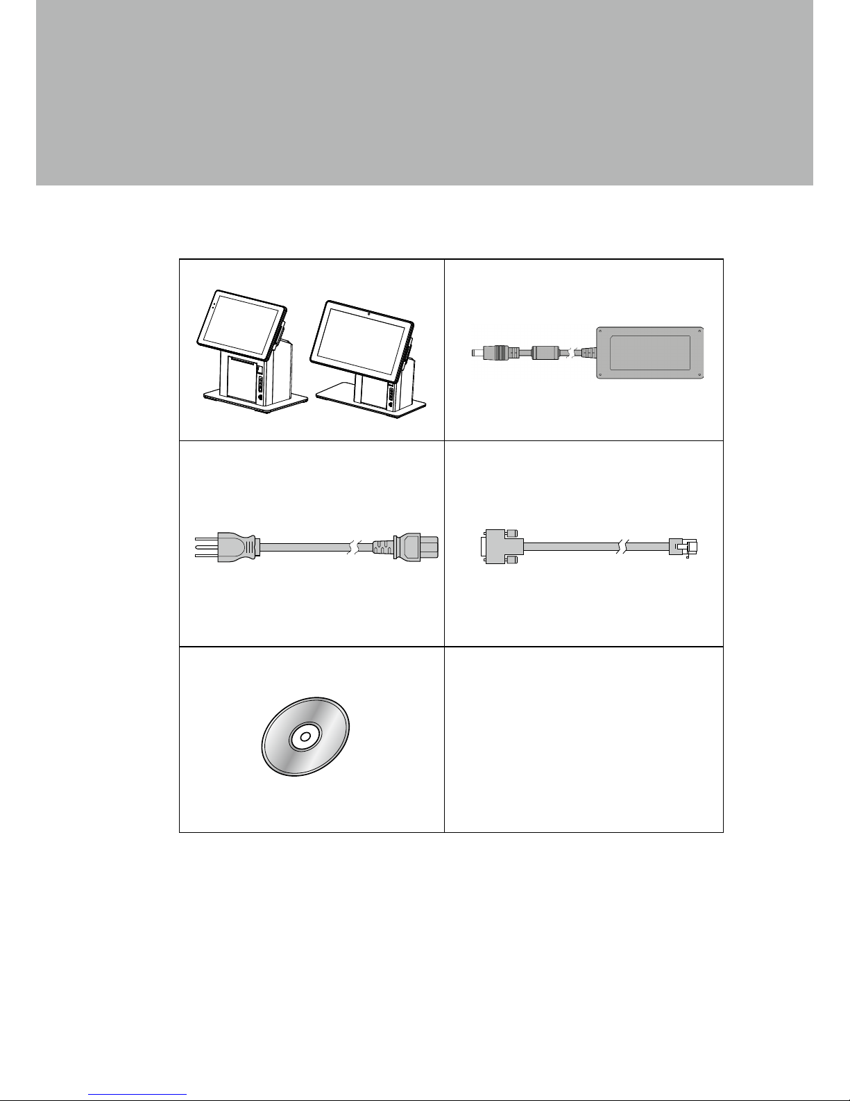
1-1.
Standard Accessories
a. TP5 System
b. Power adapter
c. Power cord
d. RJ45-DB9 cable (x1)
e. Driver CD
a
b
c
d
e
Page 11
2
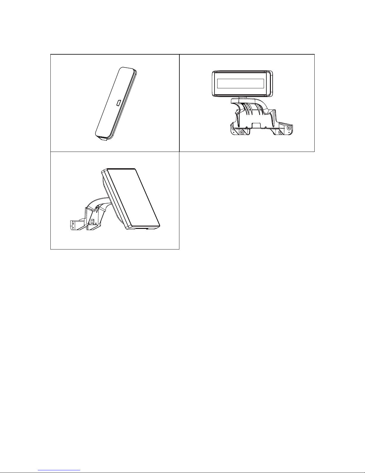
1-2.
Optional Accessories
a. MSR module
b. LCM module
c. Rear LCD module
a
b
c
Page 12
3
3
2
1
4
5
2. System View
2-1.
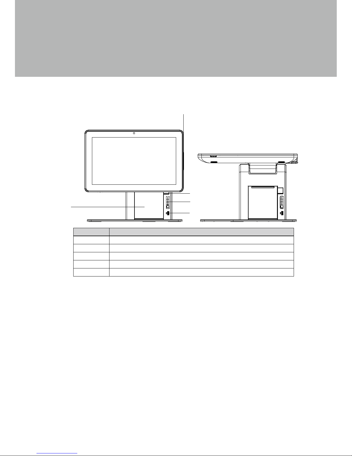
Front View
TP5E
Item No. Description
1 MSR module
2 Thermal printer open door button
3 Thermal printer
4 Printer indicator(power, error, and paper) & Paper feed button
5 USB
View angle of 0 degrees
Page 13
4
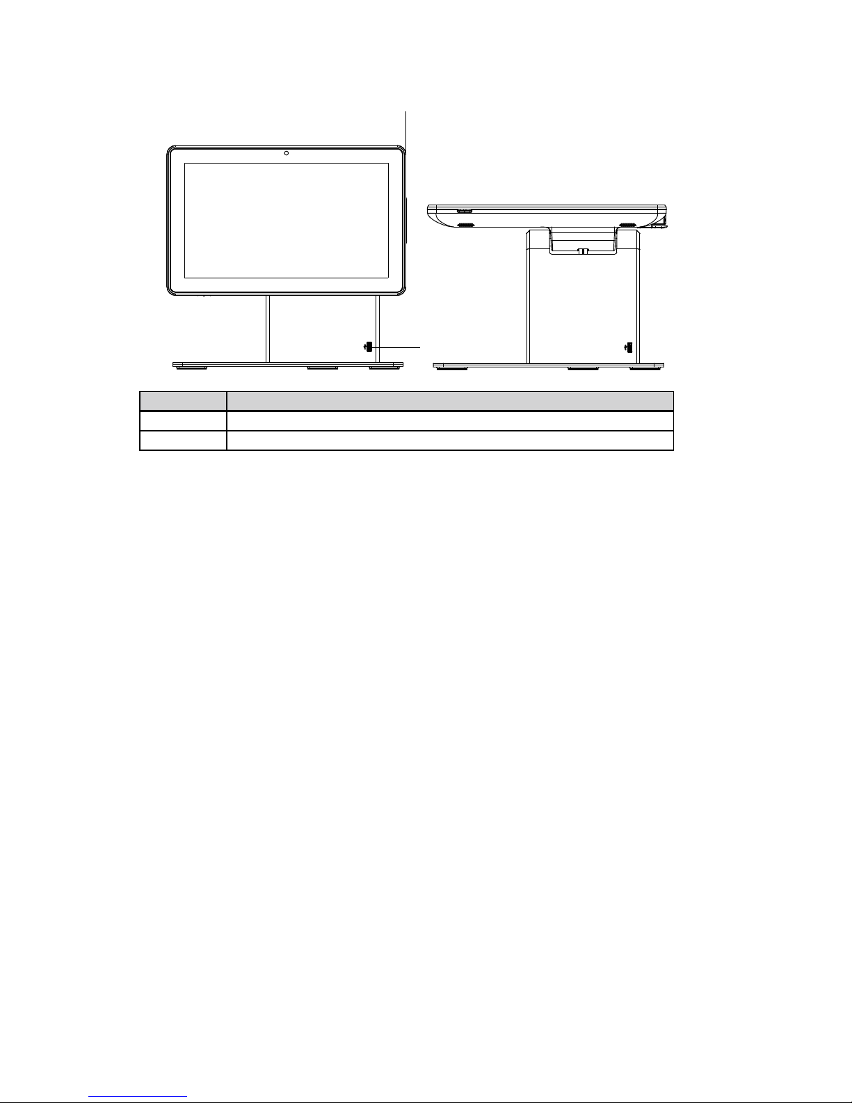
TP5F
Item No. Description
1 MSR module
2 USB
View angle of 0 degrees
2
1
Page 14
5
2-2.
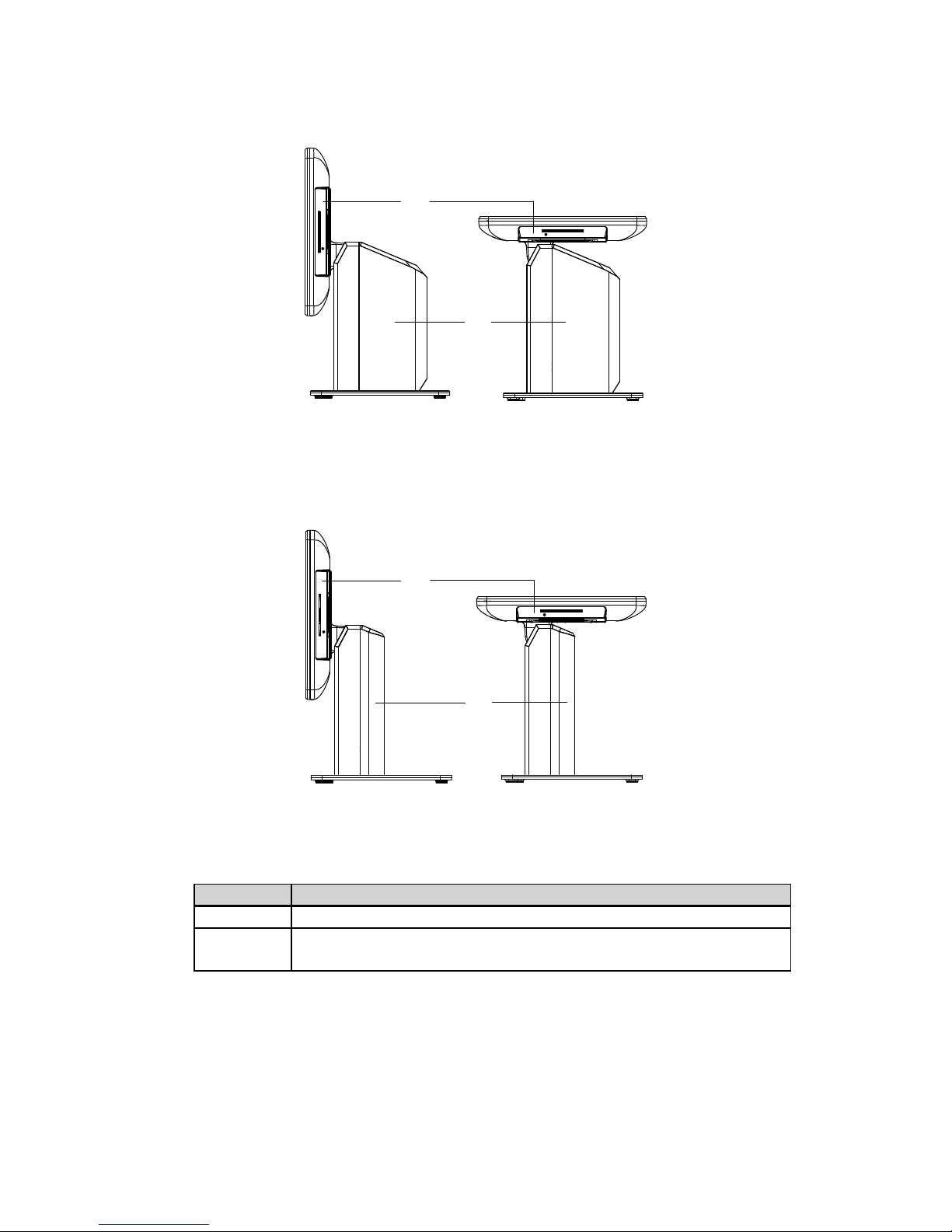
Side View
TP5E
1
2
Item No. Description
1 MSR module
2
System cover
(IO board and thermal printer inside on TP5E)
TP5F
1
2
Page 15
6
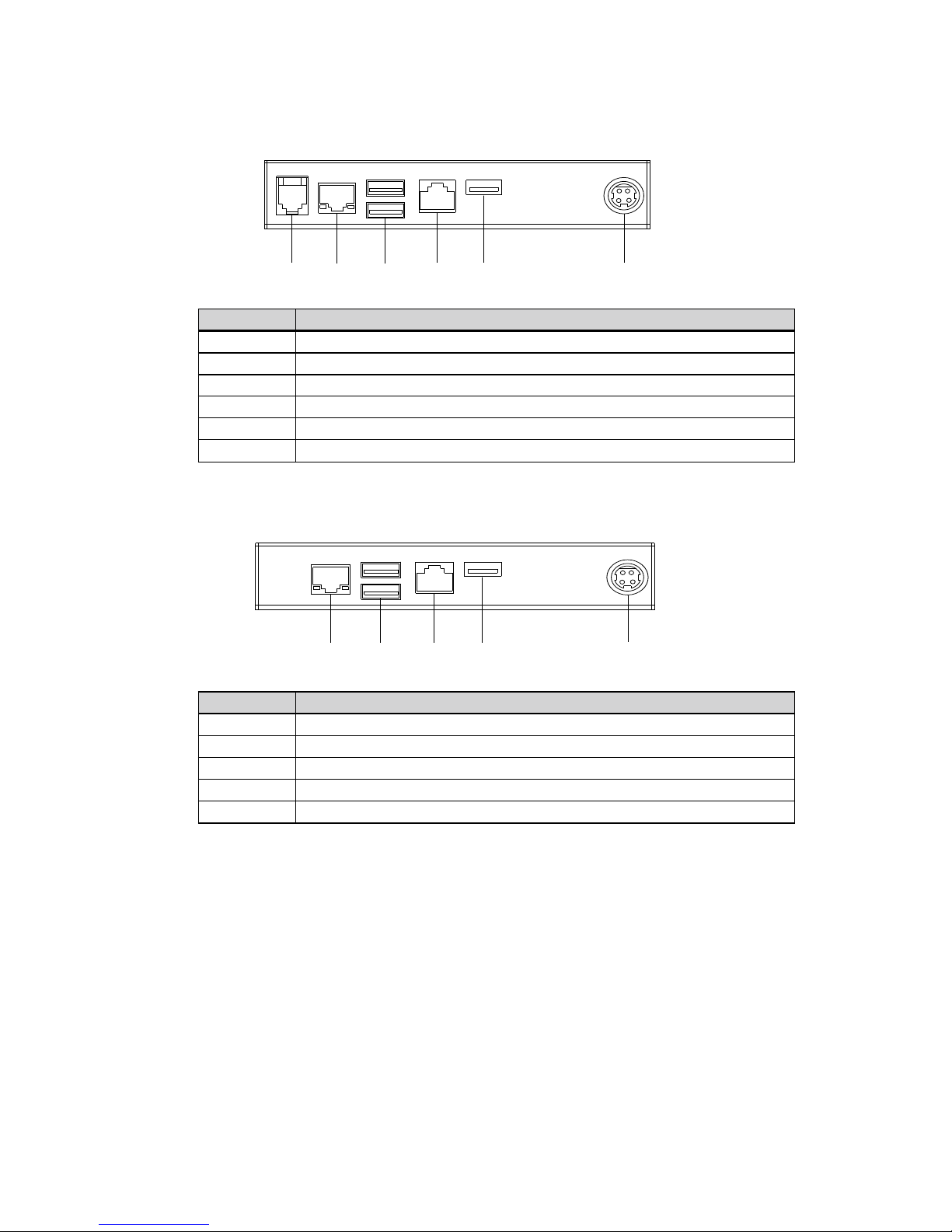
Item No. Description
a Cash Drawer
b LAN
c USB 2.0 (x2)
d COM port
e USB 2.0
f DC 19V in
2-3.
IO Port View
TP5E
Item No. Description
a LAN
b USB 2.0 (x2)
c COM port
d USB 2.0
e DC 19V in
a b c d e
TP5F
a b c d e f
Page 16
7
2-4.
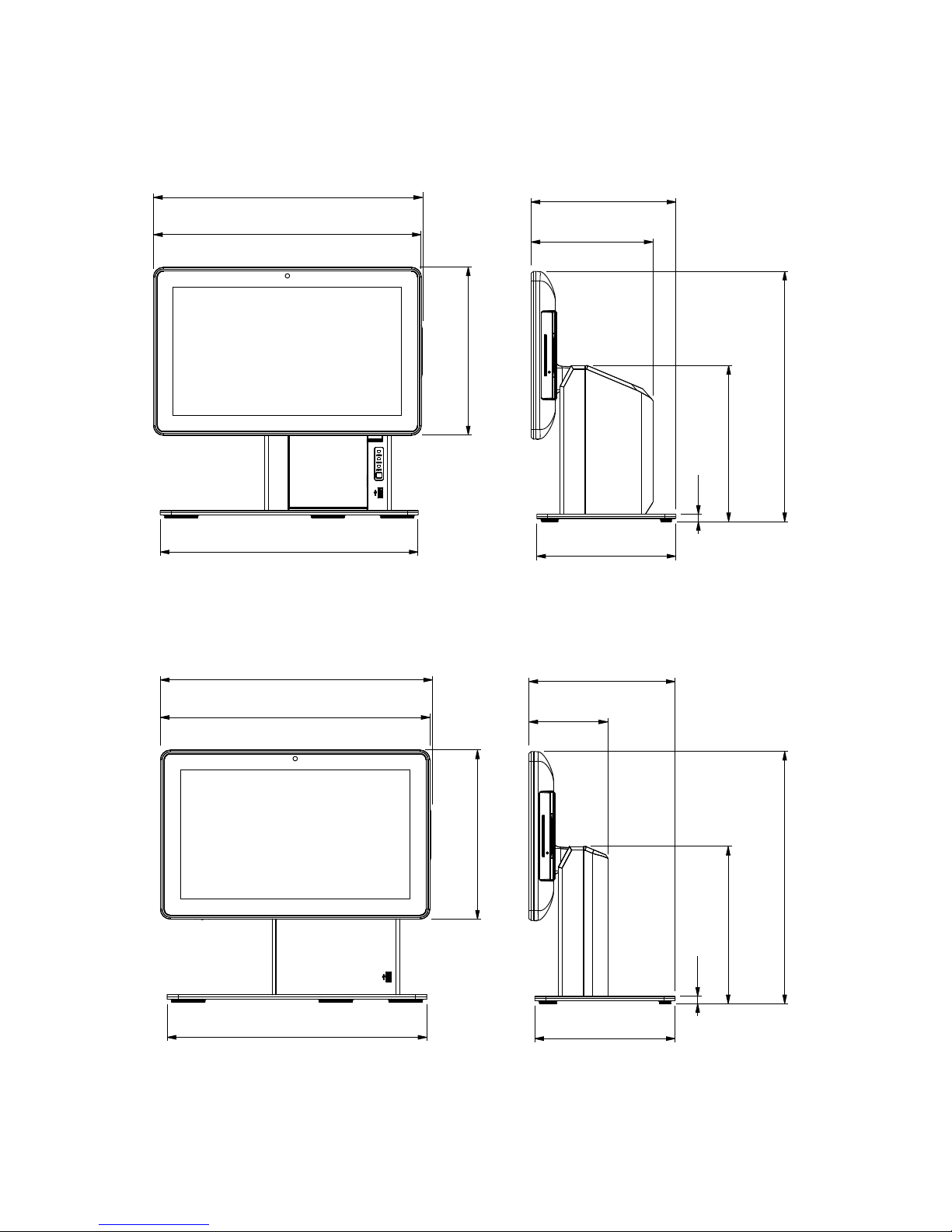
Dimensions
TP5E
227.8 mm
350 mm
370.6 mm
363.3 mm
10 mm
211.8 mm
339.7 mm
196.6 mm
165 mm
188.9 mm
TP5F
10 mm
211.8 mm
339.7 mm
196.6 mm
105 mm
188.9 mm
227.8 mm
350 mm
365.6 mm
363.3 mm
Page 17
8
3. Assembly & Disassembly
3-1.
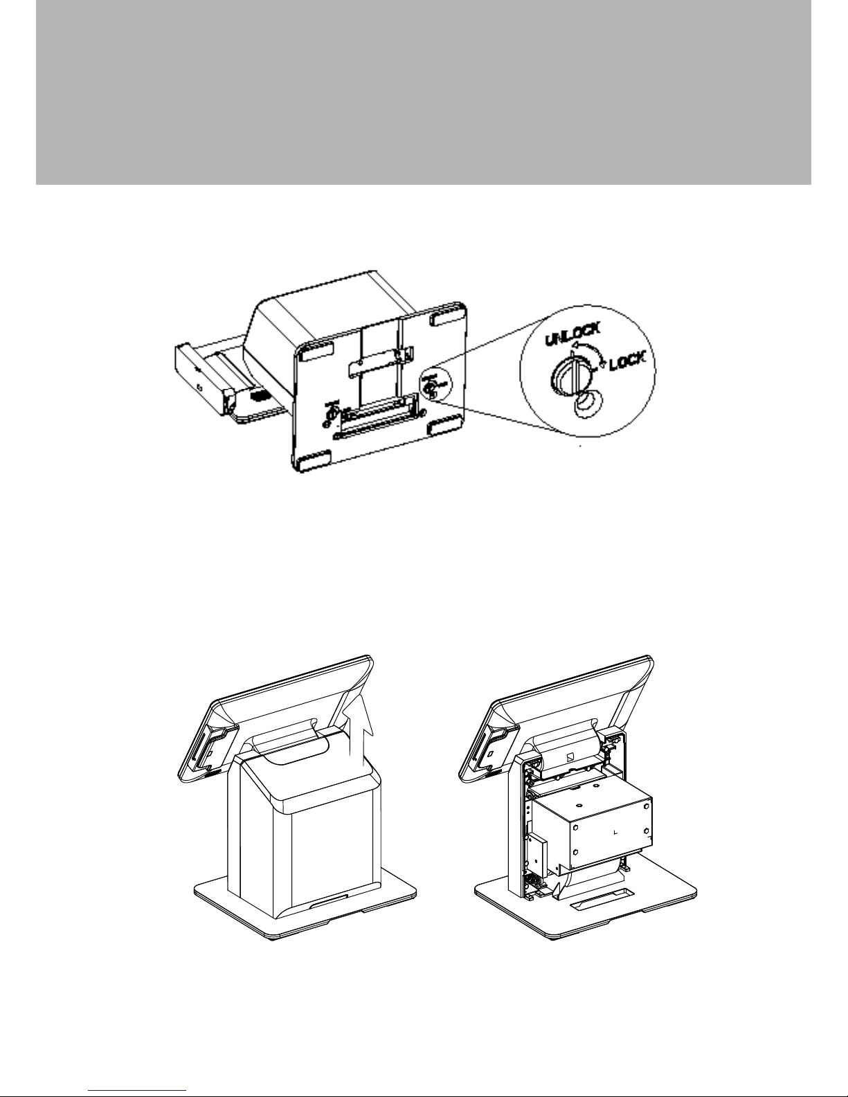
Unlocking the Back Cover
1. Use both hands to pull the system cover upward to release the cover from the
system.
3-2.
Removing the Rear Housing
1. On some models the back cover of the system is secured by two locking screws
which are located at the bottom of the stand.
2. To open the back cover, place the system face down, Insert a flat head screwdriver
or a small coin into the groove of the screw and turn to the Unlock position to
unlock.
3. To lock the system, turn the screw to the lock position.
Page 18
9
3-3.
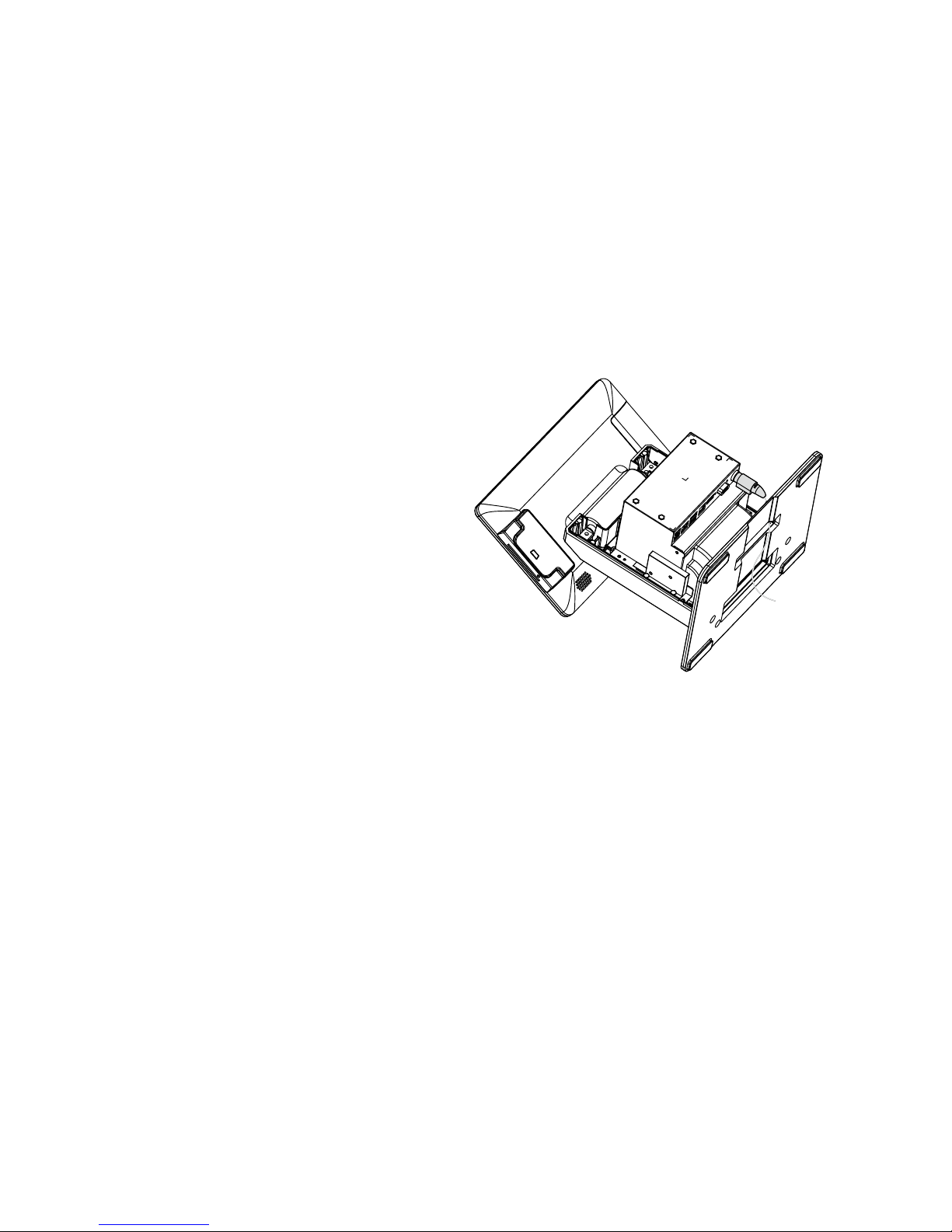
Installing the Power Adapter
The system is equipped with a 90W power adapter. Please connect it to the system
as shown below.
1. Follow the steps decribed in
Chapter 3-1 to remove the rear
housing.
2. Place the system face down to
access the bottom of the stand.
3. Thread the power adapter cable
through the hole of the stand as
shown in the picture.
4. Find the power connector on the
right of the I/O panel (refer to
chapter 2-4) and connect the
power adapter directly to the DCIN connector.
Page 19
10
4. Peripheral Installation
4-1.
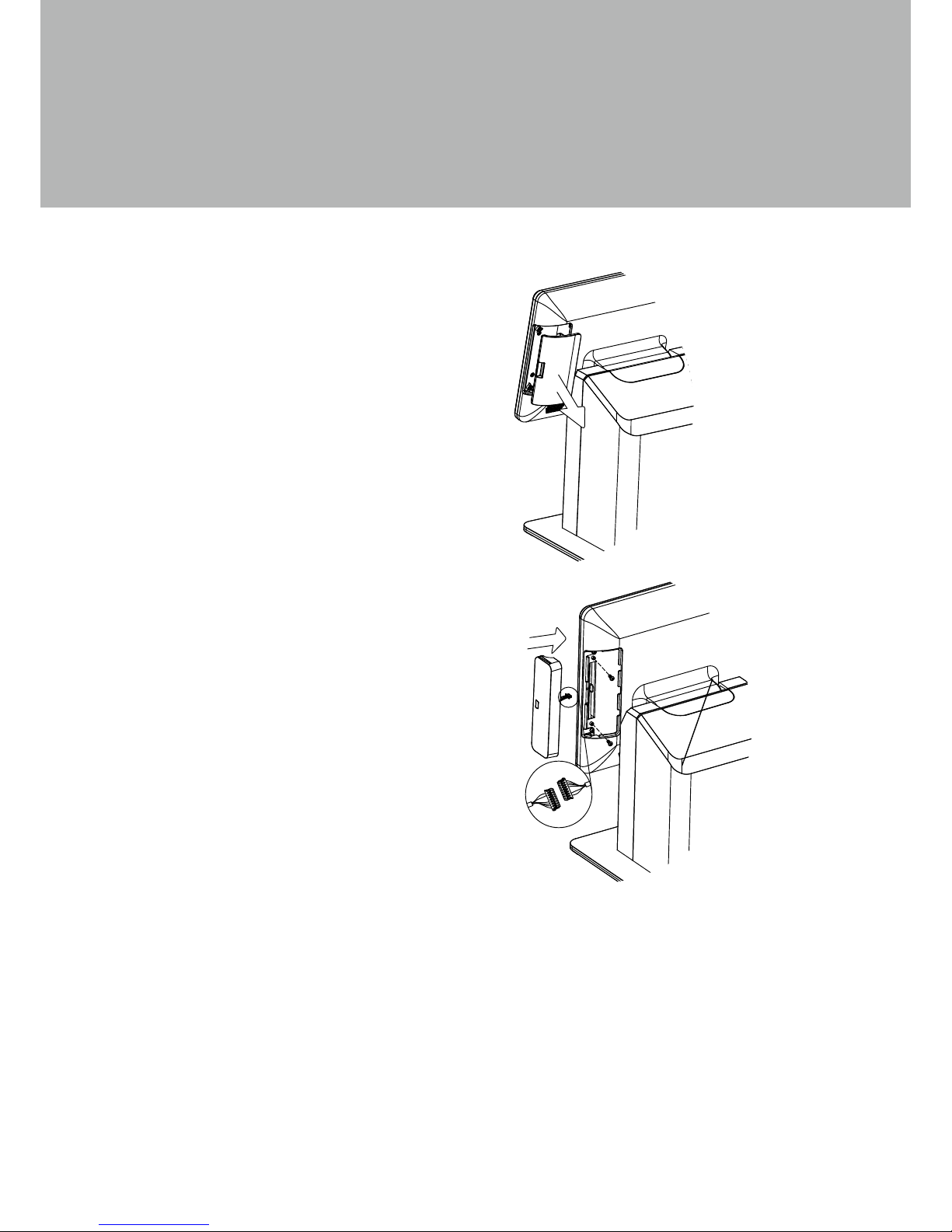
Installing the MSR
2. Connect the MSR cable to the connector
on the system side.
3. Put the MSR module in place and
fasten the screws (x2) on the back to
secure the module.
1. Remove the dummy cover.
Page 20
11
4-2.
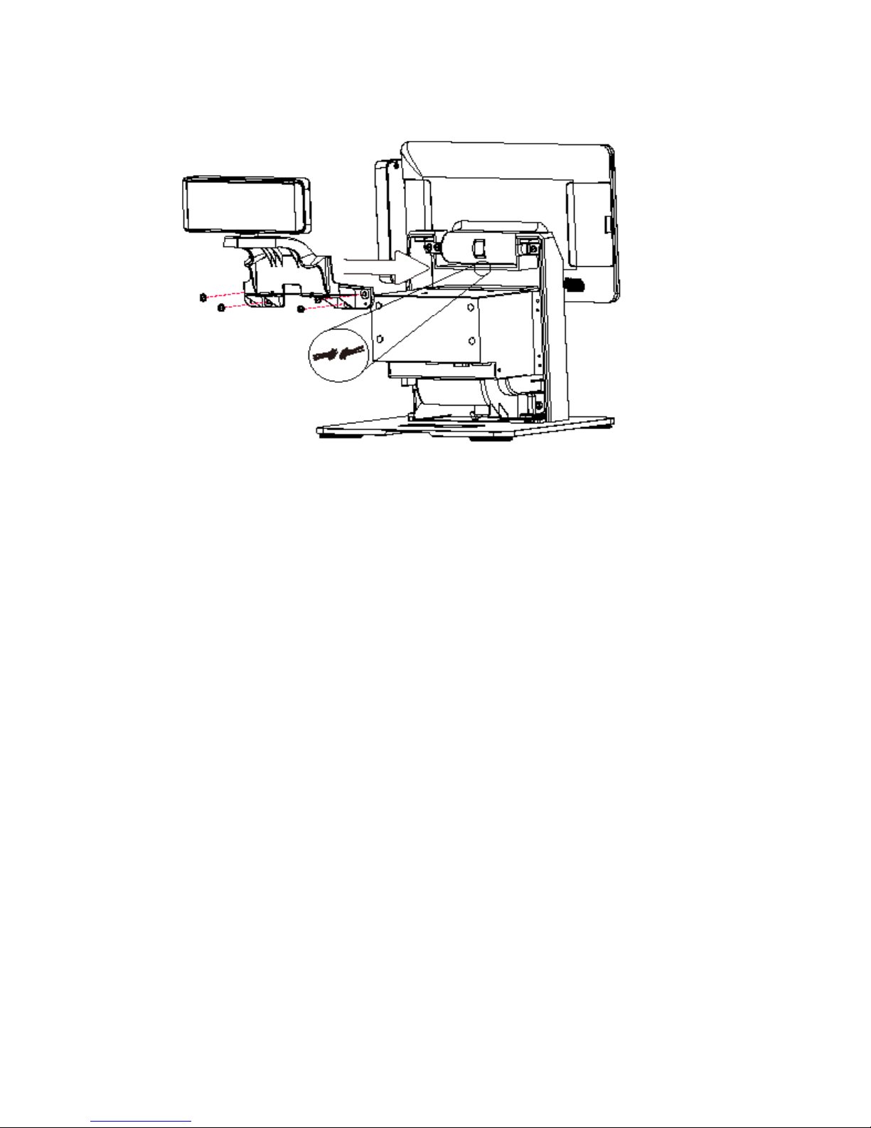
Installing the LCM Module
1. Follow the steps decribed in Chapter 3-1 and 3-2 to open the back cover of the
system, then remove the LCM cover from the back housing.
2. Attach the LCM module and fasten the screws (x4).
3. Connect the LCM cable (x1) to the connector on system side.
4. Close the back cover.
Page 21
12
4-3.
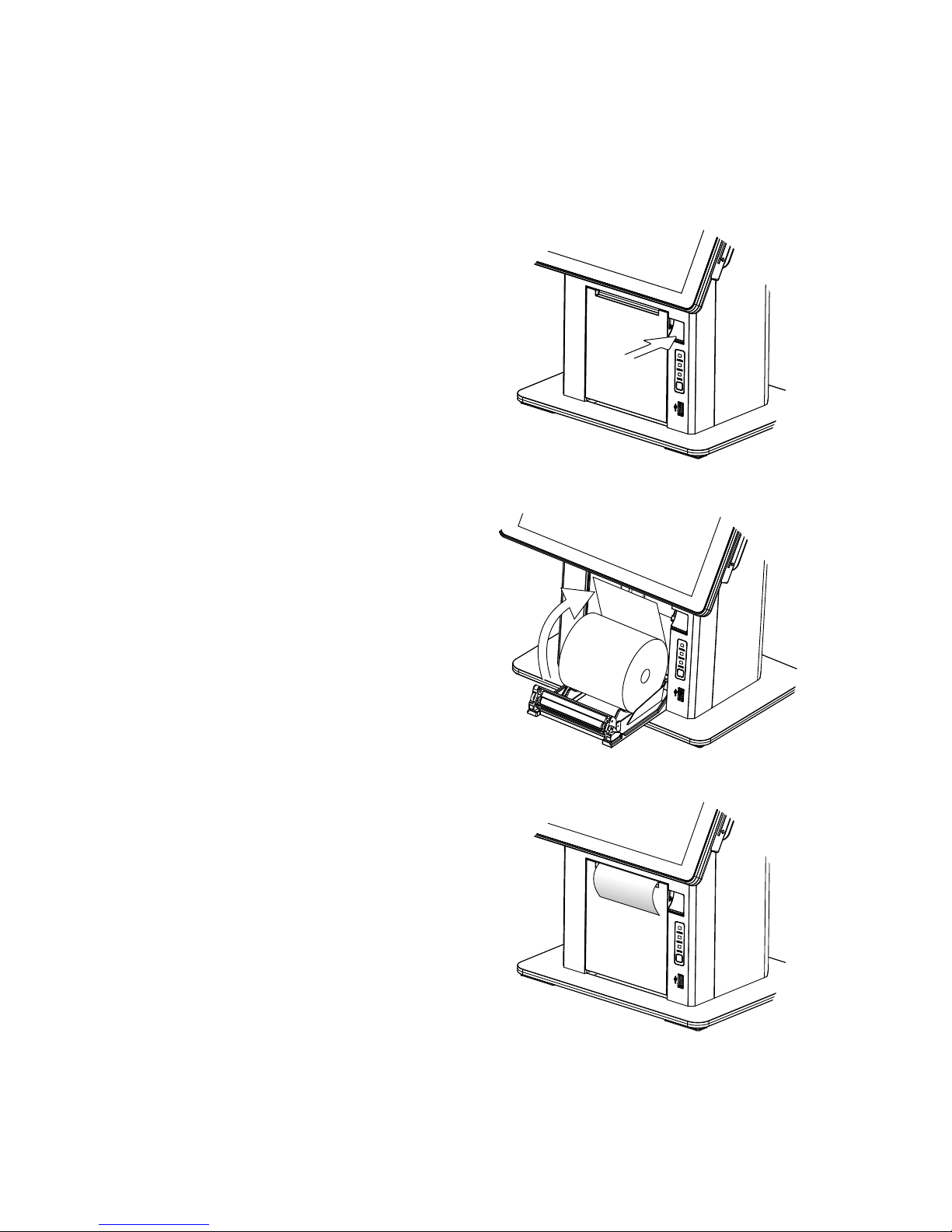
Loading the Thermal Printer Paper
1. Press the button on the right side to
open the thermal printer module.
2. Place the paper roll inside the
printer slot, pull out a length of
paper and then close the cover
over the end of the paper.
3. The paper will automatically feed
through the printer (the system
must be powered on).
Page 22
13
4-4.
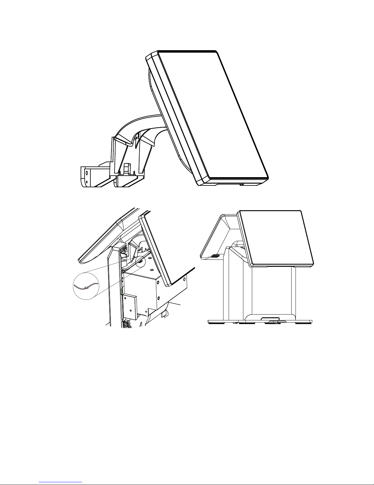
Installing the Rear LCD Module
1. Follow the steps decribed in Chapter 3-1 and 3-2 to open the back cover of the
system, then remove the LCM cover from the back housing.
2. Attach the rear LCD display module and fasten the screws (x4).
3. Connect the rear LCD display cable to the connector on system side.
4. Close the back cover and lock the bolt screw at the bottom of the stand plate.
Page 23
14
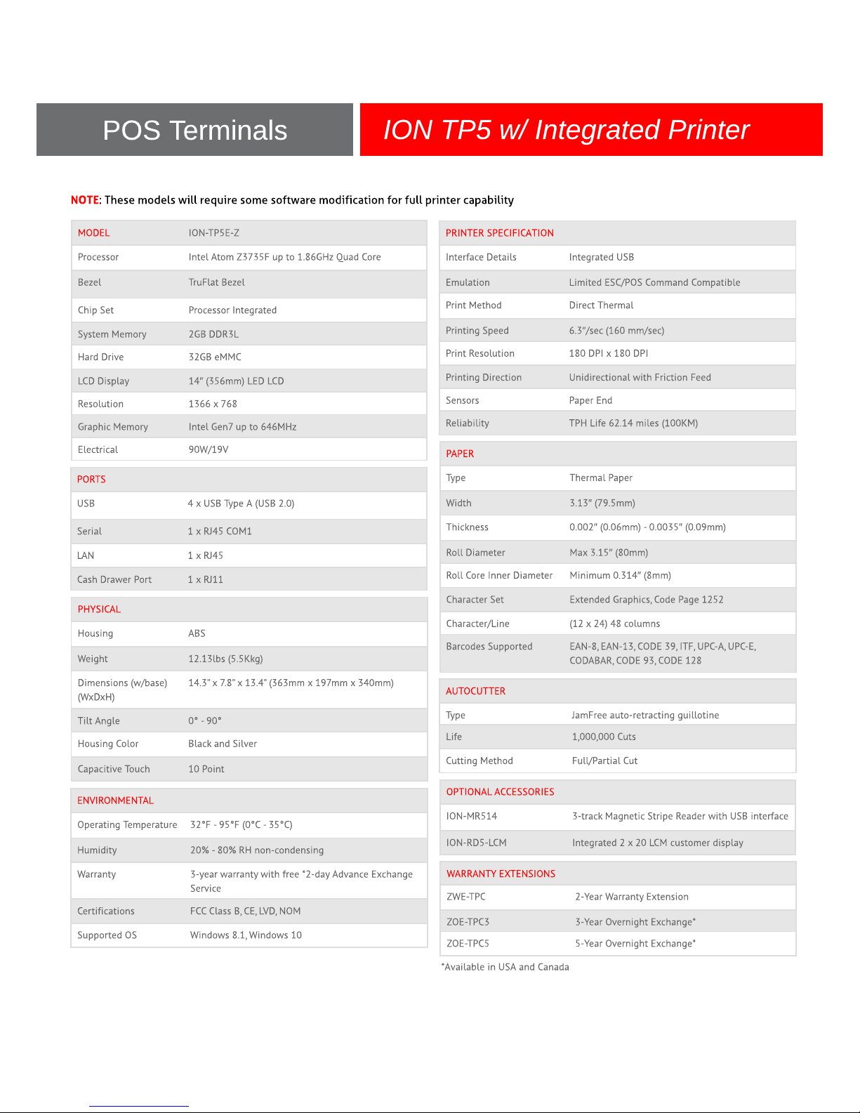
5. Specications
Page 24
15
Page 25
16
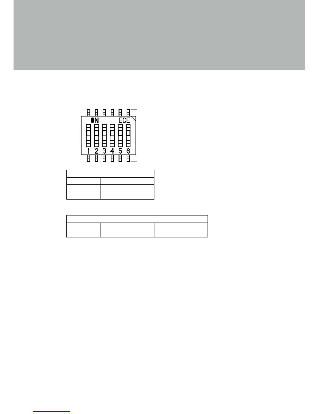
6. Jumper Settings
6-1.
Printer Board Settings
Printer Board
Hardware Reset
Function JP2
Normal * N/C
Reset 1-2
Interface Select
SW1 ON OFF
1 USB COM
ON=Down
OFF=Up
Page 26

17
Appendix: Driver Installation
The shipping package includes a Driver CD, where all drivers and utilities can be found.
Please insert the Driver CD into a computer with a CD drive and open the
“index.htm” le and select the terminal model. For more information please visit
www.pos-x.com
 Loading...