

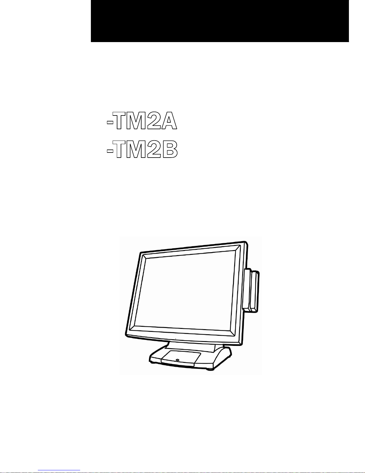
POS-X ION-TM2A, ION-TM2B User Manual
Version 1.1 February 2013
User Manual
-TM2A
-
TM2B
ION
ION
Touchscreen Monitors

i
Copyright 2012
All Rights Reserved
Manual Version 1.4
The information contained in this document is subject to change
without notice.
We make no warranty of any kind with regard to this material,
including, but not limited to, the implied warranties of merchantability
and fitness for a particular purpose. We shall not be liable for errors
contained herein or for incidental or consequential damages in
connection with the furnishing, performance, or use of this material.
This document contains proprietary information that is protected by
copyright. All rights are reserved. No part of this document may be
photocopied, reproduced or translated to another language without
the prior written consent of the manufacturer.
TRADEMARK
Trademarks mentioned herein are the property of their respective
owners.

ii
Safety
IMPORTANT SAFETY INSTRUCTIONS
1. To disconnect the machine from the electrical Power Supply, turn
off the power switch and remove the power cord plug from the wall
socket. The wall socket must be easily accessible and in close
proximity to the machine.
2. Read these instructions carefully. Save these instructions for future
reference.
3. Follow all warnings and instructions marked on the product.
4. Do not use this product near water.
5. Do not place this product on an unstable cart, stand, or table. The
product may fall, causing serious damage to the product.
6. Slots and openings in the cabinet and the back or bottom are
provided for ventilation; to ensure reliable operation of the product
and to protect it from overheating. These openings must not be
blocked or covered. The openings should never be blocked by
placing the product on a bed, sofa, rug, or other similar surface.
This product should never be placed near or over a radiator or heat
register, or in a built-in installation unless proper ventilation is
provided.
7. This product should be operated from the type of power indicated
on the marking label. If you are not sure of the type of power
available, consult your dealer or local power company.
8. Do not allow anything to rest on the power cord. Do not locate this
product where persons will walk on the cord.
9. Never push objects of any kind into this product through cabinet
slots as they may touch dangerous voltage points or short out parts
that could result in a fire or electric shock. Never spill liquid of any
kind on the product.
CE MARK
This device complies with the requirements of the EEC directive
2004/108/EC with regard to “Electromagnetic compatibility” and
2006/95/EC “Low Voltage Directive”
FCC
This device complies with part 15 of the FCC rules. Operation is subject
to the following two conditions:
(1) This device may not cause harmful interference.
(2) This device must accept any interference received, including
interference that may cause undesired operation
iii
Safety Caution
Note: To comply with IEC60950-1 Clause 2.5 (limited power sources,
L.P.S) related legislation, peripherals shall be 4.7.3.2 "Materials for fire
enclosure" compliant.
4.7.3.2 Materials for fire enclosures
For MOVABLE EQUIPMENT having a total mass not exceeding
18kg.the material of a FIRE ENCLOSURE, in the thinnest significant
wall thickness used, shall be of V-1 CLASS MATERIAL or shall pass
the test of Clause A.2.
For MOVABLE EQUIPMENT having a total mass exceeding 18kg
and for all STATIONARY EQUIPMENT, the material of a FIRE
ENCLOSURE, in the thinnest significant wall thickness used, shall
be of 5VB CLASS MATERIAL or shall pass the test of Clause A.1
LEGISLATION AND WEEE SYMBOL
2012/19/EU Waste Electrical and Electronic Equipment Directive on the
treatment, collection, recycling and disposal of electric and electronic
devices and their components.
The crossed dustbin symbol on the device means that it should not be
disposed of with other household wastes at the end of its working life.
Instead, the device should be taken to the waste collection centers for
activation of the treatment, collection, recycling and disposal
procedure.
To prevent possible harm to the environment or human health from
uncontrolled waste disposal, please separate this from other types of
wastes and recycle it responsibly to promote the sustainable reuse of
material resources.

iv
Household users should contact either the retailer where they
purchased this product, or their local government office, for details of
where and how they can take this item for environmentally safe
recycling.
Business users should contact their supplier and check the terms and
conditions of the purchase contract.
This product should not be mixed with other commercial wastes for
disposal.

v
Revision History
Revision Date Description
V1.4 October, 2012 B19 MB added

vi
Table Contents
1 Package Checklist.........................................1
1-1 Standard Items............................................................................... 1
1-2 Optional Items ................................................................................ 2
2 System View...................................................3
2-1 Front View ....................................................................................... 3
2-2 Rear View........................................................................................ 4
2-3 Bottom View.................................................................................... 5
2-4 I/O View........................................................................................... 6
3 Peripheral Installation...................................7
3-1 MSR................................................................................................. 7
3-2 VFD.................................................................................................. 8
3-3 Wall Mount Kit..............................................................................10
4 System Assembly & Disassembly.............. 11
4-1 Remove the System Stand ..........................................................11
5 Specification ............................................... 12
6 Jumper Settings.......................................... 13
6-1 B19 AD board Layout ...................................................................13
6-2 Connectors and Functions...........................................................14
6-3 Jumper Setting .............................................................................15
7 Driver Installation ....................................... 16
 Loading...