

Page 1
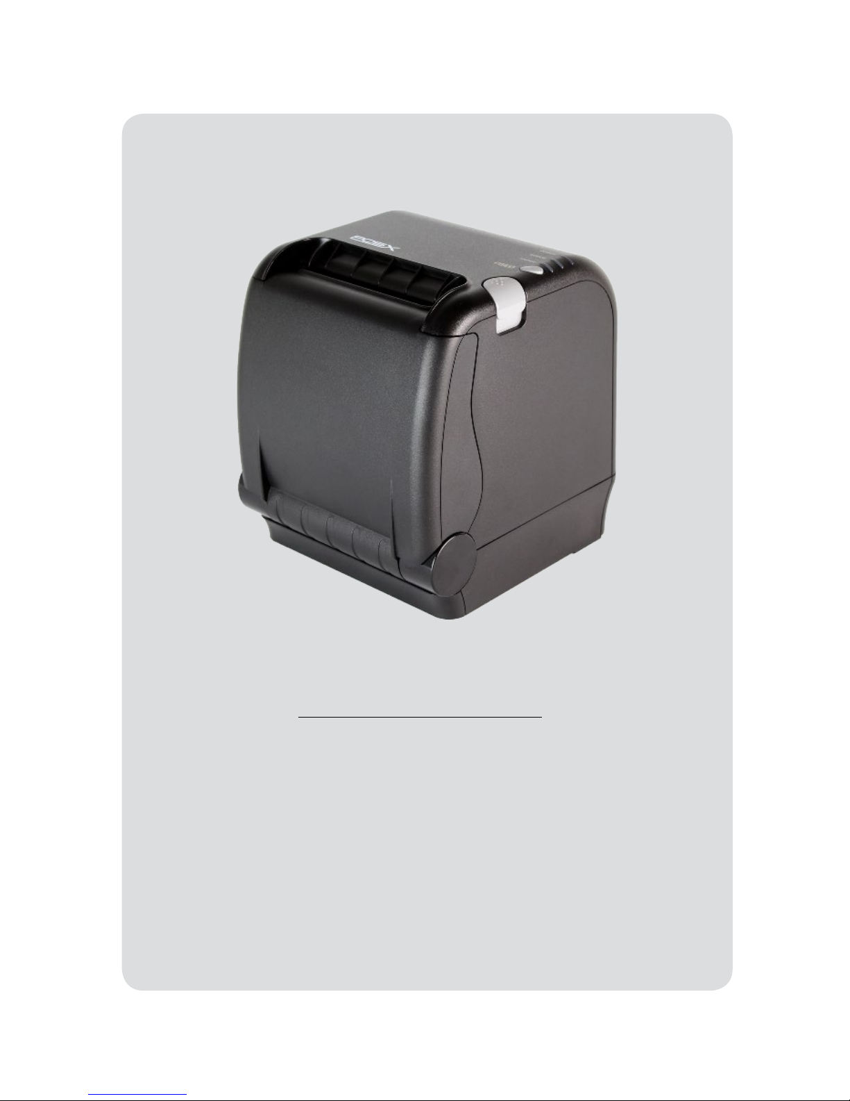
Receipt Printer User’s Manual
MODEL : ION-PT2
All specifications are subject to change without notice
Page 2
2
Table of Contents
1. Parts Identications 3
2. Setting up the printer 4
2.1 Unpacking 4
2.2 Connecting the cables 5
2.3 Loading the paper roll 8
3. Control panel and other functions 10
3.1 Control panel 10
3.2 Error Indicators 10
4. Self Test 11
5. ASCII Print 12
6. Select Baudrate Mode 12
7. Hexadecimal Dump 13
8. Select Error Beep Mode 14
9. Printer Cleaning 14
10. Specications 15
10.1. General Specications 15
10.2. Auto Cutter Specications 16
10.3. Interface 16
10.4. Electrical Characteristics 16
10.5. Environmental Requirements 17
10.6. Reliability 17
10.7. Certication 17
11. Command List 18
Page 3
3
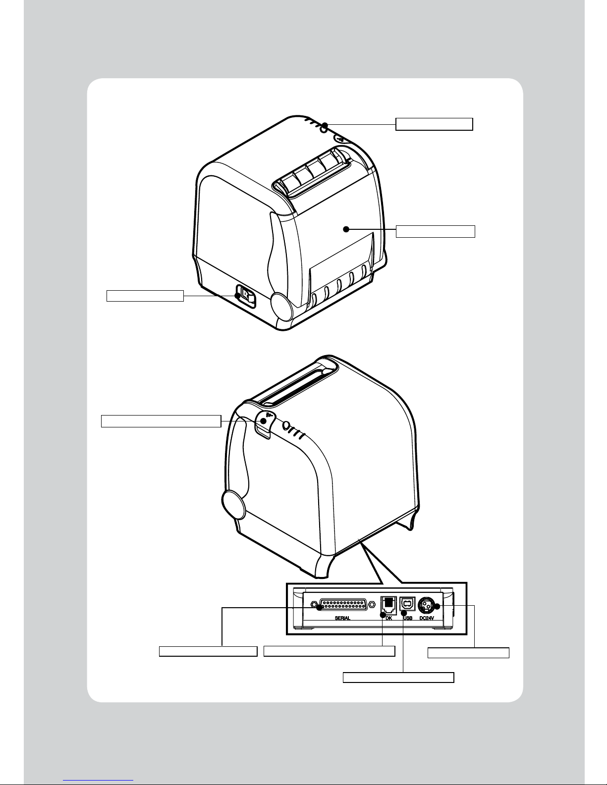
1. Parts Identifications
POWER SWITCH
CONTROL PANEL
PAPER DOOR OPEN BUTTON
INTERFACE CONNECTOR
CASH DRAWER CABLE CONNECTOR
POWER CONNECTOR
INTERFACE CONNECTOR (USB)
Used to turn on/off
power to the printer.
Features LED indicators
to indicate printer status
and buttons to operate
the printer.
Push down this button to
open the paper door.
PRINTER COVER
Open this cover to load or
replace a paper roll.
Page 4
4
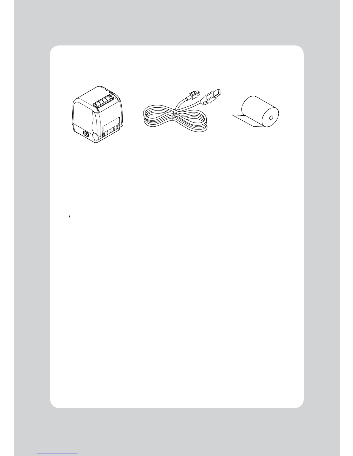
2-1. Unpacking
Your printer box should include these items. If any items are damaged or missing, please contact your
dealer for assistance.
The Printer Interface Cables Paper Roll
2. Setting Up the Printer
Page 5
5
2-2. Connecting the Cables
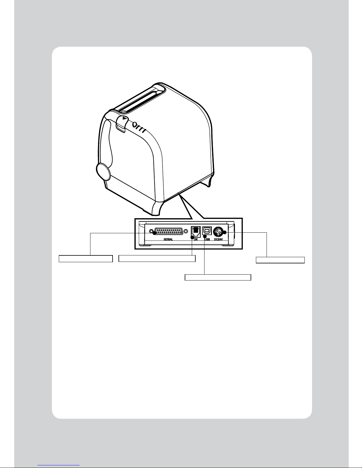
All cables connect to the connector panel on the back of the printer which is shown below:
WARNING: Before connecting any of the cables, make sure both the printer and the computer are
turned off.
For connection to a
host computer.
For connection to a
host computer.
For connection of the
AC adapter.
Never unplug the AC
adapter while the
printer is on.
Connects to peripheral
units such as cash
drawers. Do not
connect this to a
telephone.
INTERFACE CONNECTOR
CASH DRAWER CABLE CONNECTOR
POWER CONNECTOR
INTERFACE CONNECTOR (USB)
Page 6
6
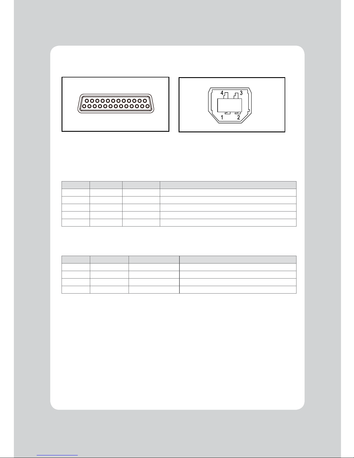
2-2-1. Interface Connector
<D-SUB 25 Female Serial> <USB “B” Type>
25Pin Serial Interface
Pin Signal I/O Description
2 TxD Output Printer transmit data line RS-232C level
3 RxD Input Printer receive data line RS-232C level
4, 20 DTR Output Printer handshake to host line RS-232C level
6 DSR Input Data Send Ready
1,7 GND - System Ground
USB Interface
Pin Signal I/O Description
1 +5V - +5V
2 DATA- - Printer transmit data line
3 DATA+ - Printer transmit data line
4 GND - System Ground
14 25
1 13
Page 7
7
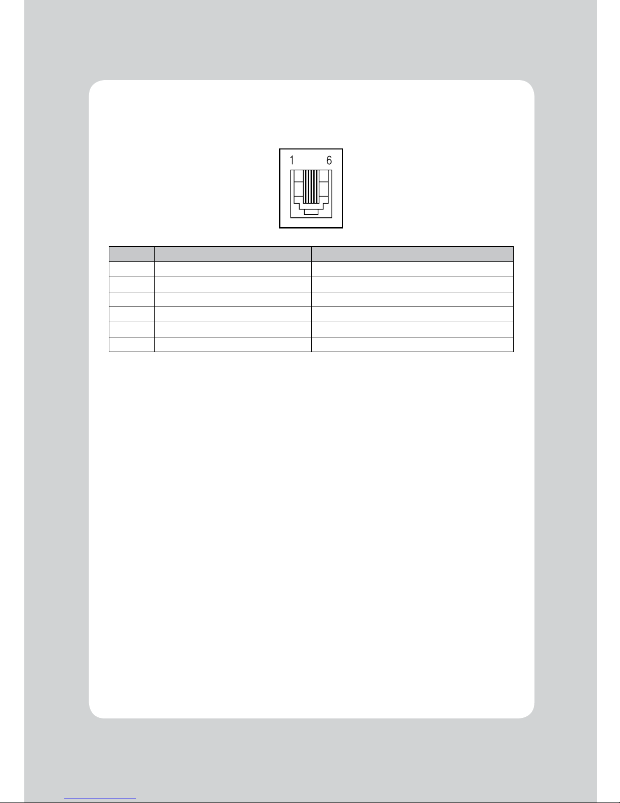
2-2-2. Cash Drawer Connector
The printer can operate two cash drawers with a 6 pin RJ-11 modular connector.
The driver is capable of supplying a maximum current of 1.0A for 510ms or less when not printing.
PIN SIGNAL DESCRIPTION
1 Signal GND 2 Drawer kick-out drive signal 1 Output
3 Drawer open/close signal Input
4 +24V 5 Drawer kick-out drive signal 2 Output
6 Signal GND -
Page 8
8
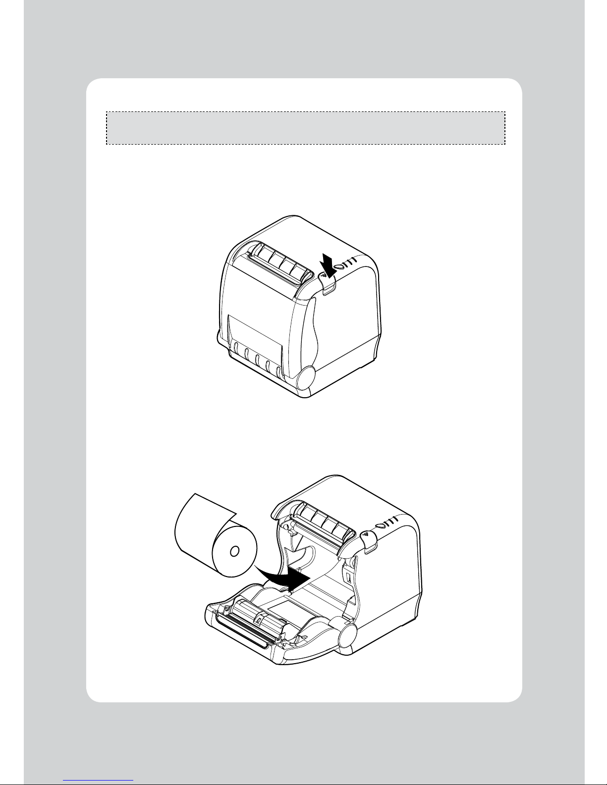
2-3. Loading the Paper Roll
Note: Be sure to use paper rolls that meet the specifications. Do not use paper rolls that have the
paper glued to the core because the printer cannot detect the paper end correctly.
Turn off power switch.
1. Make sure that the printer is not receiving data; Otherwise, data may be lost.
2. Open the printer cover by pushing down the paper door open button.
3. Remove the used paper roll core if there is one inside.
4. Insert new paper roll as shown.
Page 9
9
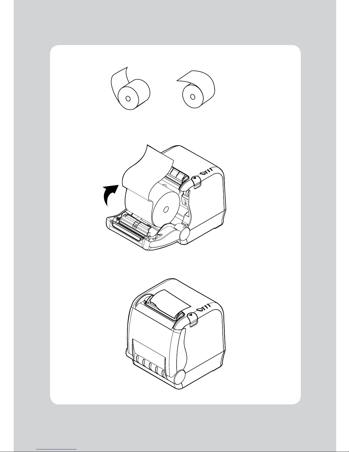
5. Note the correct direction that the paper comes off the roll:
6. Pull out a small amount of paper roll as shown. Then, close the cover.
7. Tear off the paper as shown.
O X
Page 10
10
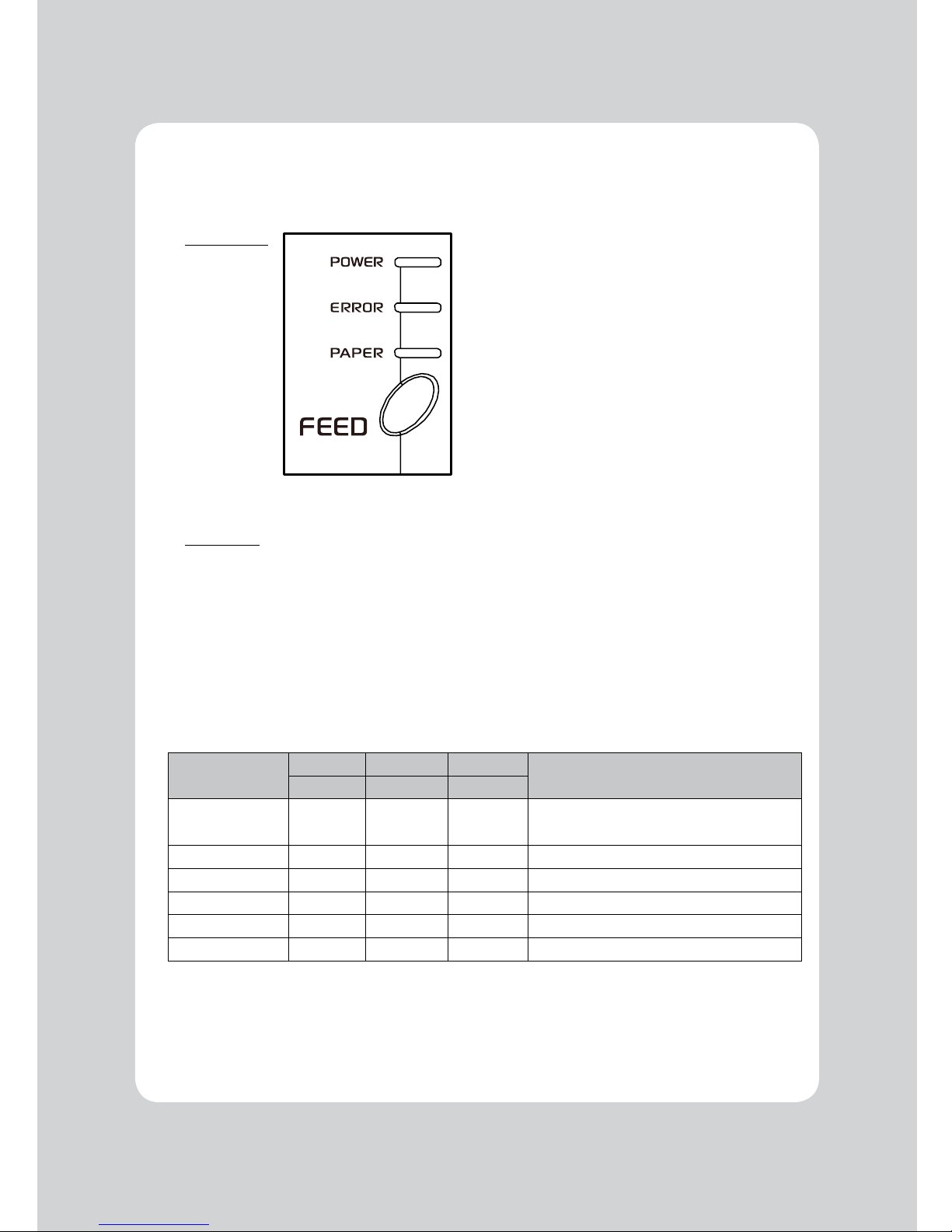
3-1. Control panel
You can control the basic paper feeding operations of the printer with the FEED button on the control
panel. The indicator lights let you to monitor the printer’s status.
Control Panel
Feed Button
The feed button can be disabled using the ESC c 5 command.
Press the FEED button once to advance paper one line. You can also hold down the FEED button to
feed paper continuously.
3-2. Error indicators
This section explains the different patterns signaled by the two LED indicators located on the top cover
of the printer.
STATUS
PAPER ERROR POWER
REMARKS
RED RED GREEN
Power off OFF OFF OFF
Normal power is not supplied to the
printer
Power on OFF OFF ON Normal power is supplied to the printer
Online OFF OFF ON Normal error-free mode
Cover open OFF ON ON Close cover
Paper empty ON ON ON Insert new paper roll
Test mode OFF OFF ON Ignored error led
3. Control panel and other functions
Page 11
11
The self-test result indicates whether the printer is operating properly. With this information the user
can check the following options or status of the printer.
Controlcircuit
Printermechanism
Printingquality
ROMversion
Interfacesetting
Thistestisindependentofanyotherequipmentorsoftware.
Running the self test
1. Make sure the printer is turned off and the printer cover is closed properly before performing the self test
2. Turn the printer on while holding the FEED button until the self-test starts printing. The self-test prints the
printer
settings then prints the following, and pauses. (Error LED On)
SELECT MODE BY BUTTON
1. ASCII PRINT
2. SELECT BAUDRATE MODE
3. HEXADUMP MODE
4. SELECT ERROR BEEP MODE
3. Press the FEED button consecutively (1~4)
1. ASCII PRINT
(press the FEED button once)
Printing test page constructed with ACII code.
2. SELECT BAUDRATE MODE
(press the FEED button twice)
Set the speed of Serial Interface
(You can set the BAUDRATE in this mode)
3. HEXADUMP MODE
(press the FEED button triple time)
Printing the HEX value received from the interface
4. SELECT ERROR BEEP MODE Select Printer Error Beep On/Off
Wait for 5~6 seconds if you want to exit. Printer performs a cut when exiting this mode
4. The printer is ready to receive data after finishing the self test.
4. Self Test
Page 12

12
ASCII PRINT prints a test page with ASCII codes. You can use this function to check printer functionality.
The ASCII PRINT test automatically ends and cuts the paper after printing the following:
*** Completed ***
The printer is ready to receive data as soon as it completes the ASCII PRINT.
5. ASCII Print
After entering the BAUDRATE MODE, the list of baudrates that can be selected will be printed.
Similar to the Self Test, you can press the FEED button to select a BAUDRATE. Once the feed button
is pressed to select the baudrate, the printer shows the selected baudrate and stores the setting. The
printer is ready to receive data as soon as it completes the function.
SELECT BAUDRATE BY BUTTON
1. 9600bps
2. 19200bps
3. 38400bps
4. 115200bps
6. Select Baudrate Mode
Page 13

13
8. Select Error Beep Mode
7. Hexadecimal Dump
This feature allows experienced users to see exactly what data is sent to the printer. This can be
useful in finding software problems.
When you go into the hex dump function, the printer prints all commands and other data in
hexadecimal format along with a guide section to help you find specific commands.
To use the hex dump feature, follow these steps
1. Turn printer off.
2. Turn printer on while press down the “Feed” button.
3. Press the FEED button three times when the Self Test is printed.
4. Now the printer is in Hex dump mode.
5. Run any software program that sends data to the printer. The printer prints ”Hexadecimal printing
mode…” and then all the codes it receives in a two-column format. The first column contains the
hecadecimal codes and the second column gives the ASCII characters that correspond to the codes.
Hecadecimal Dump
1B 21 00 1B 26 02 40 40 .!..& . @ @
1B 25 01 1B 63 34 00 1B .%..c4 ..
41 42 43 44 45 46 47 48 ABCDEFGH
□Aperiod(.)isprintedforeachcodethathasnoASCIIequivalent.
6. Turn off the printer.
7. Turn on the printer.
This function sets the ON/OFF status of the beep mode when the printer has an error such as low
paper, open paper door, etc.
When this mode is selected, the printer will print text similiar to the text shown below. Press the
FEED button once or twice to select the ON/OFF mode.
SELECT ERROR BEEP MODE BY BUTTON
1. BEEP MODE ON
2. BEEP MODE OFF
Page 14
14
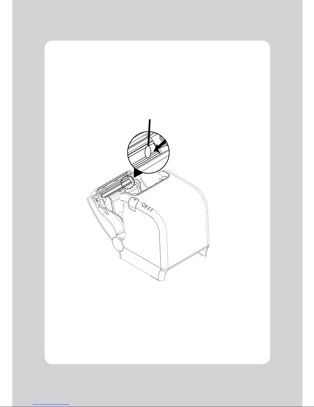
9. Printer cleaning
Iftheinterioroftheprinterisdusty,theprintingqualitycanbereduced.
In this case, follow the instructions below to clean the printer.
1. Use an applicator swab moistened with an alcohol solution to clean the print head and remove
any dusts.
2. Once the cleaning is completed, wait a few minutes before adding paper and closing the paper
door.
Note:
1. Make sure to turn the printer power off prior to cleaning.
2. Wait 10 minutes for the print head to cool before cleaning it as it can get very hot during during use.
3. When cleaning the print head, take care not to touch the heated part of the print head.
The print head may be damaged by static electricity.
4. Take care not to allow the print head to become scratched and /or damaged in any way.
Page 15
15
IMPORTANT!
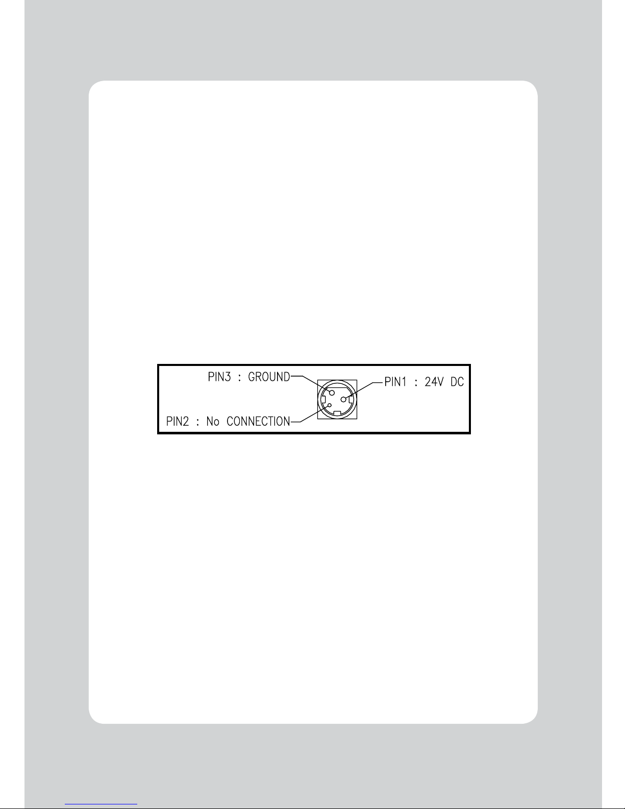
When connecting or disconnecting the power supply from the printer, be sure that the following
cautions are observed.
Use a power supply (Limited Power Supply) of DC 24V±10% and more than 1.75A.
Try to avoid installing the printer in an area where there is electrical noise.
Take the appropriate measures to protect against electrostatic AC line noise, etc.
10-1. General Specications
(1) Printing Method Direct line thermal printing.
(2) Print speed 220mm/sec
(3) Dot density (Hor / Ver) 180 DPI X 180 DPI
(4) Dot Pitch 0.141mm X 0.141mm
(5) Printing Width Max 72mm (512 dots/Line)
(6) Number of print columns.
Font “A” Font “B”
42 columns 56 columns
(7) Roll paper Refer to chapter 2 for details on the recommended paper rolls.
Paper width : Default 79.5 ±0.5mm
Roll diameter : Max. ø83mm
(8) Weight 1.7 Kg
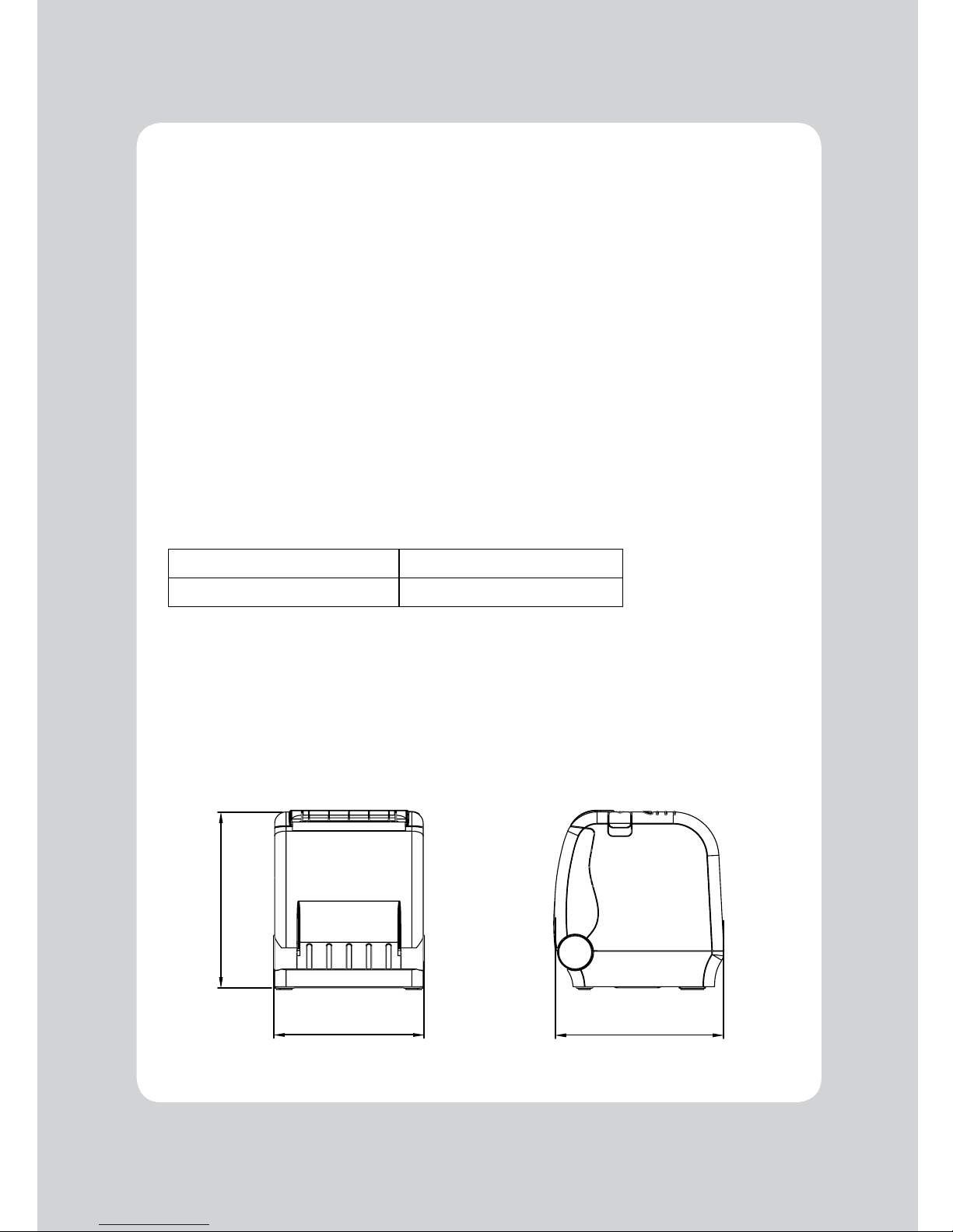
(8) Overall dimension
10. Specifications
132,00
154,50
147,72
Page 16
16
10-2. Auto Cutter Specications
(1)CuttingFrequency Max.30cutsperminute
(2) Thickness of paper 0.06 ~ 0.08 mm
(3) Cutter Life 1.5 million cuts
(if the paper thickness is between 65 and 80µm)
10-3. Interface
USB (B type) + Serial or Ethernet built-in
10-4. Electrical Characteristics
(1) Input Voltage DC 24V ± 10%
(2) Current Consumption Operating: Approx. 1.5 A (at ASC∥ printing)
Peak : Approx. 10 A
(at print duty 100%, For 10 seconds or less)
Stand-by : Approx. 0.03 A
(3) Power Connector
Page 17

17
10-5. Environmental Requirements
(1) Operating
Temperature 5°F to 104°F (5°C to 40°C)
Humidity 10% to 90% RH (without condensation)
(2) Transport/Storage (no paper)
Temperature -20°F to 140°F (-20°C to 60°C)
Humidity 10% to 90% RH (without condensation)
10-6. Reliability
(1) MCBF 70 million lines
(2) Print Head Life 100 million pulses, 150Km
(3) Cutter Life 1.5 million cuts (if the paper thickness is between 65 and 80µm)
10-7. Certication
(1) FCC PART15 CLASS A
(2) UL/cUL (UL 60950-1)
(3) KC
(4) CE-EMCD Class B
(5) ENERGY STAR
Thisequipmentisintededforindooruse.Anydamagecausedbyusingthisdeviceoutdoorsisnot
covered under warranty.
Page 18
18
No. Command Function REMARKS
1 HT Horizontal tab
2 LF Print and line feed
3 CR Print and carriage return
4 FF Print and return to standard mode (in page mode)
5 CAN Cancel print data in page mode
6 DLE EOT Real-time status transmission
7 DLE ENQ Real-timerequesttoprinter
8 DLE DC4 Generate pulse at real-time
9 ESC FF Print data in page mode
10 ESC SP Set right-side character spacing
11 ESC ! Select print mode(s)
12 ESC $ Set absolute print position
13 ESC % Select/cancel user-defined character set
14 ESC & Define user-defined characters
15 ESC * Set bit-image mode
16 ESC - Turn underline mode on/off
17 ESC 2 Select default line spacing
18 ESC 3 Set line spacing
19 ESC = Select peripheral device
20 ESC ? Cancel user-defined characters
21 ESC @ Initialize printer
22 ESC D Set horizontal tab positions
23 ESC E Turn emphasized mode on/off
24 ESC G Turn double-strike mode on/off
25 ESC J Print and feed paper using minimum units
26 ESC L Select page mode
27 ESC M Select character font
28 ESC R Select an international character set
29 ESC S Select standard mode
30 ESC T Select print direction in page mode
31 ESC V Turn 90° clockwise rotation mode on/off
32 ESC W Set printing area in page mode
33 ESC \ Set relative print position
34 ESC a Select justification
35 ESC c 3 Select paper sensor(s) to output paper-end signals
36 ESC c 4 Select paper sensor(s) to stop printing
37 ESC c 5 Enable/disable panel buttons
38 ESC d Print and feed paper n lines
39 ESC p General pulse
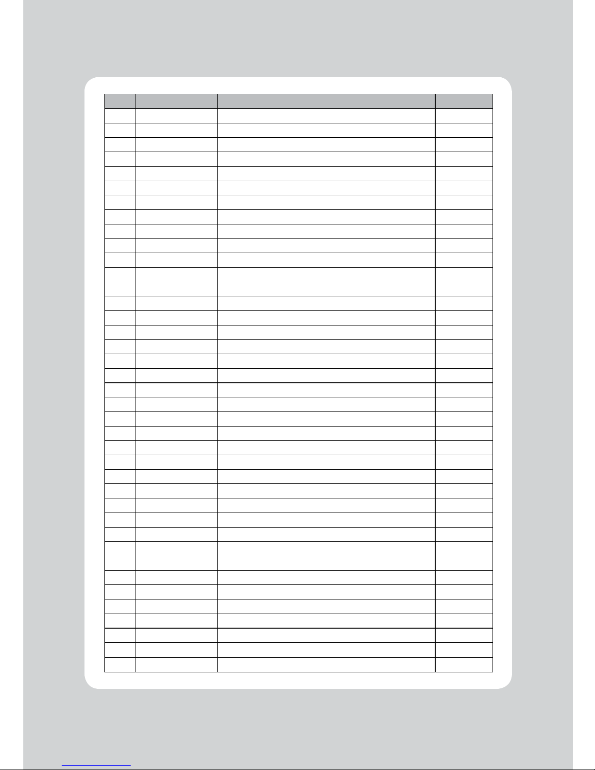
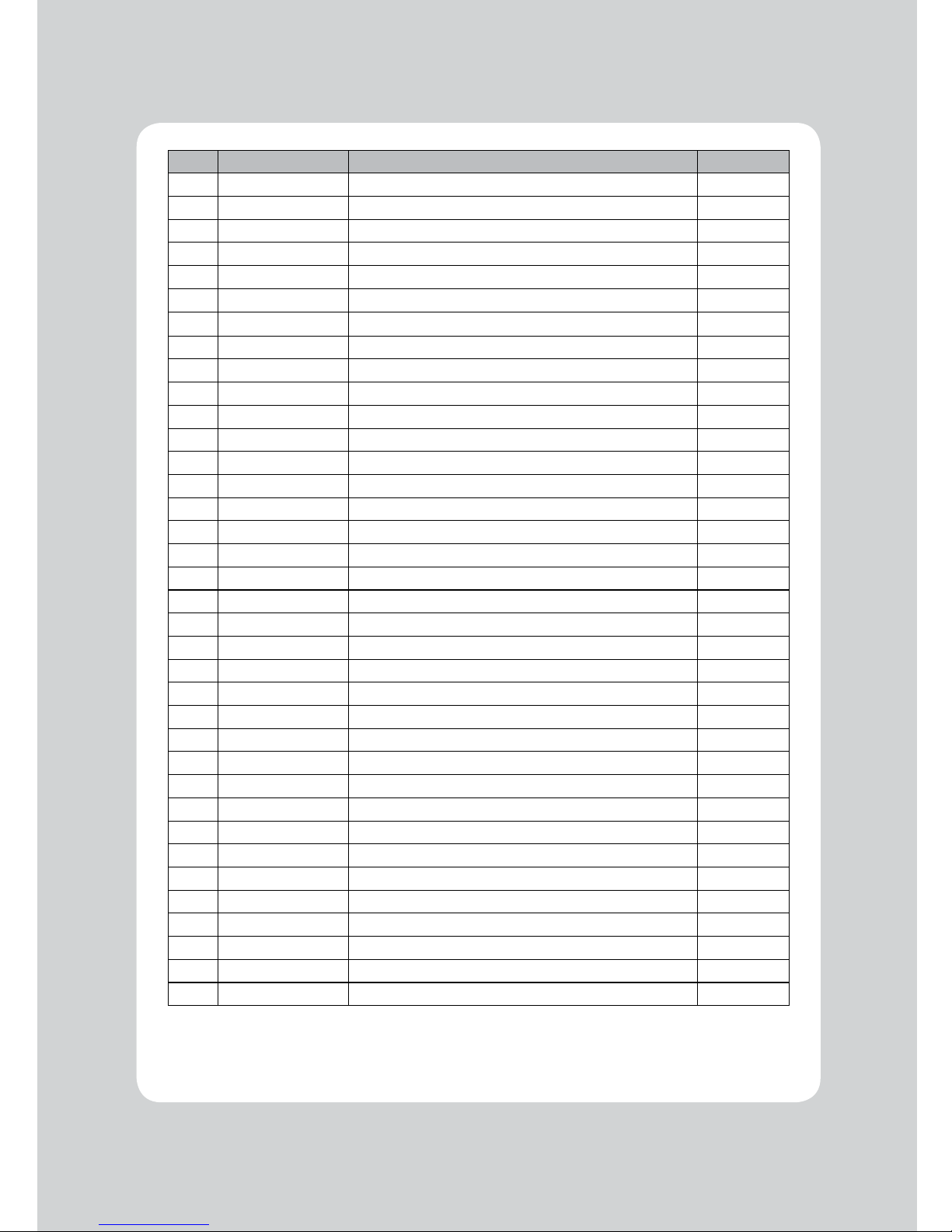
11. Command List
Page 19
19
No. Command Function REMARKS
40 ESC t Select character code table
41 ESC { Turn upside-down printing mode on/off
42 FS p Print NV bit image
43 FSq Define NV bit image
44 GS ! Select character size
45 GS $ Set absolute vertical print position in page mode
46 GS * Define downloaded bit image
47 GS / Print downloaded bit image
48 GS B Turn white/black reverse printing mode on/off
49 GS H Select printing position of HRI characters
50 GS I Transmit printer ID
51 GS L Set left margin
52 GS P Set horizontal and vertical motion units
53 GS V Select cut mode and cut paper
54 GS W Set printing area width
55 GS \ Set relative vertical print position in page mode
56 GS a Enable/disable Automatic Status Back(ASB)
57 GS f Select font for HRI characters
58 GS h Set bar code height
59 GS k Print bar code
60 GS r Transmit status
61 GS v 0 Print raster bit image
62 GS w Set bar code width
< Add >
1 ESC i Full cut
2 ESC m Partial cut
3 FS ! Set print mode(s) for Kanji characters
4 FS & Select Kanji character mode
5 FS - Turn underline mode on/off for Kanji character
6 FS . Cancel Kanji character mode
7
FS 2 c1 d1…dk
Define user-defined Kanji characters
8 FS C Select Kanji character code system
9 FS S 1 2 Set Kanji character spacing
10 FS W Turnquadruple-sizemodeon/offforKanjicharacter
 Loading...