

Page 1
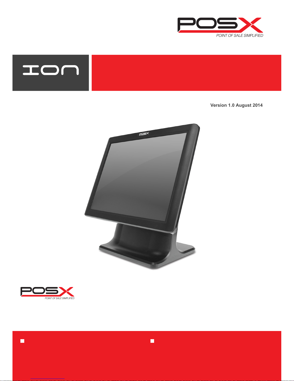
Fit Touchscreen Monitor
User Manual
Version 1.0 August 2014
POS-X Warranty POS-X Service and Support
Industry-leading Warranty Protection
• 3 year warranty
• *2-day Advance Exchange - standard on all products
• Warranty extensions and overnight exchanges are available
to provide means to further reduce the total cost of
ownership
24/7 Technical Support and Lifetime Customer Support
• 24/7 access to our USA-based experienced technical
support representatives
• Support techs utilize advanced techniques such as
remote access for quick and accurate system analysis
• Lifetime support on all POS-X products
*Available in USA and Canada
1975 Midway Lane, Suite O
Bellingham, WA 98226
[email protected]
360.738.8433
www.pos-x.com
Page 2

i
Copyright 2014
All Rights Reserved
Manual Version 1.0
The information contained in this document is subject to change without notice.
We make no warranty of any kind with regard to this material, including, but not
limited to, the implied warranties of merchantability and fitness for a particular
purpose. We shall not be liable for errors contained herein or for incidental or
consequential damages in connection with the furnishing, performance, or use of
this material.
This document contains proprietary information that is protected by copyright. All
rights are reserved. No part of this document may be photocopied, reproduced or
translated to another language without the prior written consent of the
manufacturer.
TRADEMARK
Intel®, Pentium® and MMX are registered trademarks of Intel® Corporation.
Microsoft® and Windows® are registered trademarks of Microsoft Corporation.
Other trademarks mentioned herein are the property of their respective owners.
Page 3
ii
Safety
IMPORTANT SAFETY INSTRUCTIONS
1. To disconnect the machine from the electrical Power Supply, turn off the power
switch and remove the power cord plug from the wall socket. The wall socket
must be easily accessible and in close proximity to the machine.
2. Read these instructions carefully. Save these instructions for future reference.
3. Follow all warnings and instructions marked on the product.
4. Do not use this product near water.
5. Do not place this product on an unstable cart, stand, or table. The product may
fall, causing serious damage to the product.
6. Slots and openings in the cabinet and the back or bottom are provided for
ventilation; to ensure reliable operation of the product and to protect it from
overheating. These openings must not be blocked or covered. The openings
should never be blocked by placing the product on a bed, sofa, rug, or other
similar surface. This product should never be placed near or over a radiator or
heat register, or in a built-in installation unless proper ventilation is provided.
7. This product should be operated from the type of power indicated on the marking
label. If you are not sure of the type of power available, consult your dealer or
local power company.
8. Do not allow anything to rest on the power cord. Do not locate this product where
persons will walk on the cord.
9. Never push objects of any kind into this product through cabinet slots as they
may touch dangerous voltage points or short out parts that could result in a fire
or electric shock. Never spill liquid of any kind on the product.
CE MARK
This device complies with the requirements of the EEC directive 2004/108/EC
with regard to “Electromagnetic compatibility” and 2006/95/EC “Low Voltage
Directive”
FCC
This device complies with part 15 of the FCC rules. Operation is subject to the
following two conditions:
(1) This device may not cause harmful interference.
(2) This device must accept any interference received, including interference that
may cause undesired operation
Page 4
iii
CAUTION ON LITHIUM BATTERIES
There is a danger of explosion if the battery is replaced incorrectly. Replace only with
the same or equivalent type recommended by the manufacturer. Discard used
batteries according to the manufacturer’s instructions.
Battery Caution
Risk of explosion if battery is replaced by an incorrectly type.
Dispose of used battery according to the local disposal instructions.
Safety Caution
Note: To comply with IEC60950-1 Clause 2.5 (limited power sources, L.P.S) related
legislation, peripherals shall be 4.7.3.2 "Materials for fire enclosure" compliant.
4.7.3.2 Materials for fire enclosures
For MOVABLE EQUIPMENT having a total mass not exceeding
18kg.the material of a FIRE ENCLOSURE, in the thinnest significant
wall thickness used, shall be of V-1 CLASS MATERIAL or shall pass
the test of Clause A.2.
For MOVABLE EQUIPMENT having a total mass exceeding 18kg
and for all STATIONARY EQUIPMENT, the material of a FIRE
ENCLOSURE, in the thinnest significant wall thickness used, shall
be of 5VB CLASS MATERIAL or shall pass the test of Clause A.1
LEGISLATION AND WEEE SYMBOL
2012/19/EU Waste Electrical and Electronic Equipment Directive on the treatment,
collection, recycling and disposal of electric and electronic devices and their
components.
The crossed dustbin symbol on the device means that it should not be disposed of
with other household wastes at the end of its working life. Instead, the device
should be taken to the waste collection centers for activation of the treatment,
collection, recycling and disposal procedure.
To prevent possible harm to the environment or human health from uncontrolled
waste disposal, please separate this from other types of wastes and recycle it
responsibly to promote the sustainable reuse of material resources.
Household users should contact either the retailer where they purchased this
product, or their local government office, for details of where and how they can take
this item for environmentally safe recycling.
Business users should contact their supplier and check the terms and conditions of
the purchase contract.
This product should not be mixed with other commercial wastes for disposal.
Page 5

iv
Revision History
Revision Date Description
V1.0 March, 2014 Release
Page 6

v
1 Item Checklist.........................................................1
1-1 Standard Items............................................................................... 1
1-2 Optional Items ................................................................................ 2
2 System View............................................................3
2-1 Front View & Side View ..................................................................3
2-2 Rear View........................................................................................ 4
2-3 Dimension....................................................................................... 4
2-4 I/O View........................................................................................... 5
3 System Assembly & Disassembly..........................6
3-1 Install the Power Adapter............................................................... 6
4 Peripherals Installation..........................................7
4-1 Install the MSR Module .................................................................7
4-2 Install the Fingerprint Module .........................................................8
4-3 Install the Customer Display........................................................ 9
5 Specification........................................................ 10
6 Jumper Settings................................................... 11
6-1 Motherboard Layout.....................................................................11
6-2 Connectors and Functions...........................................................12
6-3 Jumper Settings ...........................................................................13
Appendix: Driver Installation ................................. 15
Table of Contents
Page 7
1
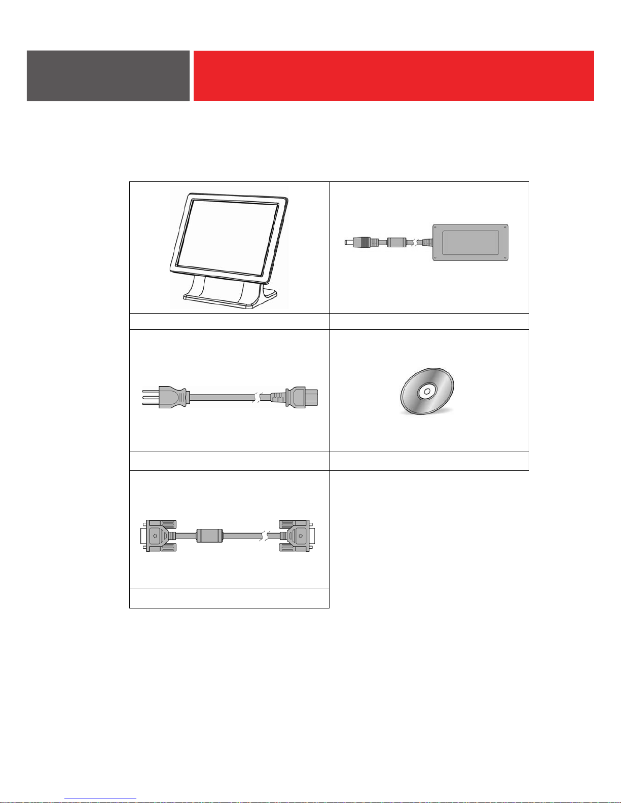
1-1 Standard Items
a. .b metsyS Power adapter (65W)
c. .d elbac rewoP
VGA cable
Driver CD
e.
Item Checklist
1
Page 8
2
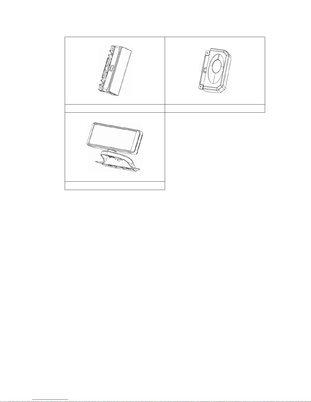
1-2 Optional Items
a. MSR module b. Fingerprint module
c. Customer display
Page 9
3
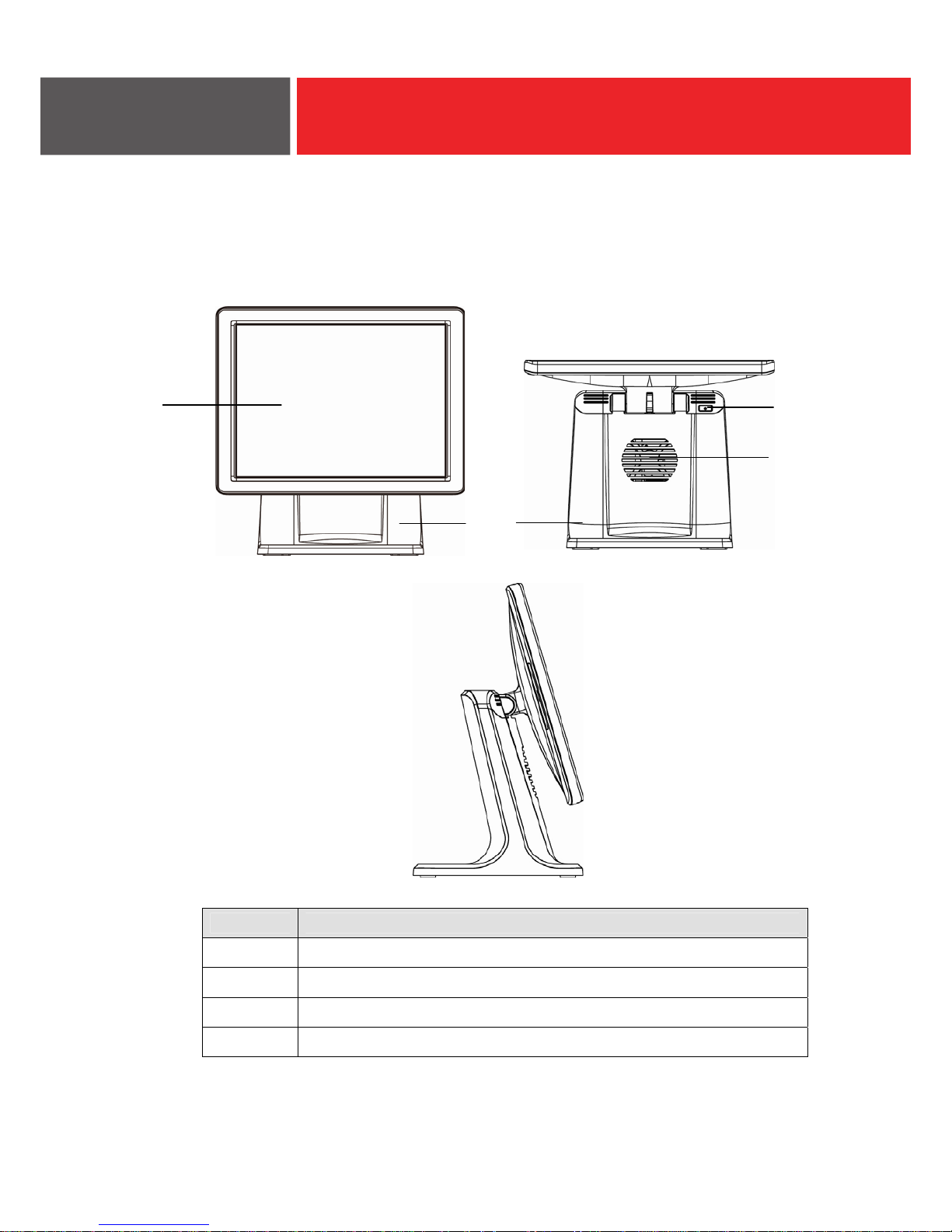
2-1 Front View & Side View
No. Description
neercs hcuoT 1
esab dnatS 2
nottub rewoP 3
eloh noitalitneV 4
1
2
4
3
System View
2
Page 10
4
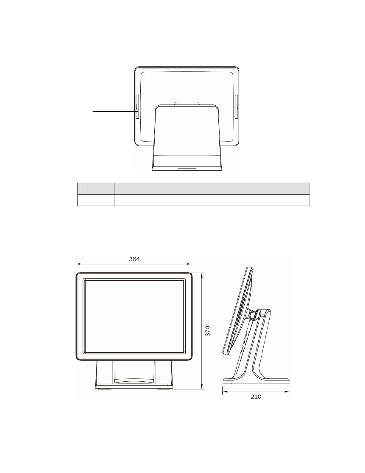
2-2 Rear View
No. Description
5 MSR /Fingerprint / iButton dummy cover
2-3 Dimension
5
5
Page 11
5
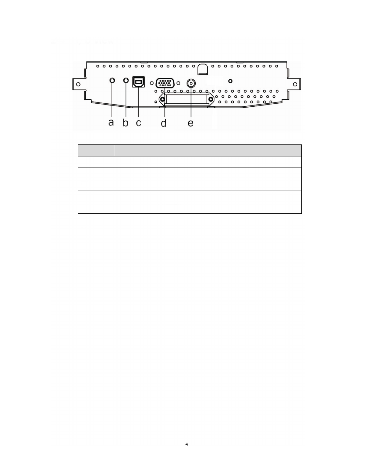
2-4 I/O View
Number Description
tsujda otuA :nottub DSO a
rewoP :nottub DSO b
)CP ot B epyT( 0.2 BSU c
AGV d
kcaJ CD e
Page 12
6
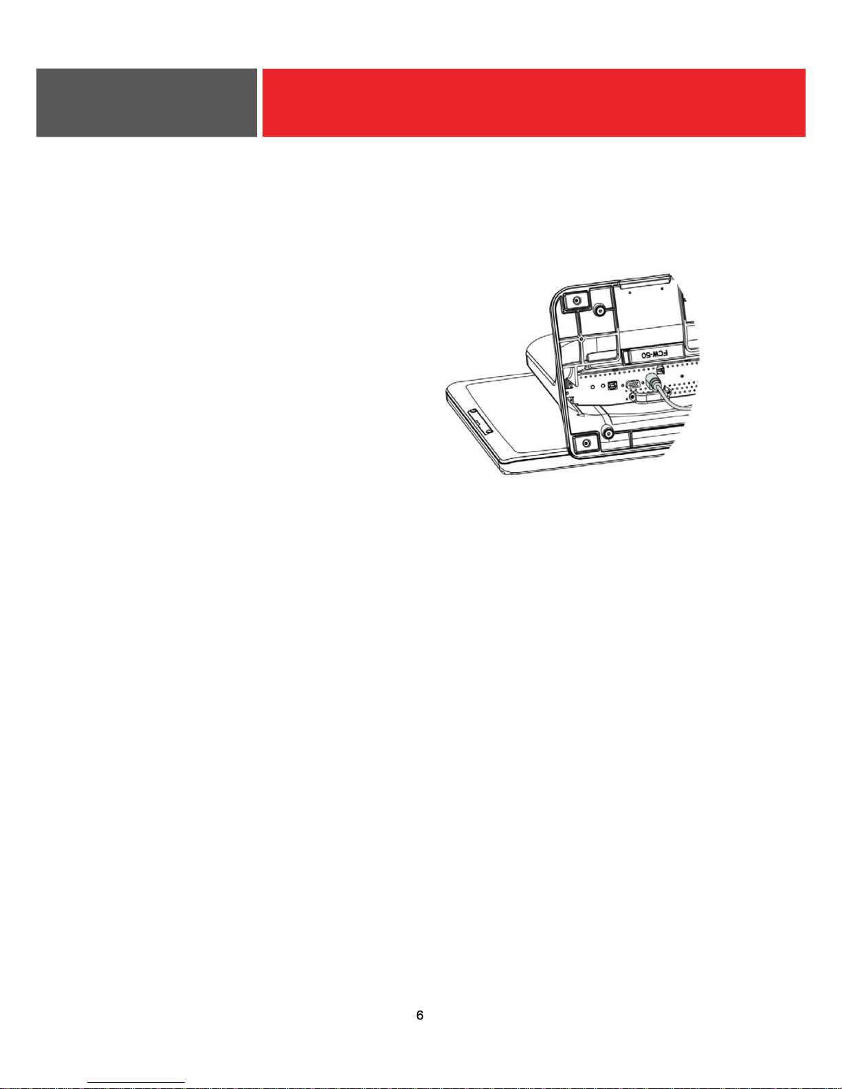
3-1 Install the Power Adapter
The system is equipped with a 36W power adapter. Please plug it into the
system as shown below.
1. Place the system face down.
Make sure not to scratch the
monitor.
2. You will find the I/O panel
located in the bottom of the
stand.
3. Find the DC Jack on the I/O
panel(refer to chapter 2-4.) and
connect the power adapter
directly to the DC jack
connector
System Assembly
3
Page 13
7
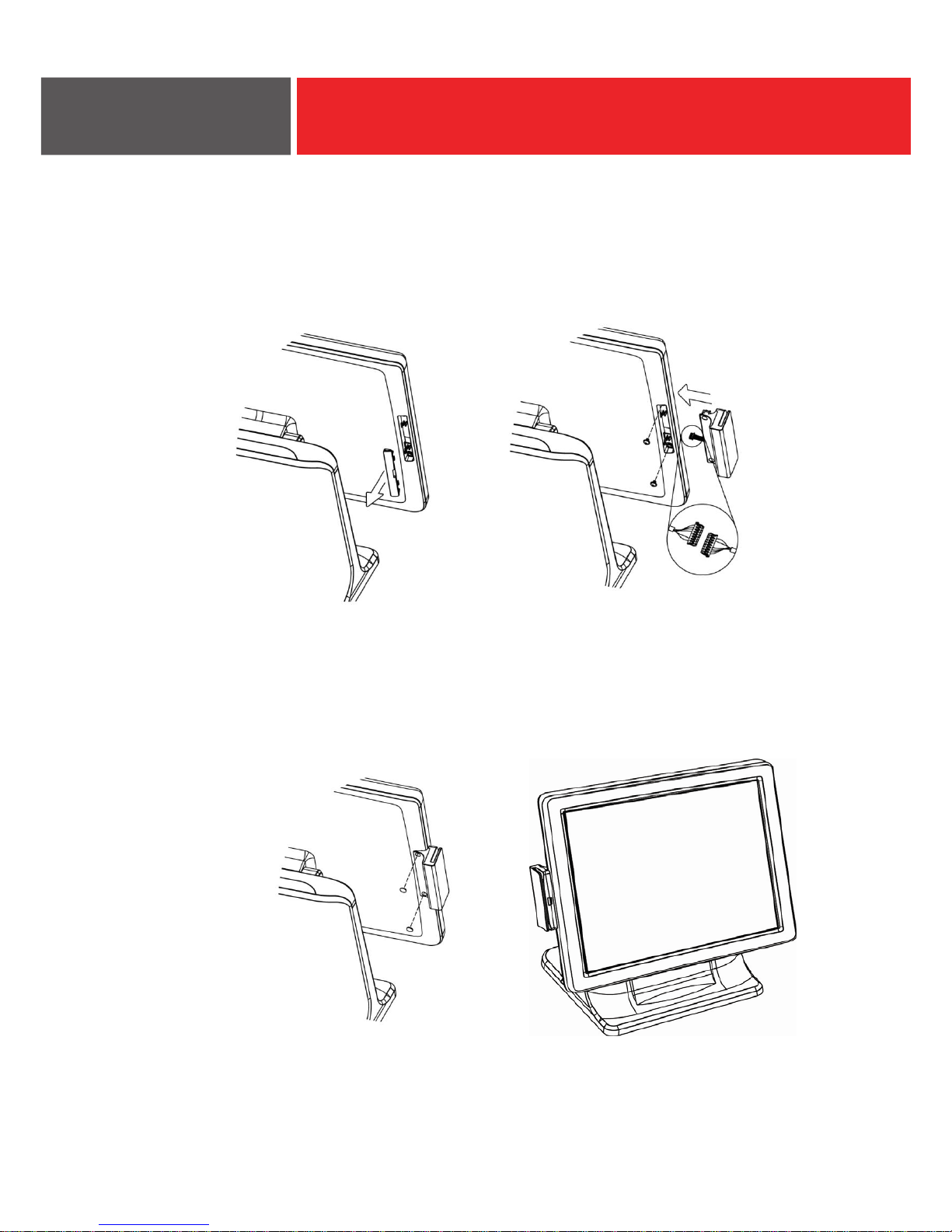
4-1 Install the MSR Module
MSR module can be installed on the right side of the system. Make sure the
unit is powered down before starting.
1. Remove the dummy cover first.
2. Connect the MSR cable to the connector on the system side.
3. Remove both M3*6 screws in the MSR compartment.
4. Insert the MSR module in place and fasten the M3*8L screws (x2) on the
back to secure the module.
5. Finally cover the screw holes by the rubber pads (x2).
Item Checklist
4
Page 14
8
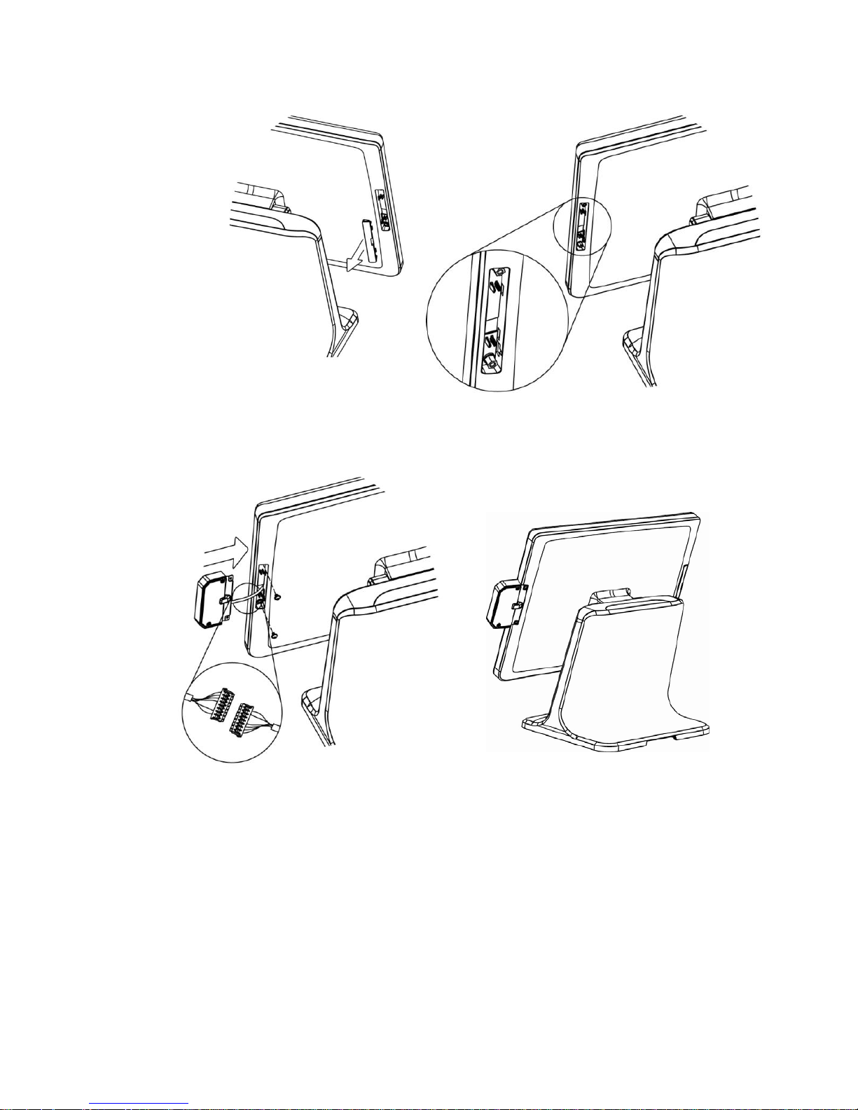
4-2 Install the Fingerprint Module
1. Remove the dummy cover first.
2. Remove the M3*6 screws (x2).
3. Fix the hex standoffs (x2) to the screw hole as shown in the picture.
4. Connect the fingerprint cables to the connector on the system side.
5. Insert the fingerprint module in place and fasten the M3*4 screws (x2) on the
back to secure the module.
*Please note the M3*6 screws (x2) should be removed before inserting the
Fingerprint module.
Page 15
9
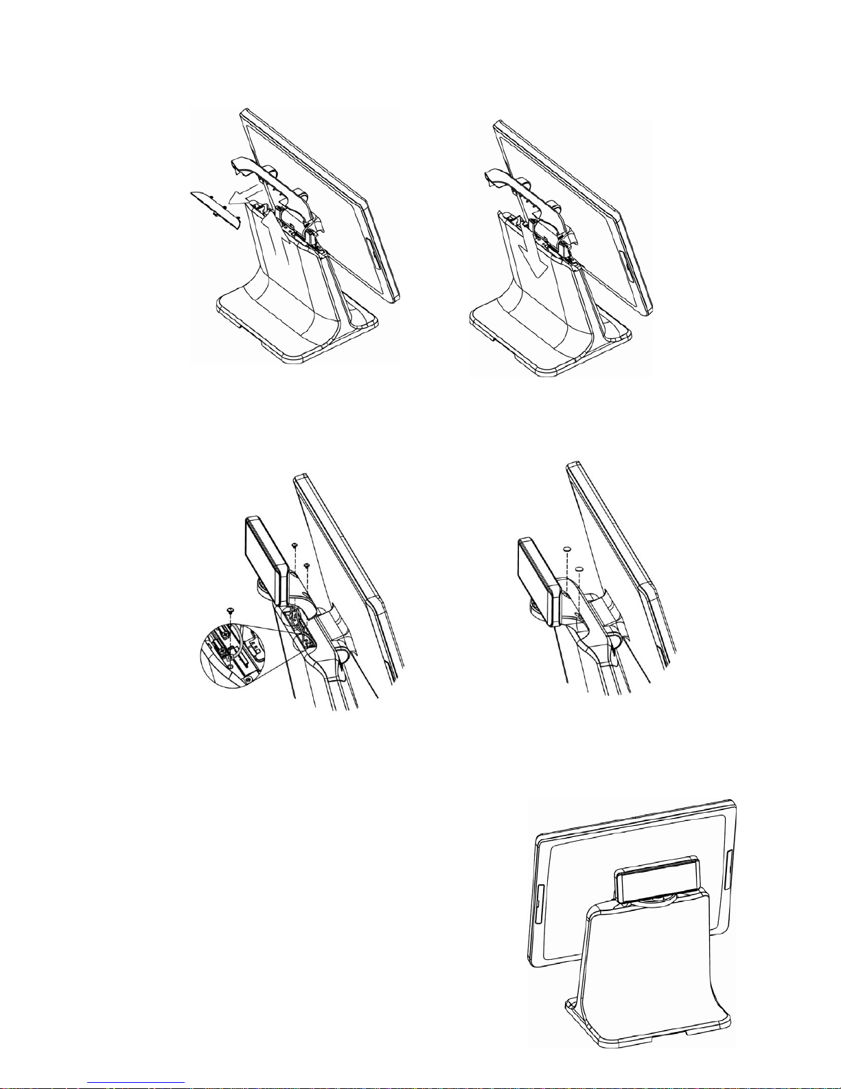
4-3 Install the Customer Display
1. Use both hands to pull the top cover of the stand upwards.
2. Release the plastic plate from the top cover.
3. Connect the customer display cable (x1) to the connector on system side
and fasten the ground cable (x1) with a M3*4 screw.
4. Put the top cover of the stand back to the postion.
5. Attach the customer display and fasten the M4 screws (x2).
6. Cover the screw holes by the rubber pads (x2).
①
②
Page 16
10
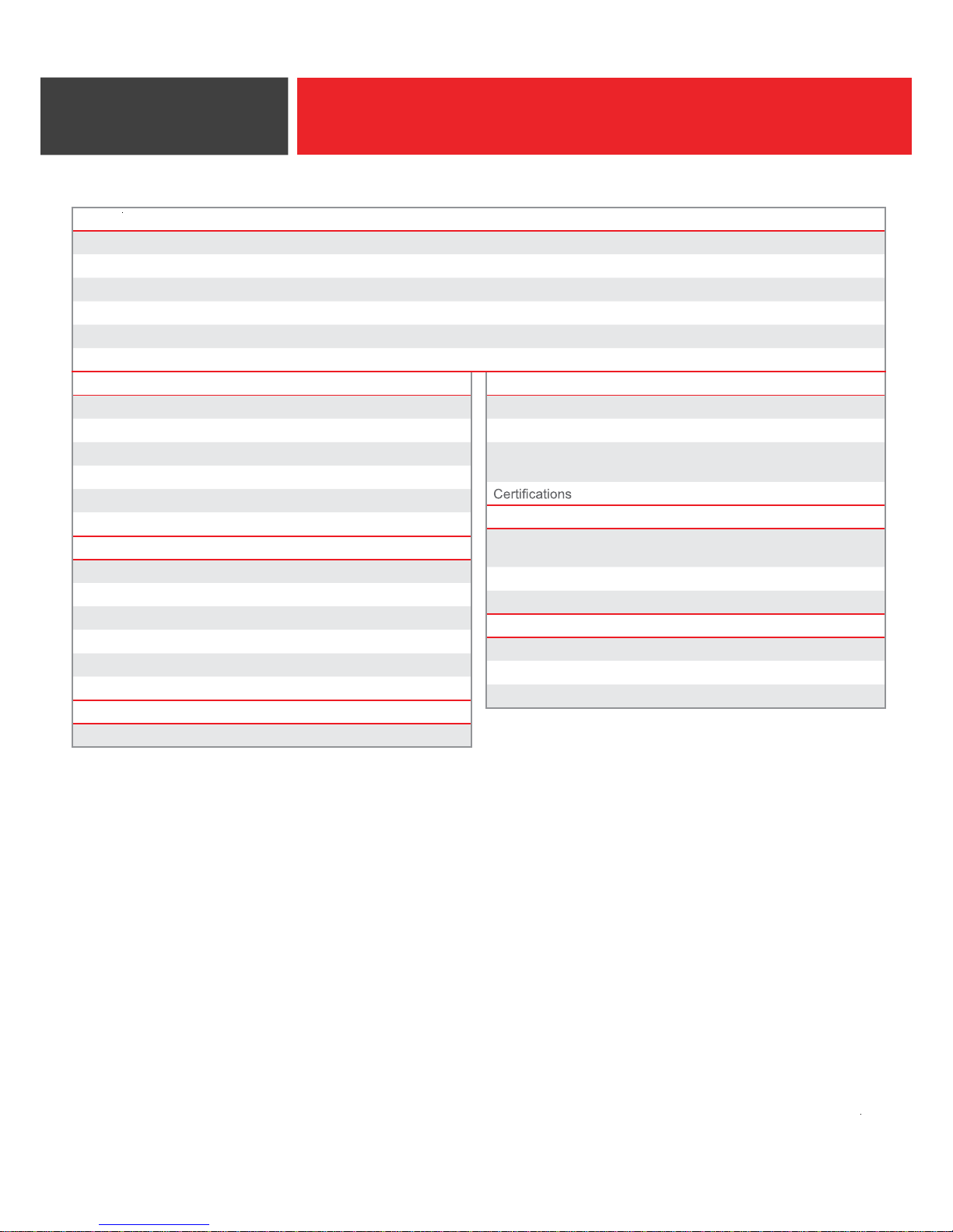
Specification
5
PART NUMBER ION-TM3A
Panel Size 15″ (381mm) TFT Active Matrix Display
Bezel Type Standard
Touch Screen 5-Wire Resistive, 50 millions taps per location
Max Resolution 1024 X 768
Dimensions (WxDxH) 14.17″ x 8.26″ x 14.17″ (360mm x 210mm x 360mm)
Weight 11 lbs (5 kg)
PHYSICAL
USB 1x USB 2.0 (Type B to PC)
Serial 0
Tilt Angle 40° to 90°
Housing Color Black
Stand Style Cable Management Base
Mounting Options Desktop Placement
DISPLAY
Video Interface Analog RGB (VGA)
Brightness 250 nits
Colors 16.7 million colors
Controls Power on/off, auto tune
Viewing Angle 160°
Housing ABS Housing
ELECTRICAL
Adapter Output 36W, 12V, 3A
ENVIRONMENTAL
Operating Temperature 32°F to 104°F (0°C to 40°C)
Humidity 20% to 80% Non-condensing
Warranty
3-year warranty with free *2-day
Advance Exchange Service
FCC Class A, CE, LVD, RoHs, NOM
OPTIONAL ACCESSORIES
ION-MR3
3-Track MSR with USB interface for
ION Fit Series
ION-RD3-LCM Integrated Rear Display, LCM
ION-BR3 Integrated Biometric Reader
WARRANTY EXTENSION AND UPGRADES
ZWE-TMC 2-Year Warranty Extension
ZOE-TMC3 *3-Year Overnight Exchange
ZOE-TMC5 *5-Year Overnight Exchange
*Available in USA and Canada
Page 17
11
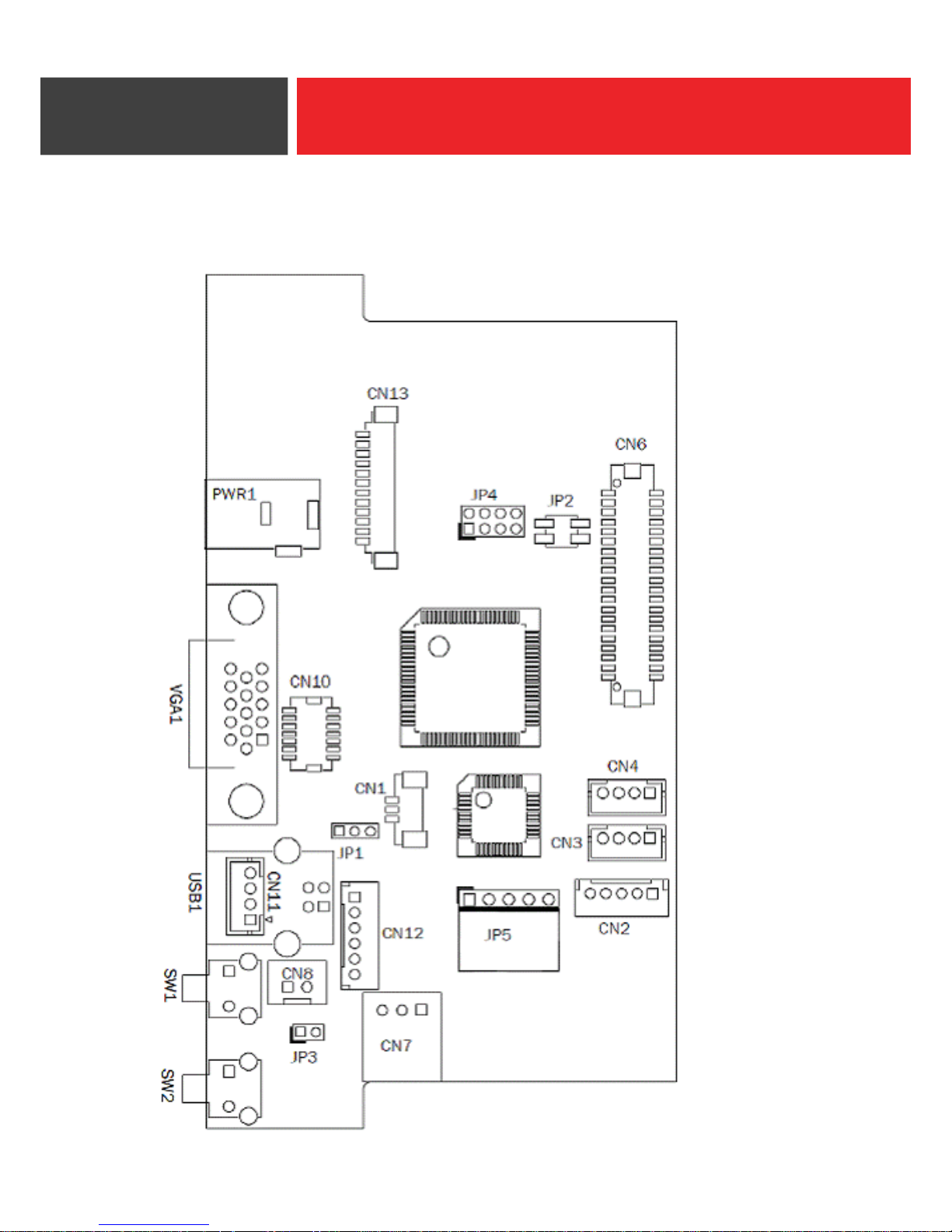
6-1 Motherboard Layout
Jumper Settings
6
Page 18

12
6-2 Connectors and Functions
Connector Function
CN1 Debug
CN2 USB connector(down-stream)
CN3 USB connector(down-stream)
CN4 USB connector(down-stream)
CN6 LVDS connector
CN7 OSD On/Off LED
CN8 Power switch
CN10 Internal VGA input connector
CN11 USB connector (upstream)
CN12 Keypad connector
CN13 Inverter connector
SW1 Power On/ Off Button
SW2 Auto tune button
USB1 USB connector (upstream)
VGA1 VGA input
PWR1 +12 input
JP1 Touch select
JP2 Inverter select
JP3 Power mode setting
JP4 Panel ID setting
JP5 Touch sensor
Page 19
13
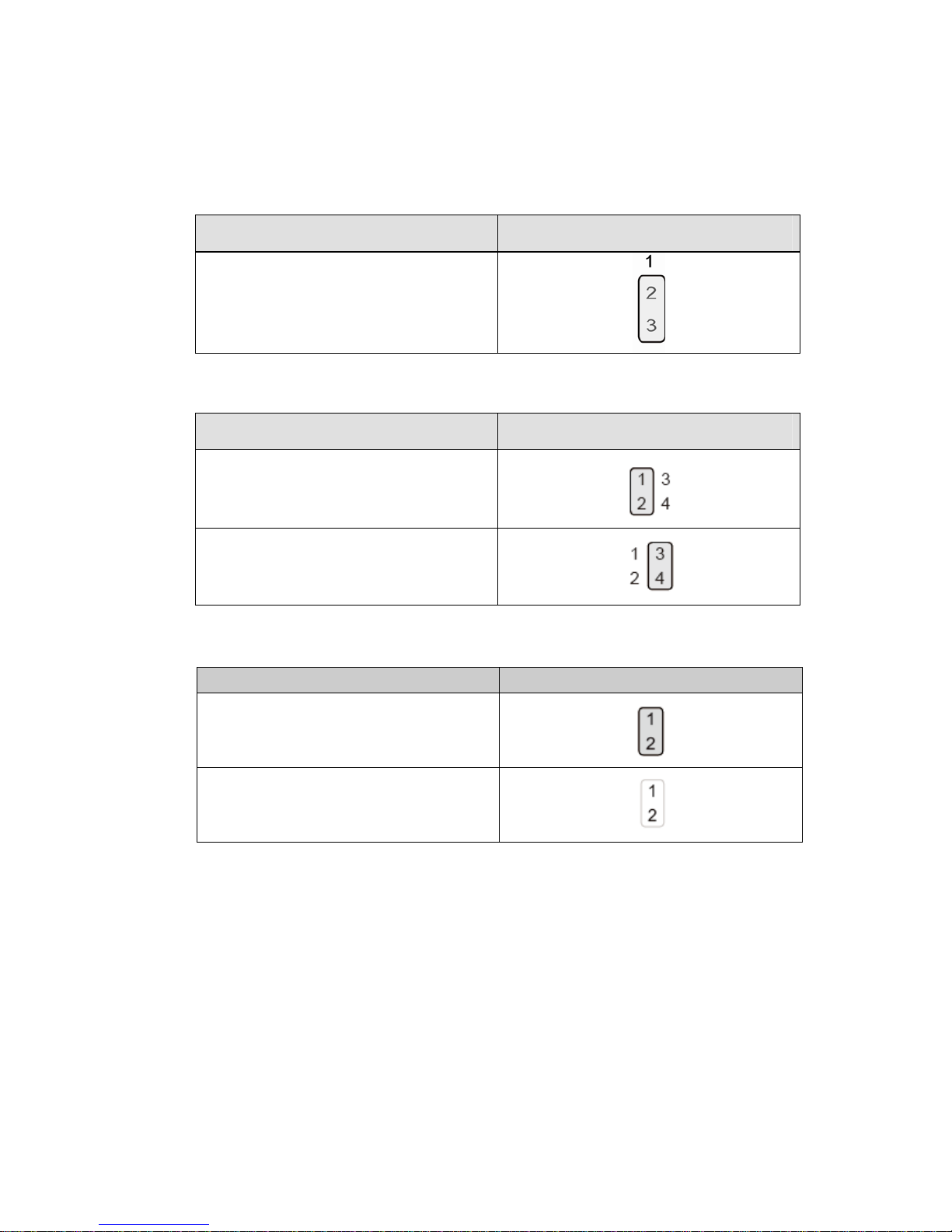
6-3 Jumper Settings
Touch Select
Function
JP1
(1-2-3)
ELO
Inverter Selection
Function
JP2
(1-2) (3-4)
▲LED
CCFL
Power Mode Setting
Function JP3 (1-2)
▲Power on
Power off
Page 20
14
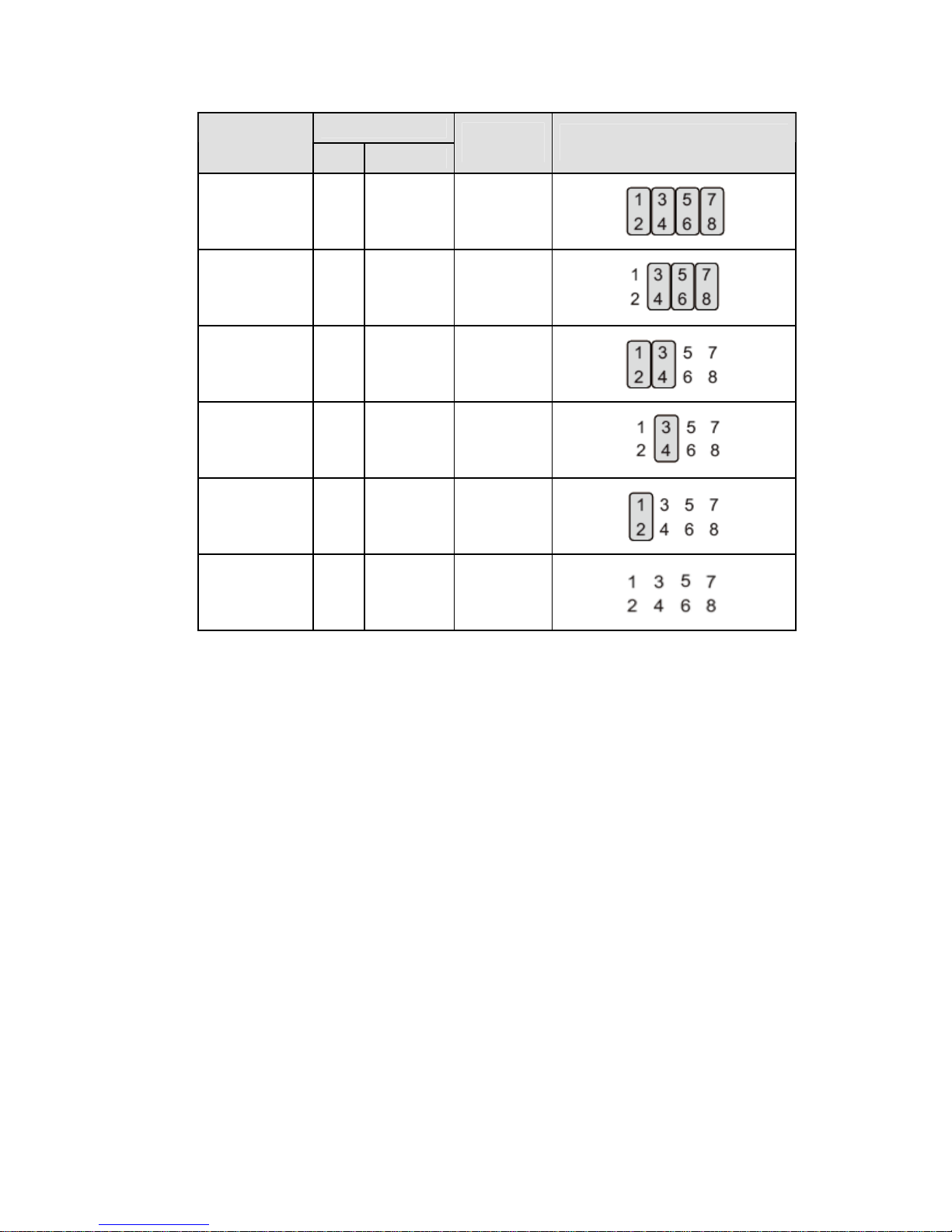
LCD ID Setting
LVDS
Resolution
Bits Channel
Output
Interface
JP4
(1-2) (3-4) (5-6) (7-8)(9-10)
1024 x 768 24 Single LVDS
800 x 600 24 Single LVDS
1280 x 1024 24 Dual LVDS
1366 x 768 24 Single LVDS
1366 x 768 18 Single LVDS
1920 x 1080 24 Dual LVDS
Page 21

15
The shipping package includes a Driver CD. You can find every individual driver and
utility that enables you to install the drivers in the Driver CD.
Please inse
“index.htm” to pick the model and required driver. For more information please visit
www.pos-x.com.
rt the Driver CD into a computer with a disk drive and double click on the
Appendix: Driver Installation
1975 Midway Lane, Suite O
Bellingham, WA 98226
[email protected]
360.738.8433
www.pos-x.com
 Loading...