

POS-X EVO-TP4 User Manual
USER MANUAL
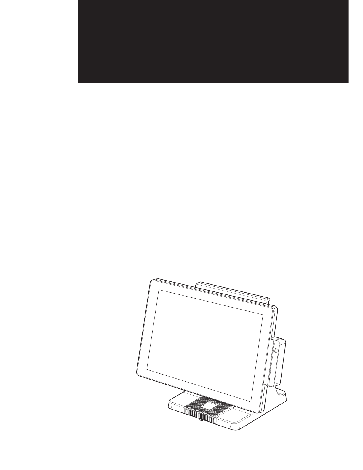
EVO-TP4
Hardware System
VERSION V1.0 November 2010

ii
Copyright 2010 November
All Rights Reserved
Manual Version 1.0
Part Number: 3LMPP4850210
The information contained in this document is subject to change without notice.
We make no warranty of any kind with regard to this material, including, but not
limited to, the implied warranties of merchantability and fitness for a particular
purpose. We shall not be liable for errors contained herein or for incidental or
consequential damages in connection with the furnishing, performance, or use of
this material.
This document contains proprietary information that is protected by copyright. All
rights are reserved. No part of this document may be photocopied, reproduced
or translated to another language without the prior written consent of the
manufacturer.
TRADEMARK
Intel®, Pentium® and MMX are registered trademarks of Intel® Corporation.
Microsoft® and Windows® are registered trademarks of Microsoft Corporation.
Other trademarks mentioned herein are the property of their respective owners.
Safety
IMPORTANT SAFETY INSTRUCTIONS
To disconnect the machine from the electrical power supply, turn off the power 1.
switch and remove the power cord plug from the wall socket. The wall socket must
be easily accessible and in close proximity to the machine.
Read these instructions carefully. Save these instructions for future reference.2.
Follow all warnings and instructions marked on the product.3.
Do not use this product near water.4.
Do not place this product on an unstable cart, stand, or table. The product may fall, 5.
causing serious damage to the product.
Slots and openings in the cabinet and the back or bottom are provided for 6.
ventilation to ensure reliable operation of the product and to protect it from
overheating. These openings must not be blocked or covered. The openings
should never be blocked by placing the product on a bed, sofa, rug, or other
similar surface. This product should never be placed near or over a radiator or heat
register or in a built-in installation unless proper ventilation is provided.
This product should be operated from the type of power indicated on the marking 7.
label. If you are not sure of the type of power available, consult your dealer or local
power company.
Do not allow anything to rest on the power cord. Do not locate this product where 8.
persons will walk on the cord.
Never push objects of any kind into this product through cabinet slots as they 9.
may touch dangerous voltage points or short out parts that could result in a re or
electric shock. Never spill liquid of any kind on the product.
iii
CE MARK
This device complies with the requirements of the EEC directive 2004/108/EC with
regard to “Electromagnetic compatibility” and 2006/95/EC “Low Voltage Directive”.
FCC
This device complies with part 15 of the FCC rules. Operation is subject to the
following two conditions:
(1) This device may not cause harmful interference.
(2) This device must accept any interference received, including interference that
may cause undesired operation.
CAUTION ON LITHIUM BATTERIES
There is a danger of explosion if the battery is replaced incorrectly. Replace only
with the same or equivalent type recommended by the manufacturer. Discard used
batteries according to the manufacturer’s instructions.
Battery Caution
Risk of explosion if battery is replaced by an incorrectly type. Dispose of used
battery according to the local disposal instructions.
Safety Caution
Note: To comply with IEC60950-1 Clause 2.5 (limited power sources, L.P.S)
related legislation, peripherals shall be 4.7.3.2 “Materials for re enclosure”
compliant.
4.7.3.2 Materials for re enclosures
For MOVABLE EQUIPMENT having a total mass not exceeding 18kg.the material
of a FIRE ENCLOSURE, in the thinnest signicant wall thickness used, shall be of
V-1 CLASS MATERIAL or shall pass the test of Clause A.2.
For MOVABLE EQUIPMENT having a total mass exceeding 18kg and for all
STATIONARY EQUIPMENT, the material of a FIRE ENCLOSURE, in the thinnest
signicant wall thickness used, shall be of 5VB CLASS MATERIAL or shall pass the
test of Clause A.1

iv
LEGISLATION AND WEEE SYMBOL
2002/96/EC Waste Electrical and Electronic Equipment Directive on the treatment,
collection, recycling and disposal of electric and electronic devices and their
components.
The crossed dust bin symbol on the device means that it should not be disposed
of with other household wastes at the end of its working life. Instead, the device
should be taken to the waste collection centers for activation of the treatment,
collection, recycling and disposal procedure.
To prevent possible harm to the environment or human health from uncontrolled
waste disposal, please separate this from other types of wastes and recycle it
responsibly to promote the sustainable reuse of material resources.
Household users should contact either the retailer where they purchased this
product, or their local government office, for details of where and how they can
take this item for environmentally safe recycling.
Business users should contact their supplier and check the terms and conditions of
the purchase contract.
This product should not be mixed with other commercial wastes for disposal.

v
Revision History
Changes to the original user manual are listed below:
Revision Description Date
1.0 Initial release• 2010 Nov.

vi
Table of Contents
1. Packing List .............................. 1
1-1. Standard Accessories ..............................................1
1-2. Optional Accessories ...............................................2
2. System View ............................. 3
2-1. Front & Side View ....................................................3
2-2. Rear View with stand ...............................................3
2-3. I/O Ports View ..........................................................4
2-4. System Dimension ...................................................4
3. System Assembly & Disassembly 5
3-1. Stand Disassembly ..................................................5
3-2. Power Adapter Replacement ...................................5
3-3. HDD Replacement ...................................................6
3-4. Open the System .....................................................7
3-5. RAM Replacement ..................................................8
4. Peripheral Installation ............. 9
4-1. MSR Installation ......................................................9
4-2. VFD Installation ......................................................10
4-3. Second Display Installation ....................................11

vii
4-4. Wall Mount Kit Installation ......................................12
4-5. Cable Cover Installation .........................................13
4-6. Cash Drawer Installation ........................................14
5. Specications ......................... 16
6. Jumper Setting ........................ 17
6-1. For C48 Motherboard .............................................17
6-1-1
.
Motherboard Layout ................................................ 17
6-1-2.
Connectors & Functions .......................................... 19
6-1-3
.
Jumper & BIOS/Utility Setting .................................20
6-2.
For B68 Motherboard .............................................25
6-2-1.
Motherboard Layout ................................................ 25
6-2-2.
Connectors & Functions .......................................... 26
6-2-3.
Jumper Setting ........................................................ 27
Appendix: Drivers Installation .... 30

viii
The page is intentionally left blank.

1
Packing List1.
Standard Accessories
1-1.
System (with stand)a.
Driver bankb.
Power adapterc.
Power cordd.
RJ45-DB9 cable (x3)e.
a
b
c
d
e
2
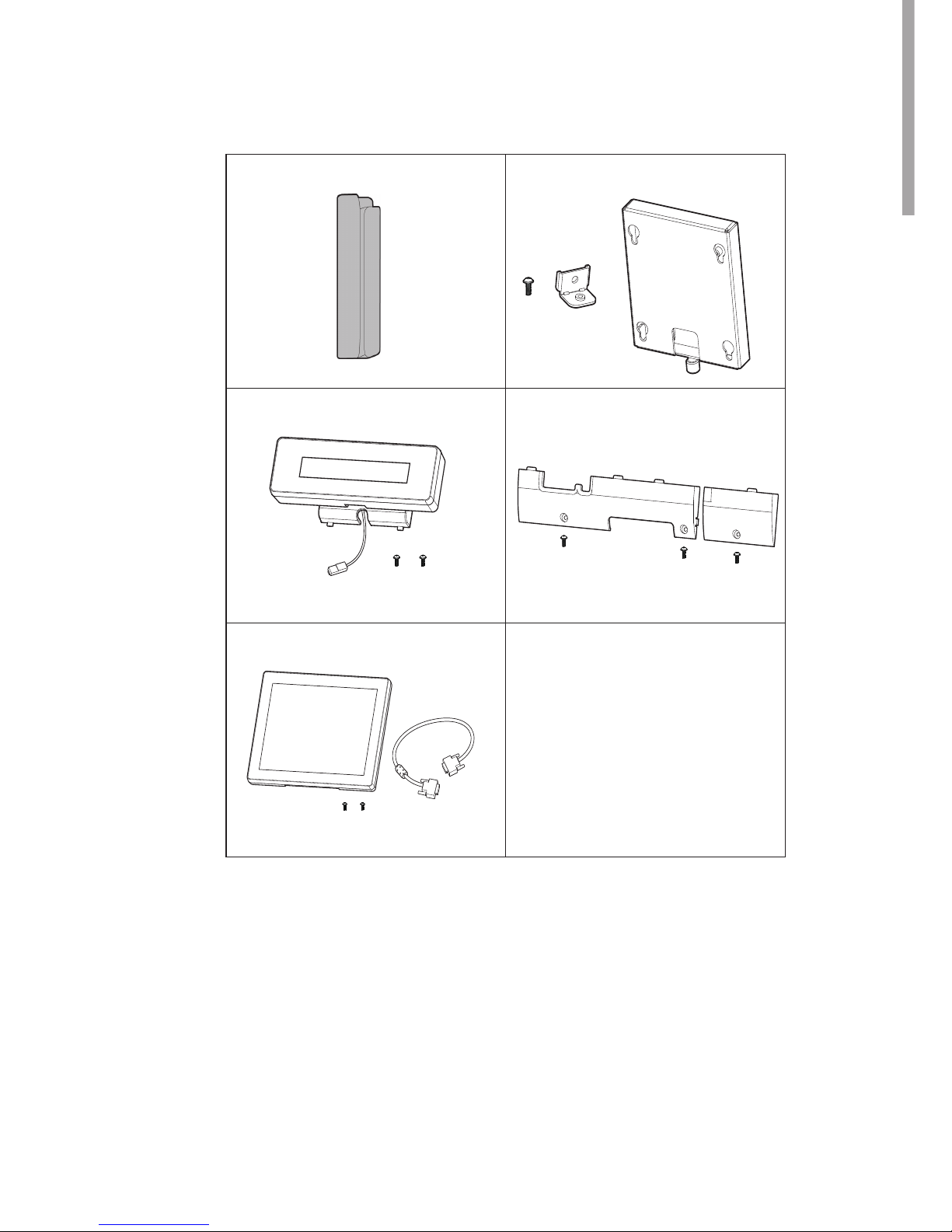
Optional Accessories
1-2.
MSR Modulea.
VFD Module (with RJ-45 cable)b.
Second Display (with VGA cable)c.
Wall Mount Kitd.
Cable Covere.
a
b
c
d
e

3
System View2.
Front & Side View
2-1.
Item No. Description
1 Touch screen
2 MSR module (optional)
3 Rugged footprint
4 Ventilation
5 HDD door
Rear View with stand
2-2.
Item No. Description
6 VFD dummy cover
7 MSR dummy cover
1
2
4
3
5
6
4
2
6
7
4
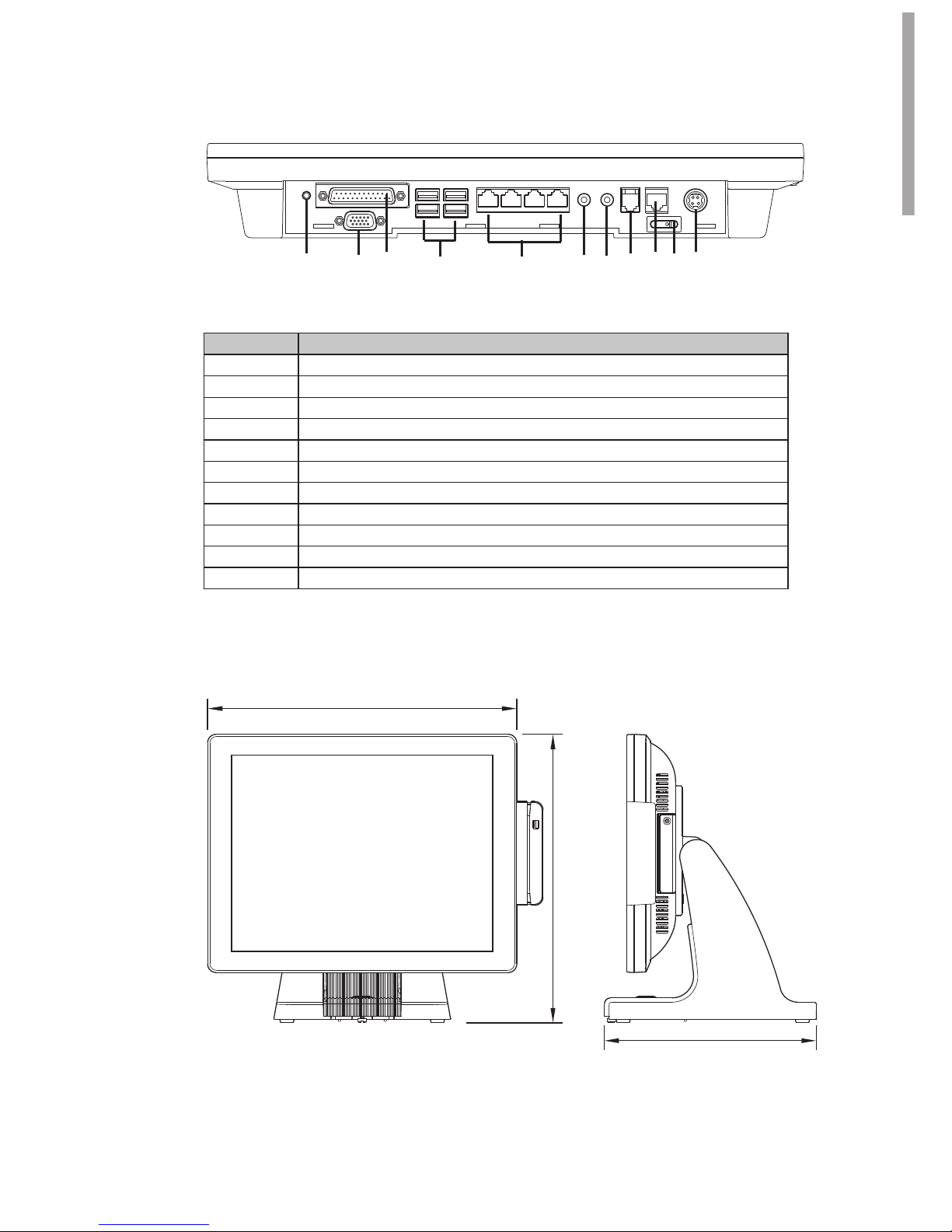
I/O Ports View
2-3.
Item No. Description
a Power Button
b 2nd VGA
c Parallel
d USB x 4
e COM 1, 2, 3, 4 (from right to left)
f Line-out
g Mic-in
h Cash Drawer
i LAN
j Power Switch
k DC-IN
a
b
c
d
e
f
g
h
i j
k
System Dimension
2-4.
248mm
361mm
337mm
 Loading...