

Page 1
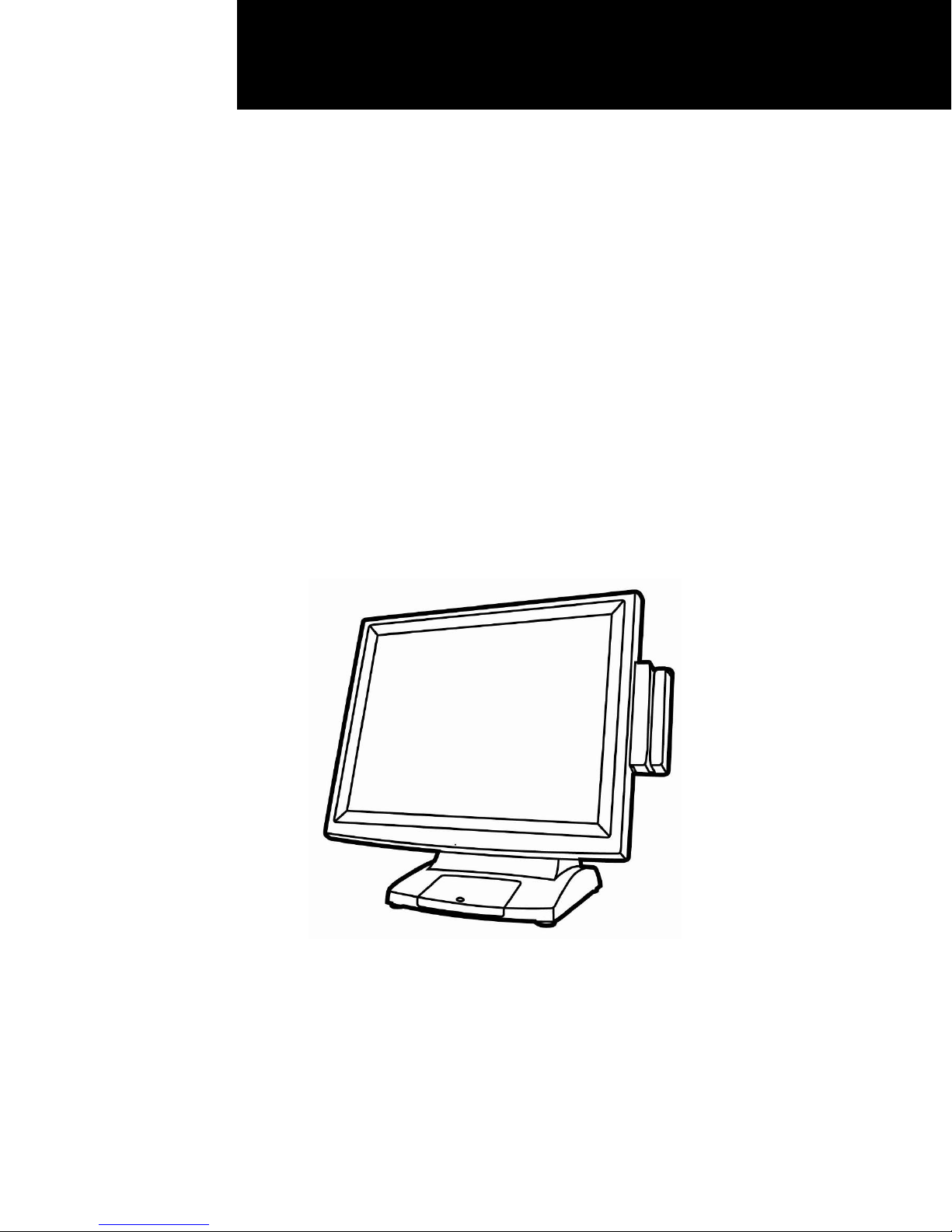
User Manual
Revision v1.2 November 2009
EVO-TM2
Hardware
System
Page 2

Copyright 2009 February
All Rights Reserved
Manual Version 1.1
Part Number:
The information contained in this document is subject to change without notice.
We make no warranty of any kind with regard to this material, including, but not
limited to, the implied warranties of merchantability and fitness for a particular
purpose. We shall not be liable for errors contained herein or for incidental or
consequential damages in connection with the furnishing, performance, or use of
this material.
This document contains proprietary information that is protected by copyright. All
rights are reserved. No part of this document may be photocopied, reproduced or
translated to another language without the prior written consent of the
manufacturer.
TRADEMARK
Intel®, Pentium® and MMX are registered trademarks of Intel® Corporation.
Microsoft® and Windows® are registered trademarks of Microsoft Corporation.
Other trademarks mentioned herein are the property of their respective owners.
ii
Page 3

Safety
IMPORTANT SAFETY INSTRUCTIONS
1. To disconnect the machine from the electrical Power Supply, turn off the power
switch and remove the power cord plug from the wall socket. The wall socket
must be easily accessible and in close proximity to the machine.
2. Read these instructions carefully. Save these instructions for future reference.
3. Follow all warnings and instructions marked on the product.
4. Do not use this product near water.
5. Do not place this product on an unstable cart, stand, or table. The product may fall,
causing serious damage to the product.
6. Slots and openings in the cabinet and the back or bottom are provided for
ventilation; to ensure reliable operation of the product and to protect it from
overheating. These openings must not be blocked or covered. The openings
should never be blocked by placing the product on a bed, sofa, rug, or other
similar surface. This product should never be placed near or over a radiator or
heat register, or in a built-in installation unless proper ventilation is provided.
7. This product should be operated from the type of power indicated on the marking
label. If you are not sure of the type of power available, consult your dealer or
local power company.
8. Do not allow anything to rest on the power cord. Do not locate this product where
persons will walk on the cord.
9. Never push objects of any kind into this product through cabinet slots as they may
touch dangerous voltage points or short out parts that could result in a fire or
electric shock. Never spill liquid of any kind on the product.
CE MARK
This device complies with the requirements of the EEC directive
2004/108/EC with regard to “Electromagnetic compatibility” and 2006/95/EC
“Low Voltage Directive”
FCC
This device complies with part 15 of the FCC rules. Operation is subject to the
following two conditions:
(1) This device may not cause harmful interference.
(2) This device must accept any interference received, including interference that
may cause undesired operation
iii
Page 4
CAUTION ON LITHIUM BATTERIES
There is a danger of explosion if the battery is replaced incorrectly. Replace only with
the same or equivalent type recommended by the manufacturer. Discard used
batteries according to the manufacturer’s instructions.
LEGISLATION AND WEEE SYMBOL
2002/96/EC Waste Electrical and Electronic Equipment Directive on the treatment,
collection, recycling and disposal of electric and electronic devices and their
components.
The crossed dustbin symbol on the device means that it should not be disposed of
with other household wastes at the end of its working life. Instead, the device
should be taken to the waste collection centers for activation of the treatment,
collection, recycling and disposal procedure.
To prevent possible harm to the environment or human health from uncontrolled
waste disposal, please separate this from other types of wastes and recycle it
responsibly to promote the sustainable reuse of material resources.
Household users should contact either the retailer where they purchased this
product, or their local government office, for details of where and how they can
take this item for environmentally safe recycling.
Business users should contact their supplier and check the terms and conditions of
the purchase contract.
This product should not be mixed with other commercial wastes for disposal.
iv
Page 5

Table Contents
1 Package Checklist.......................................1
1-1 Standard Items....................................................................... 1
1-2 Optional Items........................................................................ 2
2 System View ................................................3
2-1 Front View.............................................................................. 3
2-2 Rear View .............................................................................. 4
2-3 Bottom View........................................................................... 5
2-4 I/O View ................................................................................. 6
3 Peripheral Installation.................................7
3-1 MSR....................................................................................... 7
3-2 VFD........................................................................................ 8
3-3 Wall Mount Kit...................................................................... 10
4 System Assembly & Disassembly...........12
4-1 Remove the System Stand.................................................. 12
4-2 Remove the LCD Rear Cover & the EMI Cover ............ Error!
Bookmark not defined.
4-3 Replace the Power Adapter................................................. 13
4-4 Replace the AD Board...........Error! Bookmark not defined.
4-5 Replace the Inverter Board....Error! Bookmark not defined.
4-6 Replace the LCD Front BezelError! Bookmark not defined.
5 Specification..............................................14
6 Jumper Settings........................................15
6-1 Connectors and Functions................................................... 15
6-2 Motherboard Layout ............................................................ 16
6-3 Jumper Setting..................................................................... 17
v
Page 6
1 Package Checklist
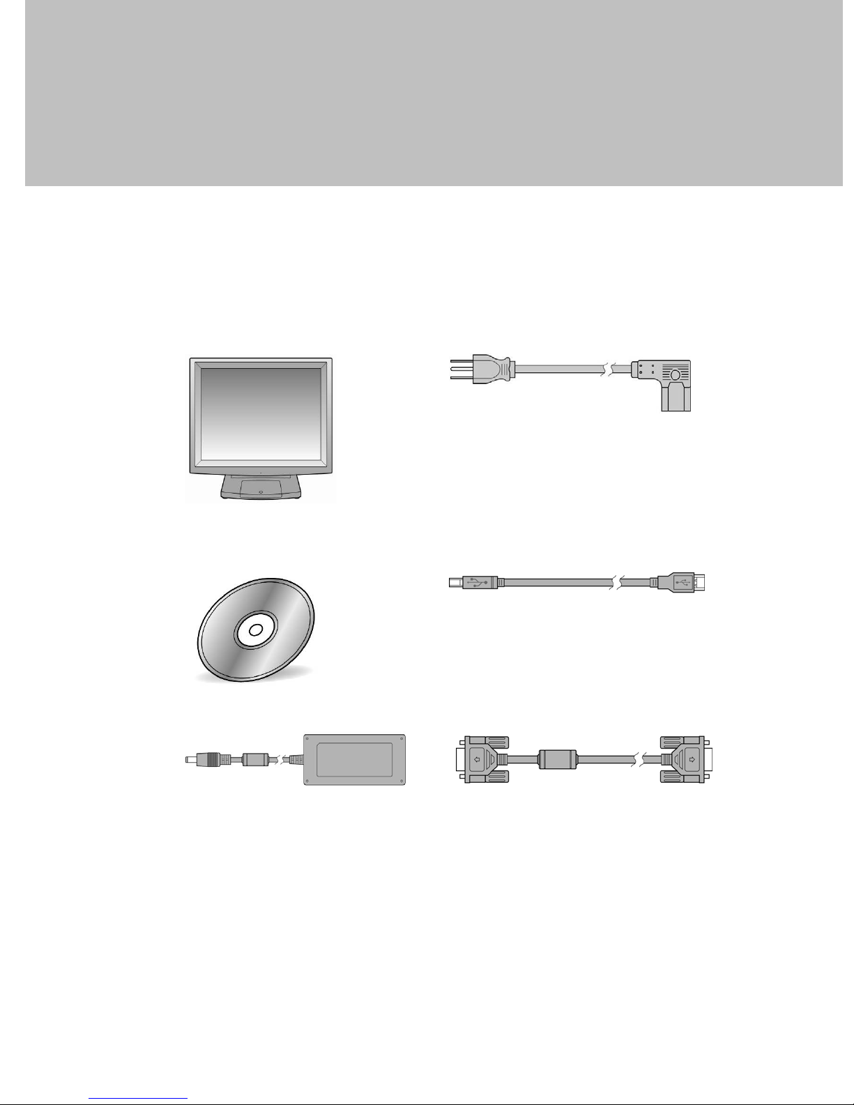
Take the system unit out of the carton. Remove the unit from the carton by holding
it by the foam inserts. The following contents should be found in the carton:
1-1 Standard Items
a.
b.
c.
d.
e.
f.
a. Monitor
b. Driver CD
c. Power Adapter (36W)
d. Power Cable
e. USB Cable for touch
f. VGA Cable
1
Page 7
1-2 Optional Items
a.
b.
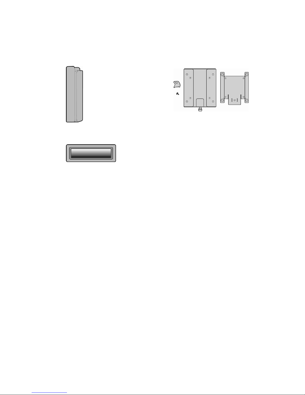
a. MSR Module
b. VFD Module
c. Wall Mount Kit
c.
2
Page 8
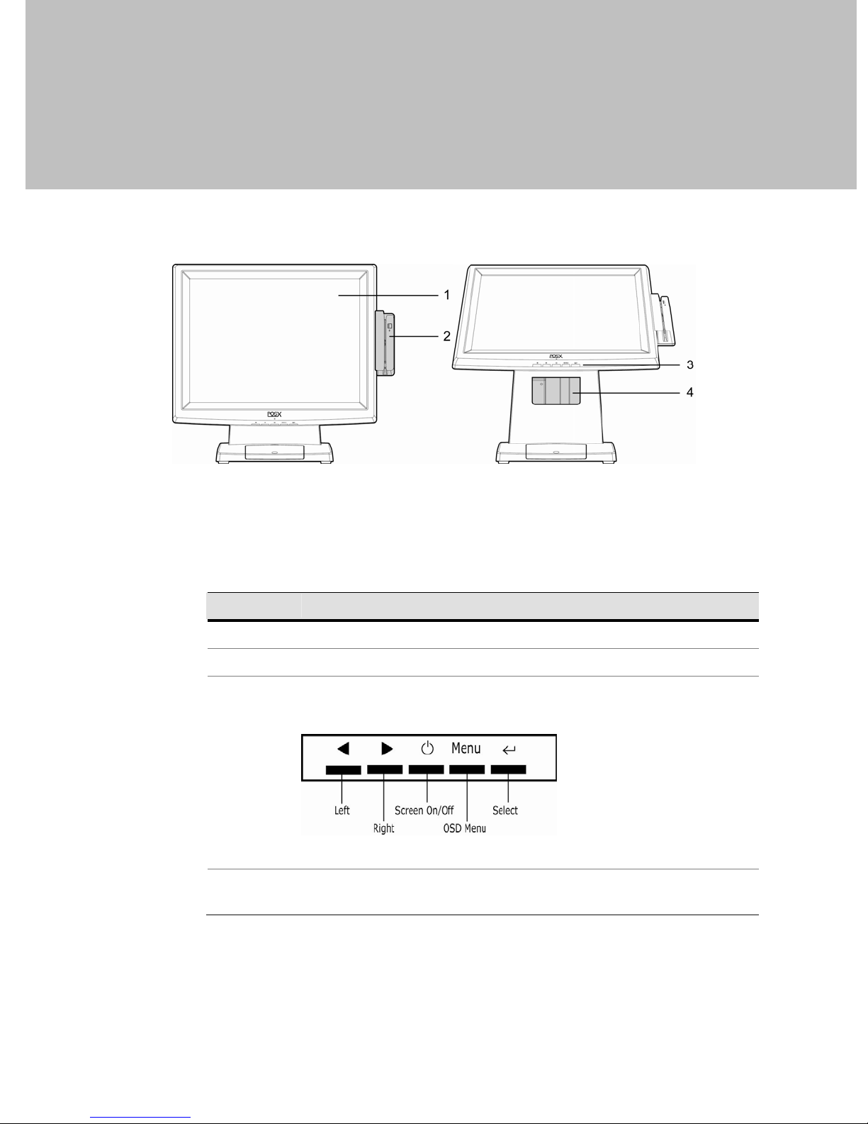
2 System View
2-1 Front View
System Overview table -1
Number Component
1 Touch Screen
2 MSR (Option)
OSD Button for OSD menu selection
From left to right button:
3
4 Stand Hole for cable management
3
Page 9
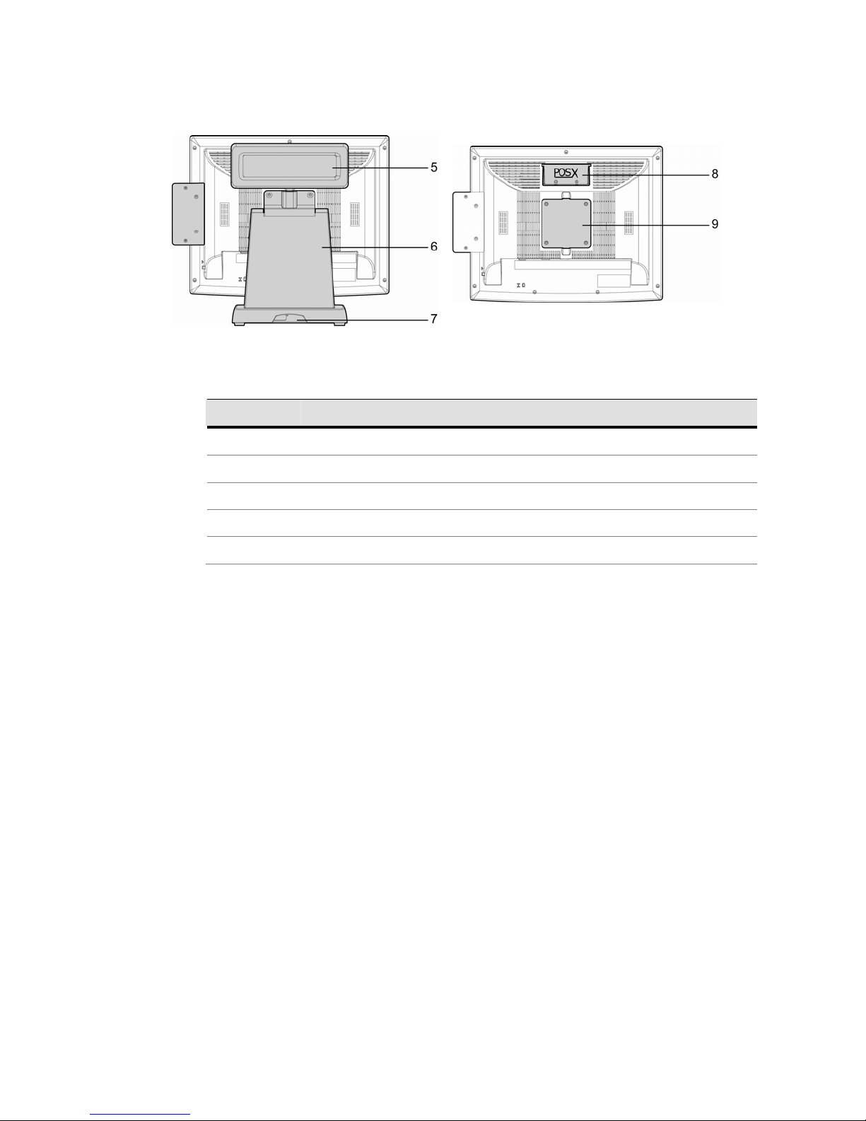
2-2 Rear View
System Overview table -2
Number Component
5 VFD Module (option)
6 Stand (with cable management and power adapter holder bracket)
7 Cable Outlet
8 VFD Cover (VFD module installation location)
9 VESA hole for stand and wall-mount kit installation
4
Page 10
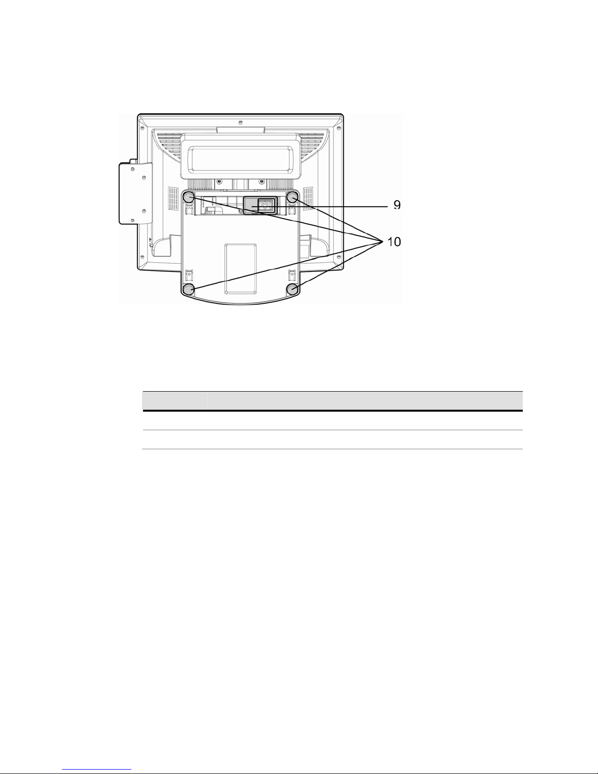
2-3 Bottom View
System Overview table -3
Number Component
9 Easy-Service Retaining Bracket for Power Adapter
10 Rubber feet
5
Page 11
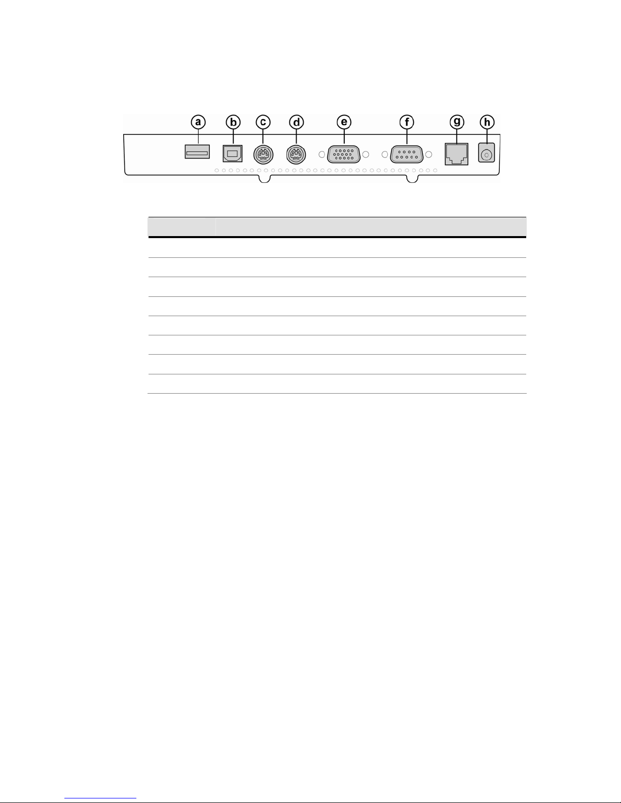
2-4 I/O View
System Overview table -4
Number Component
a USB (to Device)
b USB IN (from PC)
c PS/2 OUT
d PS/2 IN
e VGA IN
f COM IN
g COM 12V
h 12V IN
6
Page 12
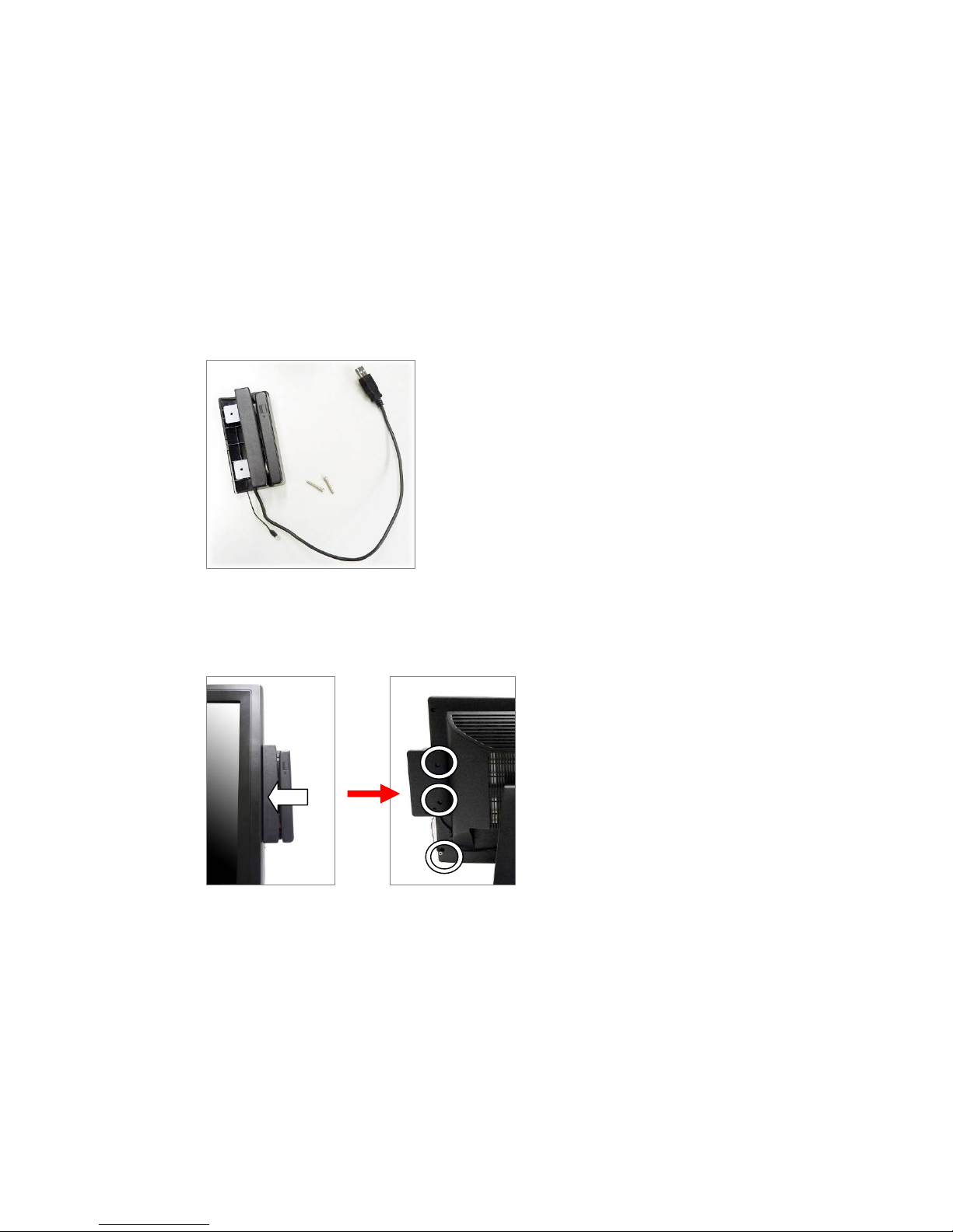
3 Peripheral Installation
g
3-1 MSR
Components of MSR Kit:
MSR
Groundin
USB
Screws
1. Slide the MSR in from the right side of the System.
2. Fasten the screws (x2) and grounding cable (x1).
7
Page 13
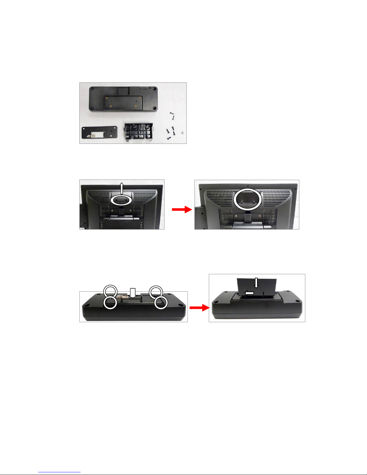
3-2 VFD
Components of VFD Kit:
VFD
Metal Bracket
1. Unfasten the screws (x2) and slide the VFD Cover upward.
Plastic bracket
Screws
2. Positioning the VFD metal bracket onto the rear side of the VFD module
and fasten the screws (x4).
3. Place the plastic bracket onto the metal bracket in the direction show.
8
Page 14
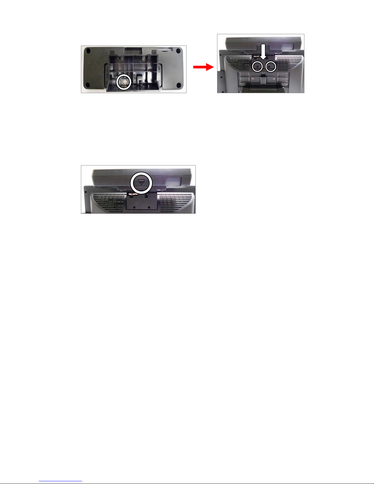
4. Fasten the screw (x1) to fix the plastic bracket to the metal bracket and
VFD module.
5. Slide the MSR module with bracket into the VFD socket.
6. Attach the MSR module by fastening the screws (x2).
7. Connect the RJ45 connector of VFD cable to the VFD Module.
8. Connect the other end of VFD Cable (COM Connector) to port G(see 2-4)
9
Page 15
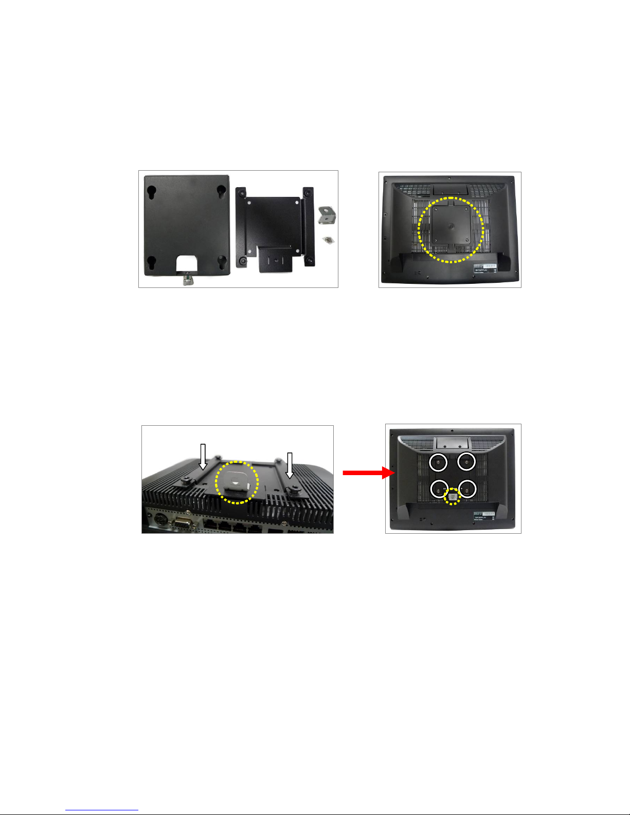
3-3 Wall Mount Kit
Before installing the Wall Mount Kit, remove the stand first.
(See Chapter 4-1)
(Wall Mount Kit) (Place to install)
a. Wall Plate
1. Components of VESA-standard wall mount kit include following.
a. Wall-mount plate
b. Monitor-mount plate & screws
c. Screw metal bracket
2. The wall mount Kit installation is at the rear side of the system.
b. Monitor
c
plate
b
c
3. Place “b” which has 4 fixed hooks onto the rear side of the LCD.
4. Place “c” onto the holes of the monitor plate as pictured and fasten the
screw (x1).
Fasten the screws (x4) to attach the monitor plate
10
Page 16
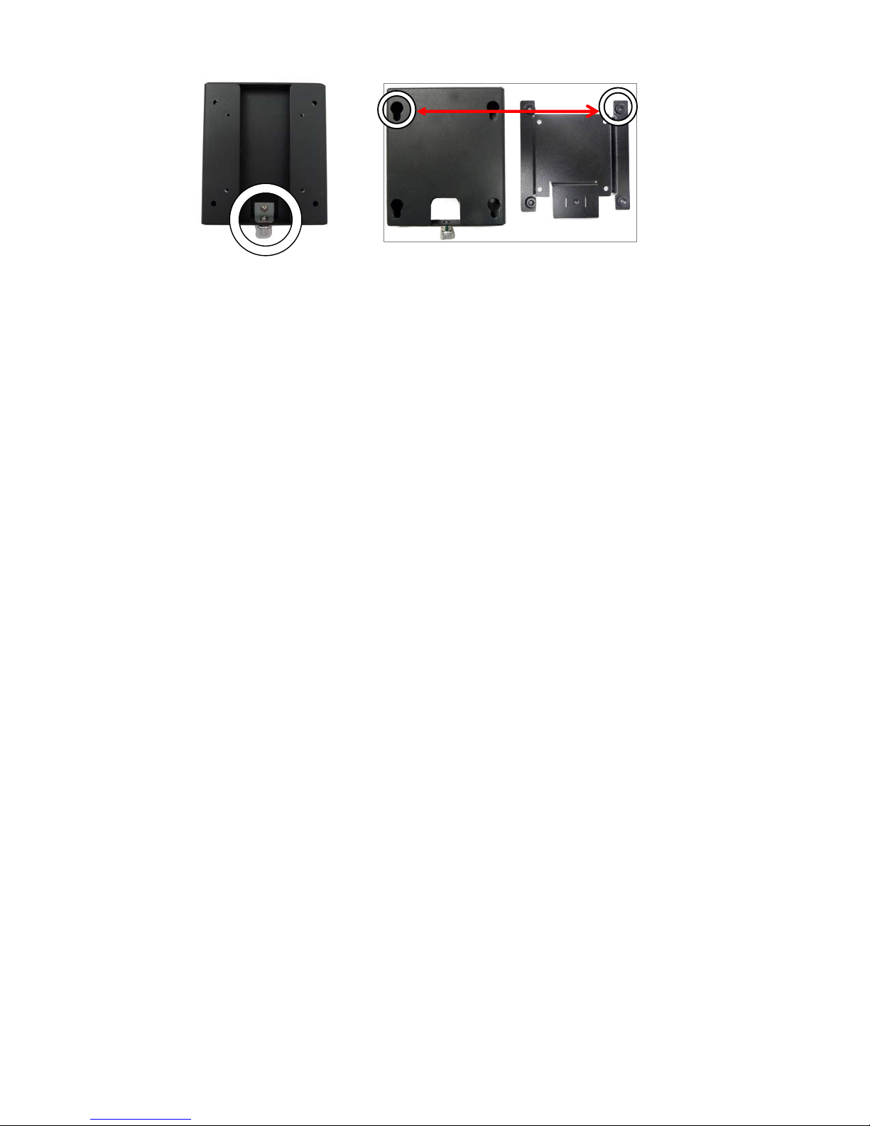
5. Attach “a” on the wall.
6. Fasten the thumb screw (x1).
7. Align the hooks of “monitor plate” into the keyholes of the “wall plate”.
11
Page 17
4 System Assembly & Disassembly
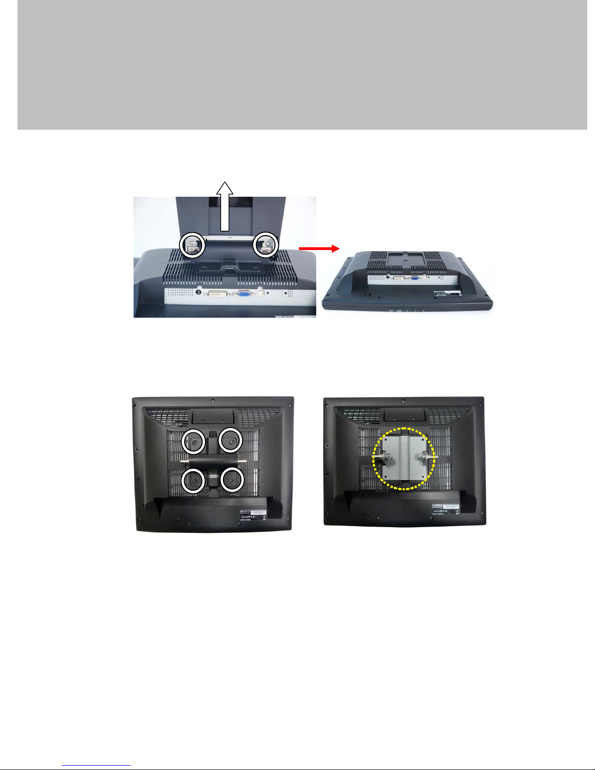
4-1 Removing the System Stand
1. Remove the screws (x2) that fasten the stand and the system.
2. Remove the screws (x4) that fasten the plastic VESA mounting plate and
the LCD rear cover.
3. Remove the VESA metal bracket,
12
Page 18
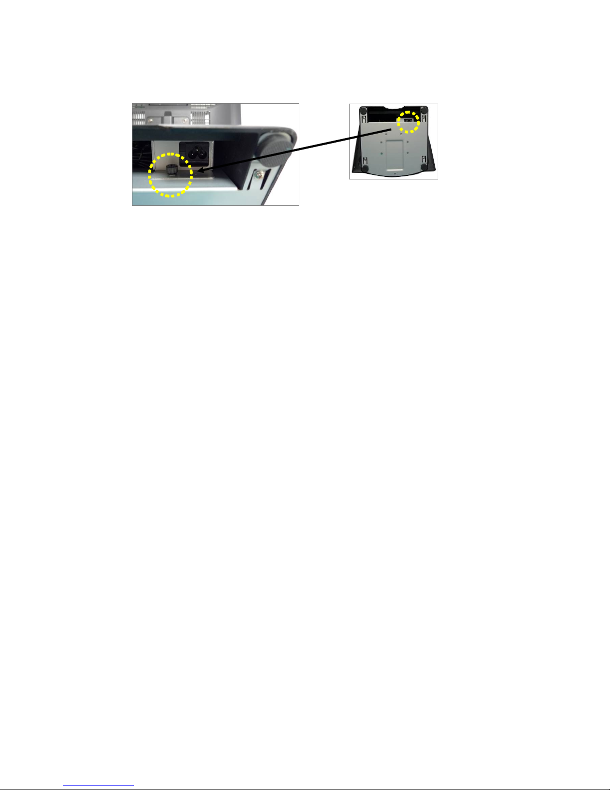
4-2 Replacing the Power Adapter
1. Release the thumb screw to seperate the retaining metal bracket from the
stand and take out the power adapter.
13
Page 19
5 Specifications
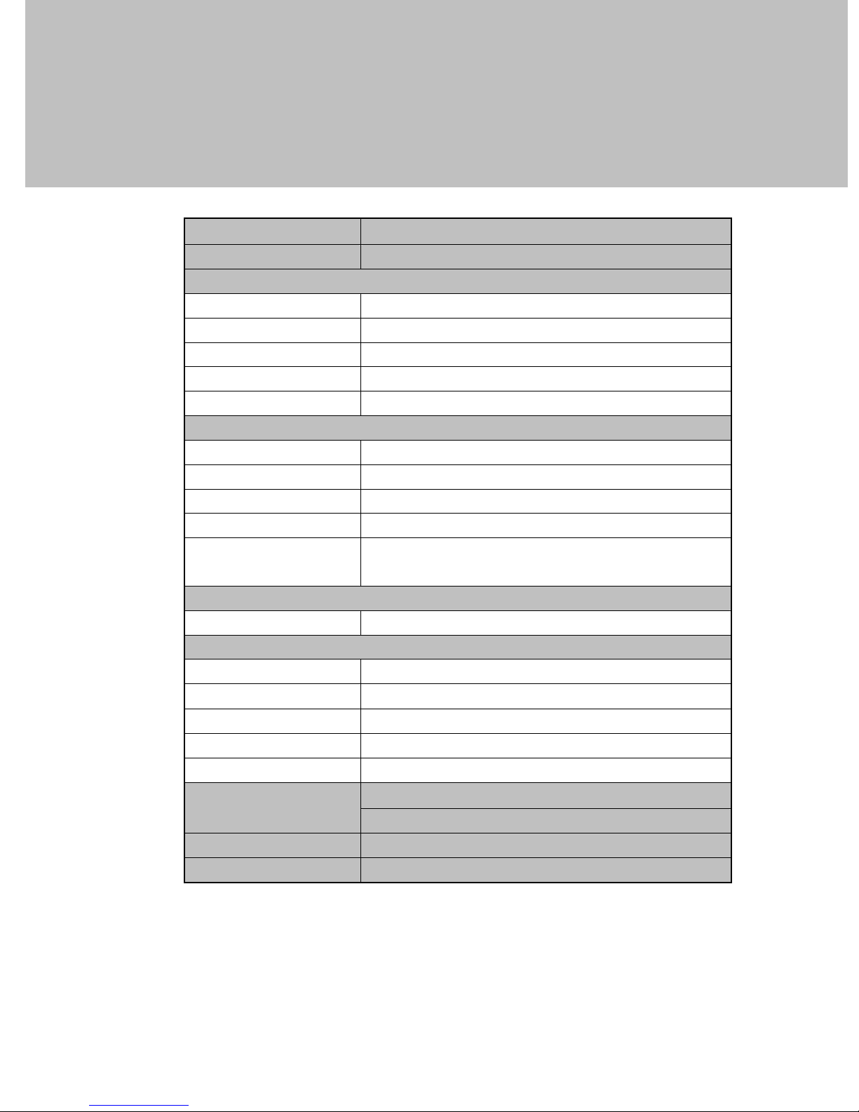
Model Name EVO-TM2
AD board B13
LCD Panel
Panel Size 15"
Brightness 250nits
Resolution 1024 x 768
Touch Resistive
Tilt Angel
External I/O Ports
VGA 1
PS/2 2 (1 x PS/2 IN to PC, 1 x PS/2 OUT to Keyboard)
OSD Button 5 (Left, Right, Power, Menu, Select)
USB 1x USB 2.0 (Type A), 1x USB 2.0 (Type B to PC)
o
0
~ 90 o
Serial / COM
Power adapter
Power Source Ext. 36W, 12V/3A
Environment
EMC & Safety FCC/CE Class A, LVD
Operating Temperature
Storage Temperature
Operating Humidity 5% to 95% RH, Non-condensing
Storage Humidity 5% to 95% RH, Non-condensing
Dimension (W x D x H)
Weight (N.W./G.W.)
Mounting
* This specification is subject to change without prior notice.
2 x COM (1 x DB-9/F type to PC,
1x RJ-45 type to VFD)
o
0
C~ 40 oC (32oF ~ 104 oF)
o
-20
C ~ 55 oC (-4 oF ~ 131 oF)
LCD 90 degree : 365.2 x 296.2 x 282.2 mm
LCD 0 degree : 365.2 x 217.76 x 343.1 mm
4.8kgs / 5.8kgs
75mm x75mm VESA Standard holes
14
Page 20

6 Jumper Settings
6-1 Connectors and Functions
Connector Purpose
CN1 LCD Interface Connector
CN2 Inverter Connector
CN3 Eturbo Touch Panel Connector
CN4 Power State LED Connector
CN5 VGA Extender Connector
CN6 Power ON/OFF Connector (Reserve)
CN8 GM2621 SPI Connector (Reserve)
CN9 Internal USB Device Connector (Down-Stream)
CN10 Internal COM Device Connector (Output)
CN11 Keypad Connector
CN12 Card Reader Connector
CN13 DVI Connector
COM1 COM Port Connector (Input)
PS1 P/S2 Input Connector
PS2 P/S2 Output Connector
PWR1 +12V Input
PWR2 +12V Input (Internal)
RJ45_1 COM Port Connector (Output)
USB1 USB Port (Down-Stream x2)
USB3 USB Port (Upstream)
VGA1 VGA Input Connector
15
Page 21
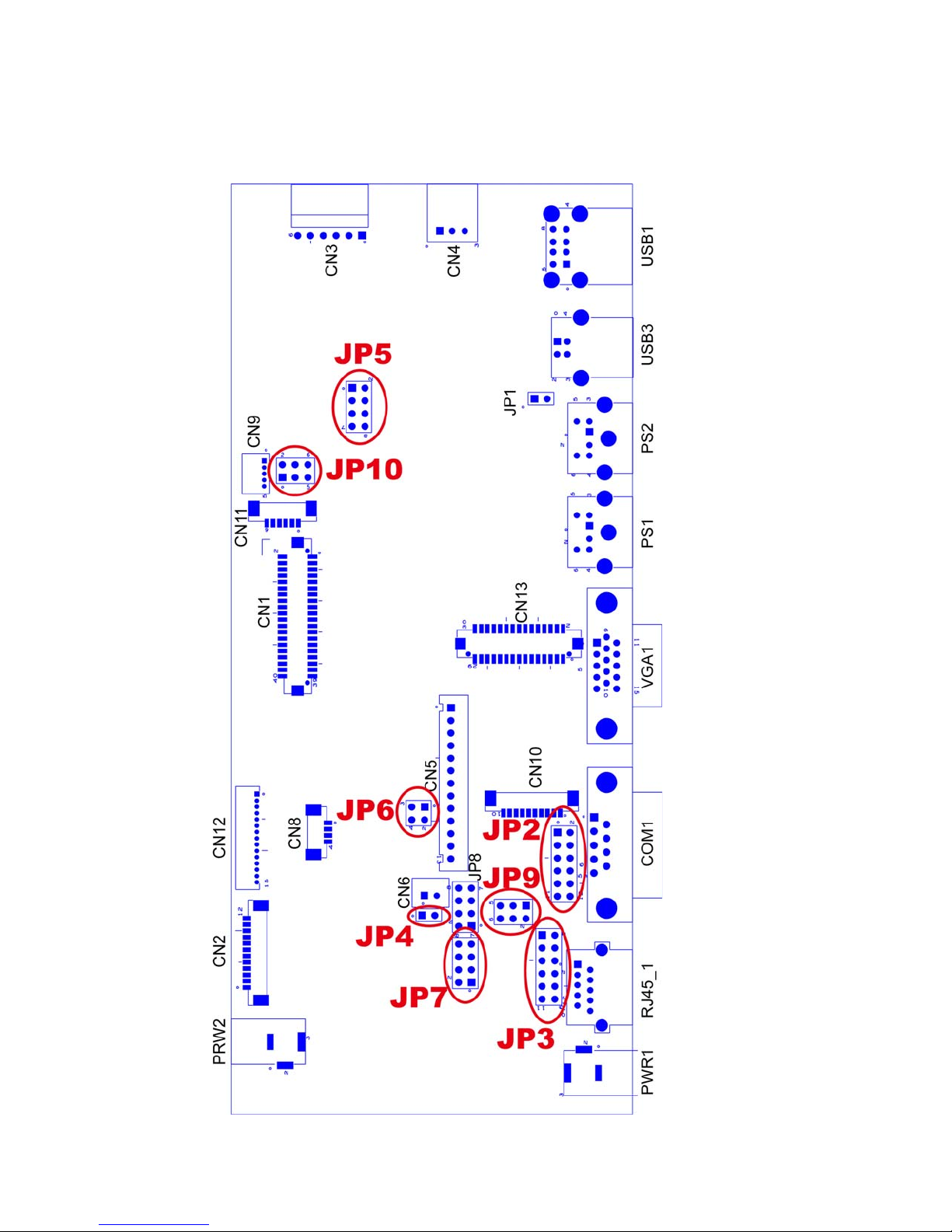
6-2 Motherboard Layout
16
Page 22
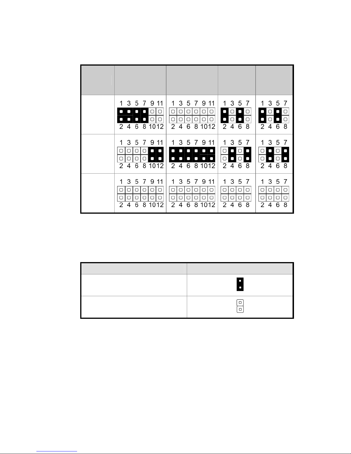
6-3 Jumper Setting
1. COM Port Setting
Function
JP2
(1-2, 3-4, 5-6,
7-8, 9-10, 11-12)
JP3
(1-2, 3-4, 5-6,
7-8, 9-10, 11-12)
JP7
(1-2, 3-4,
5-6, 7-8)
JP8
(1-2, 3-4,
5-6, 7-8)
▲RS232
Touch
RS422
Touch
Int./Ext.
COM
NOTE: It can only be selected above four functions of RS232 Touch / Internal COM
/ RS232 Card Reader / External COM in the meantime.
2. Power Mode Setting
Function / Location JP4 (1-2)
▲On
Off
▲ = Manufacturer Default setting
17
Page 23
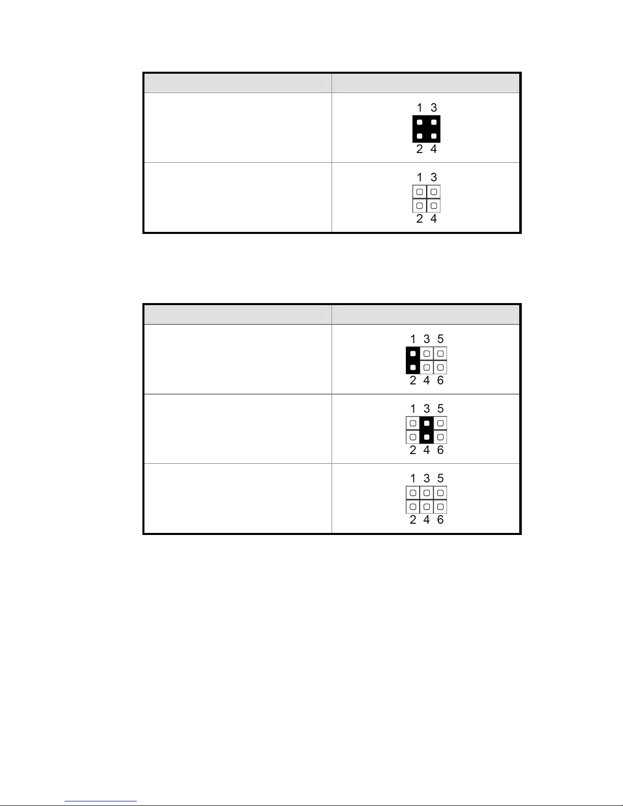
3. GM2621 SPI Setting
Function / Location JP6 (1-2, 3-4)
SPI
▲N/C
4. RJ45 COM Power Setting
Function / Location JP9 (1-2, 3-4, 5-6)
▲COM RI
COM+5V
COM+12V
▲ = Manufacturer Default setting
18
Page 24
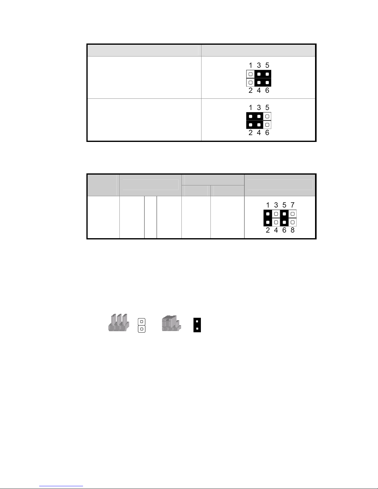
5. USB Touch Setting
Function / Location JP10 (1-3, 2-4, 3-5, 4-6)
▲On Board USB Touch
Internal USB Conn.
6. LCD ID Setting
Number
Resolution
4 1024 x 768 24 Single
▲ = Manufacturer Default setting
LVDS Panel
Bits Channel
JP3 (1-2, 3-4, 5-6, 7-8)
Note:
OPEN SHORT
19
 Loading...