

POS-X EVO-RP1-U, EVO-RP1-UE, EVO-RP1-US, EVO-RP1 User Manual

EVO-RP1
::: Receipt Printer User’s Manual :::
All specifications are subject to change without notice
1

TABLE OF CONTENTS
1. Parts Identifications 3
2. Setting up the printer 4
2.1 Unpacking 4
2.2 Connecting the cables 5
2.3 Loading the paper 8
2.4 Dip switch setting 10
3. Control panel and other functions 14
3.1 Control panel 14
3.2 Error Indicator 14
4. Self Test 15
5. Hexadecimal Dump 15
6. Specifications 16
6.1. General Specifications 18
6.2. Auto Cutter Specifications 18
6.3. Interface 18
6.4. Electrical Characteristics 18
6.5. Environmental Requirements
6.6. Reliability 19
6.7. Certification 19
7. Command List 20
19
2
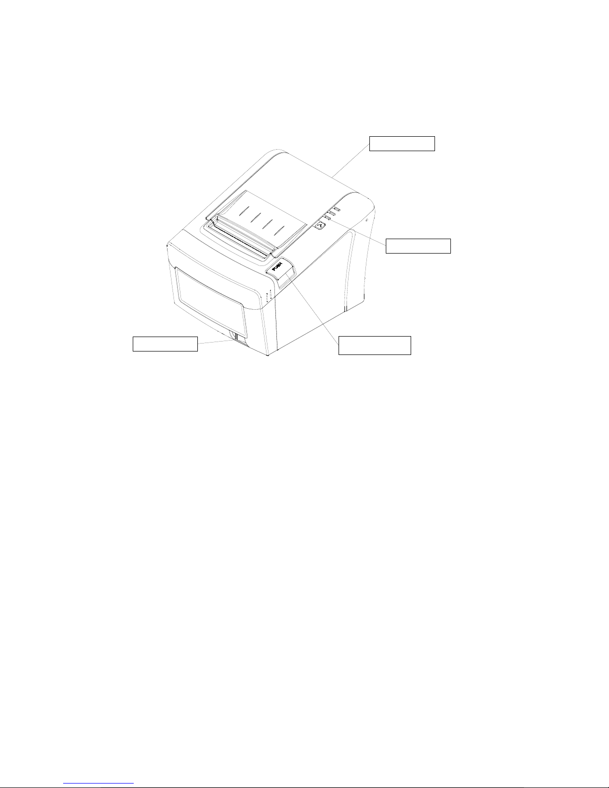
1. Parts Identifications
PRINTER COVER
Open this cover to
load or replace paper.
CONTROL PANEL
Features LED indicators
to indicate printer status
and switches to operate
the printer.
POWER SWITCH
Used to turn on/off
power to the printer.
COVER OPEN PUSH
BUTTON
Push d own th is button to
open the printer cover.
3
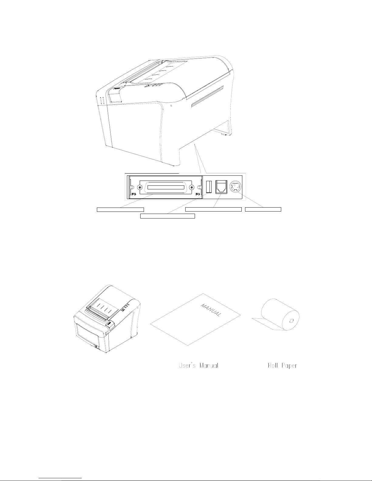
INTERFACE CONNECTOR
INTERFACE CONNEC TOR ( USB)
PERIPHERAL DRIVE CONNECTOR POWER CONNECTOR
2. Setting Up the Printer
2-1. Unpacking
Your printer box should include these items. If any items are damaged or missing, please
contact your dealer for assistance.
The Printer
4

Power Adaptor Interface Cable
2-2. Connecting the Cables
All cables connect to the connector panel on the back of the printer which is shown below:
5

INTERF ACE C O NN ECT O R
For c onn ectio n to a
host computer.
INTERFAC E CO NN ECT OR (USB)
For connection to a
host computer.
PERIPHERAL DRIVE CONNECTOR
Connects to peripheral units such
as cash drawer, etc.
Do no t co nne ct this to a tele phone .
POWER CONNECTO R
For c onnec tion o f the AC ad apte r.
Never unplug the AC ada pter while
the printer is on.
Before connecting any of the cables, make sure that both the printer and the computer are
turned off.
2-2-1. Interface Connector
6
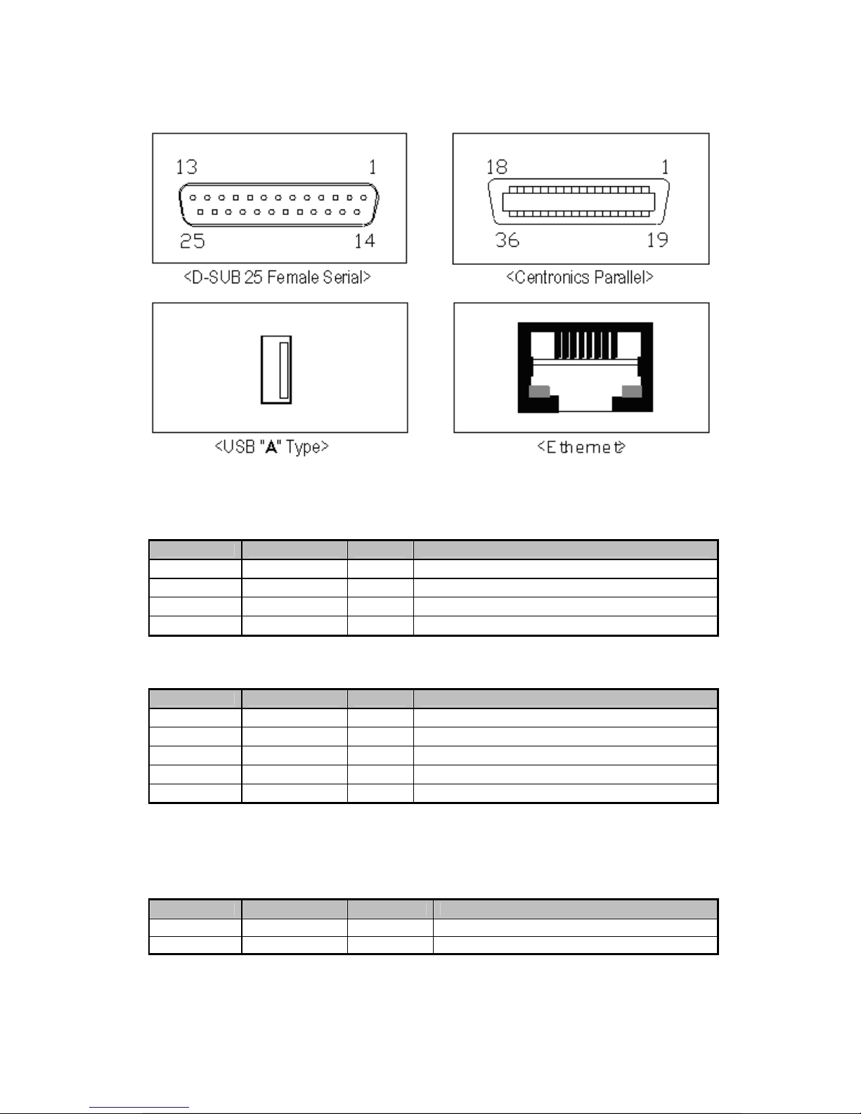
yp e
>
- USB Interface
PIN SIGNAL I/O DESCRIPTION
1 +5V - +5V
2 DATA- - Printer transmit data line
3 DATA+ - Printer transmit data line
4 GND - System Ground
- Serial Interface
PIN SIGNAL I/O DESCRIPTION
2 TxD Output Printer transmit data line RS-232C level
3 RxD Input Printer receive data line RS-232C level
4, 20 DTR Output Printer handshake to host line RS-232C level
6 DSR Input Data Send Ready
1, 7 GND - System Ground
- Centronics Parallel Interface
PIN SIGNAL I/O DESCRIPTION
1 STROBE- Input Synchronize signal Data received
2~9 DATA0~7 Input/Output Data bit Transmitted 0~7
7
 Loading...