

Page 1

EVO Laser
Barcode Scanner
User’s Guide
Page 2

Disclaimer
POS-X reserves the right to make changes in specifications and other
information contained in this document without prior notice, and the reader
should in all cases consult POS-X to determine w hethe r any such chang es hav e
been made. The information in this publication does not represent a commitment
on the part of POS-X.
POS-X shall not be liable for technical or editorial errors or omissions contained
herein; nor for incidental or consequential damages resulting from the furnishing,
performance, or use of this material.
This document contains proprietary information that is protected by copyright. All
rights are reserved. No part of this document may be photocopied, reproduced,
or translated into another language without the prior written consent of POS-X.
© 2012 All rights reserved.
Page 3

iii
Table of Contents
Introduction ............................................................................................. 1
Components ..................................................................................................... 1
Maintenance ..................................................................................................... 1
Caution and Serial Number Labels ................................................................... 2
Cable Installation and Removal ........................................................................ 3
Scanner Operation
Audible Indicators ............................................................................................. 4
Visual Indicators ............................................................................................... 5
Failure Modes ................................................................................................... 6
Typical Depth of Field ....................................................................................... 6
Troubleshooting Guide ........................................................................... 7
Design Specifications ........................................................................... 10
Configuration Introduction
Bar Code Configuration Methods ................................................................... 12
Single-Code Method.................................................................................... 12
Multi-Code Method ...................................................................................... 12
Returning to Factory Defaults ......................................................................... 13
Code Types and Decode Rules
2 of 5 Codes ................................................................................................... 14
Additional Decode Features ........................................................................... 14
Supplements .......................................................................................... 15
Scanner Operation
Redundant Scans ........................................................................................... 16
Data Transmission Delays .............................................................................. 16
Laser/Scan Modes ......................................................................................... 16
Prefixes/Suffixes
User Configurable Prefixes, All Data .............................................................. 17
Standard Prefix Characters ............................................................................ 17
Page 4

iv
Standard Suffix Characters ............................................................................ 17
User Configurable Suffixes, All Data .............................................................. 18
Code Formatting
UPC/EAN Formatting ..................................................................................... 19
Keyboard
Enable Keyboard Emulation ........................................................................... 21
Code Bytes Usage
Code Bytes 0-9 ............................................................................................... 23
Reserved Codes ............................................................................................. 24
Code Type Table ............................................................................................ 24
ASCII Reference Table................................................................................... 25
Extended Key Code Reference Table ............................................................ 29
Limited Warranty ................................................................................... 31
Page 5
1
Introduction
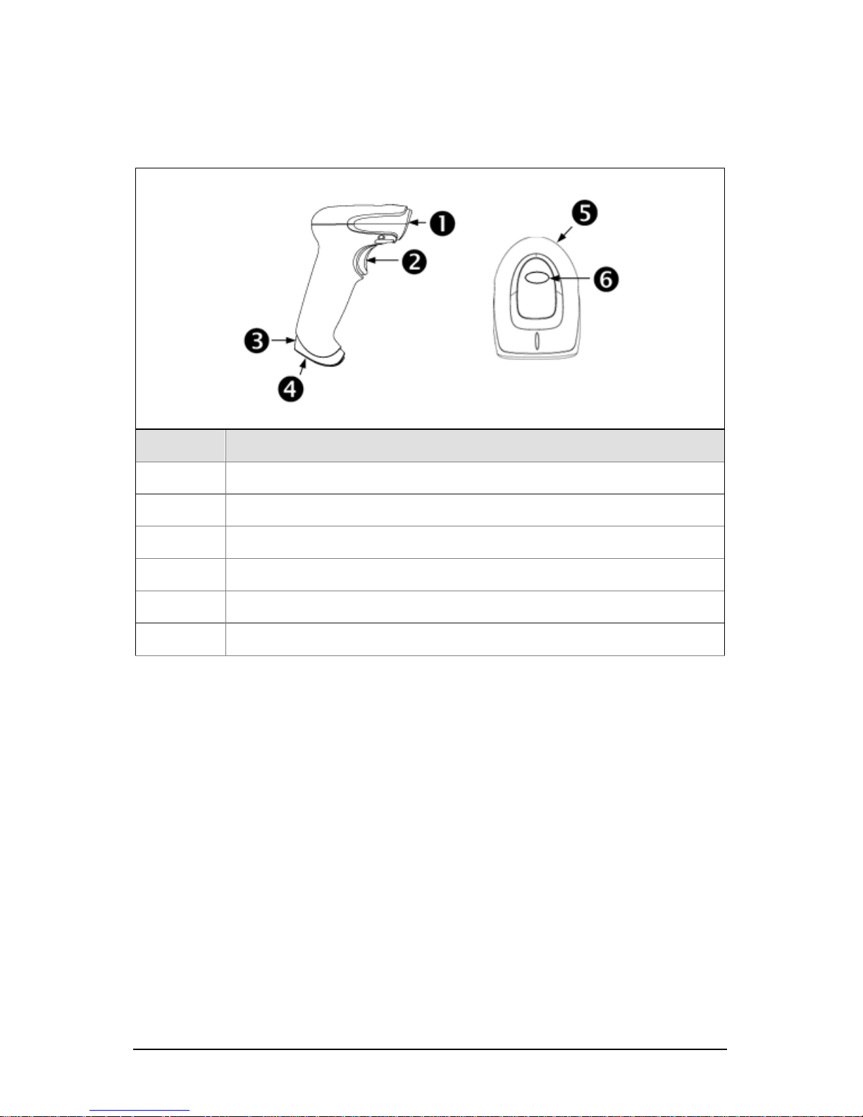
Components
Item No. Description
1 Red Output Window (Laser Aperture)
2 Trigger
3
Pinhole for Cable Release (see page 3)
4 10-Pin RJ45, Female Socket
5 Beeper Hole
6
LED Indicator (see page 5)
Figure 1. Scanner Components
Maintenance
Smudges and dirt on the unit’s window can interfere with the unit’s performance.
If the window requires cleaning, use only a mild glass cleaner containing no
ammonia. When cleaning the window, spray the cleaner onto a lint free, nonabrasive cleaning cloth then gently wipe the window clean.
If the unit’s housing requires cleaning, use a mild cleaning agent that does not
contain strong oxidizing chemi cals. Strong cleaning agents may discolor or
damage the unit’s exterior.
Page 6
2
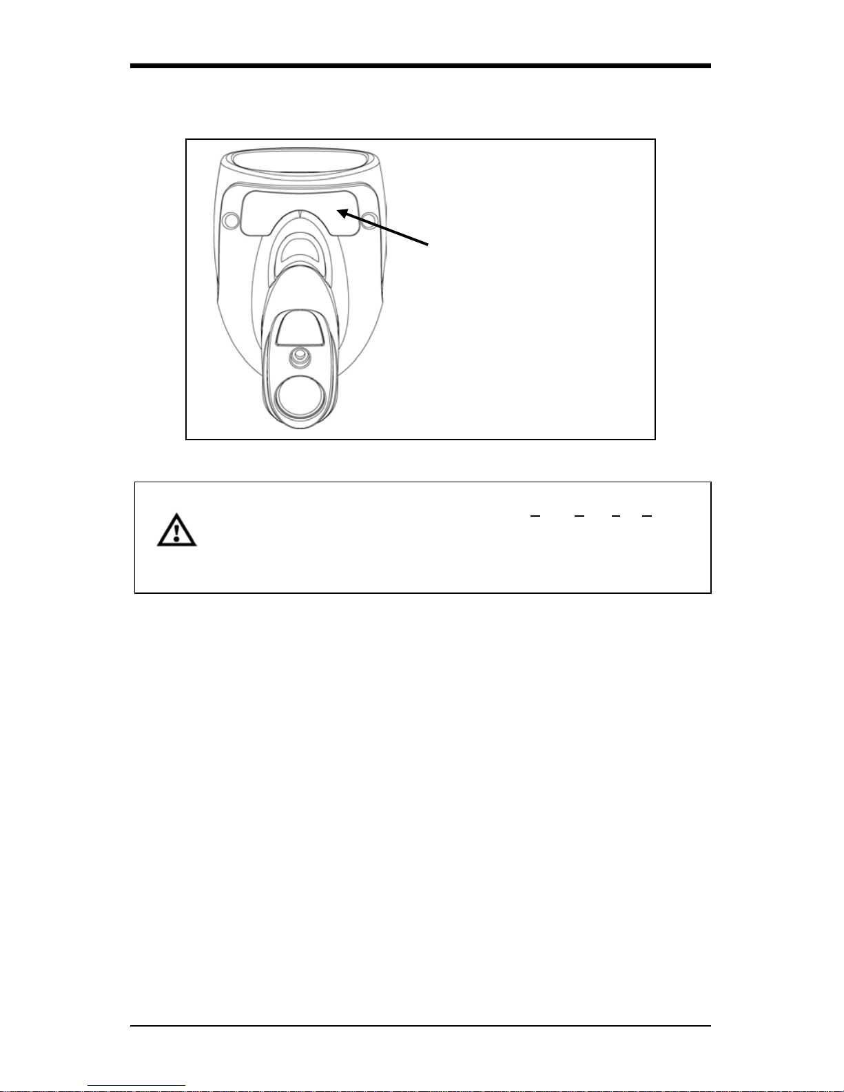
Caution and Serial Number Labels
Figure 2. Label Location on the Bottom of the Scanner
Caution: To maintain compliance with applicable standards, all circuits connected to
the imager must meet the requirements for SELV (Safety Extra Low Voltage)
according to EN/IEC 60950-1.
To maintain compliance with standard CSA C22.2 No. 60950-1/UL 60950-1
and norm EN/IEC 60950-1, the power source should meet applicable
performance requirements for a limited power source.
Item N umber,
Serial Number and
Compliance Information
location.
Page 7
3
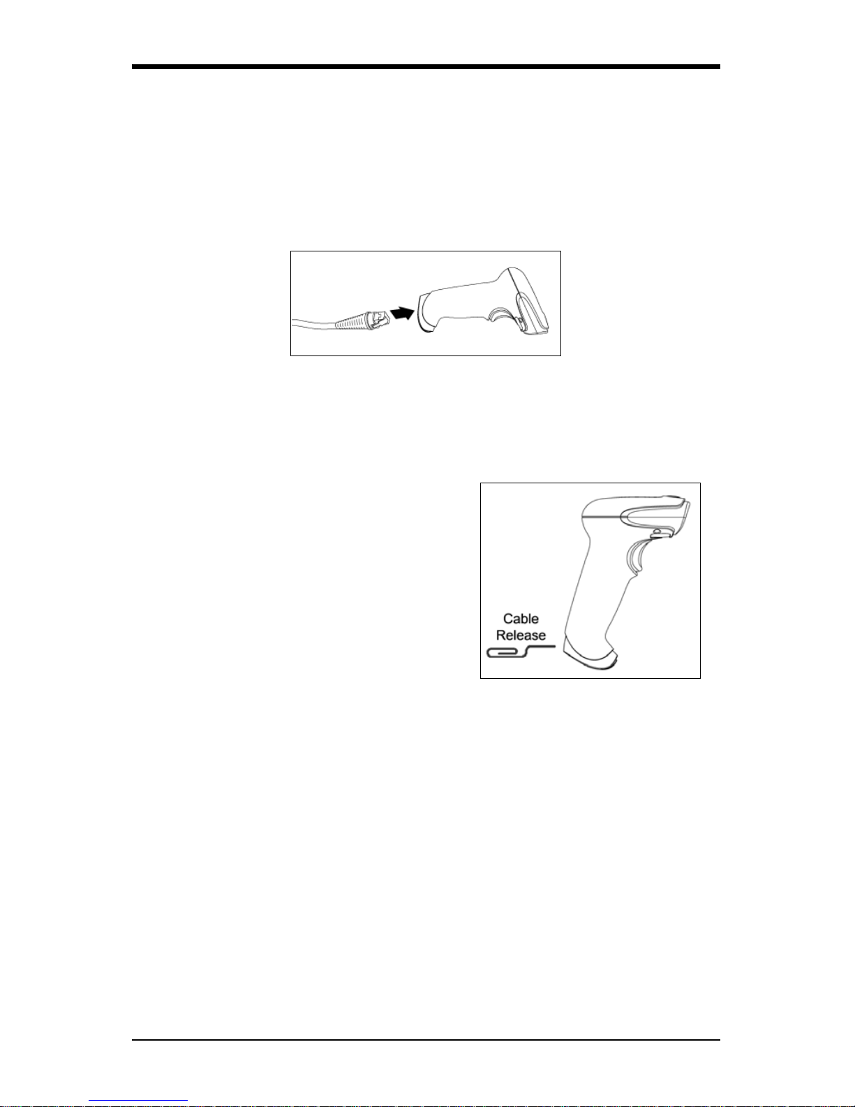
Cable Installation and Removal
Installation
1. Insert the cable’s modular connect or into the socket on the scanner.
2. Pull gently on the cable strain relief to ensure the cable is installed.
Figure 3.
Removal
Turn off power to the host system before removing the cable from the scanner.
1. Locate the small pinhole on the
front side of the scanner near the
end of the handle.
2. Bend an ordinary paper clip into the
shape shown.
3. Insert the paper clip (or other small
metallic pin) into the small pinhole.
There will be a faint ‘click’ when the
connector’s lock releases.
4. Pull gently on the cable’s strain
relief to remove the cable.
Figure 4.
Page 8

4
Scanner Operation
Audible Indicators
When the scanner is operational, the scanner provides audible feedback to
indicate the status of the scanner and the last scan. Eight settings are available
for the tone of the beep (normal, six alternate tones and no tone).
One Beep – On Power Up
When the unit powers up, the green LED turns on, then the red LED flashes and
the scanner beeps once. The red LED will remain on for the duration of the
beep. The scanner is now ready to scan.
One Beep – During Operation
When the scanner successfully reads a bar code, the red LED will flash and the
scanner beeps once (if programme d to do so). If the scanner does not beep
once and the red light does not flash, then the bar code has not been
successfully read.
Three Beeps – During Operation
When entering the configuration mode, the red LED flashes while the scanner
simultaneously beeps three times. The red LED continues to flas h until the unit
exits configuration mode. Upon exiting configuration mode, the scanner beeps
three times and the red LED stops flashing.
When configured for communication timeout, three beeps during operat ion
indicates that a communication timeout has occurred.
Page 9
5
Visual Indicators
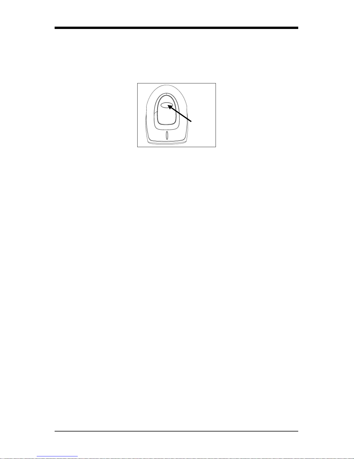
The scanner is equipped with a red LED and green LED, which indicate the
scanner’s state and the status of the curr ent scan respectively when the unit is in
operation.
Figure 5. LED Location
Green and Red LEDs Are Off
The LEDs will not be illuminated if the scanner is not receiving power from the
host or transformer.
Steady Green
Steady green indicates normal pulse or continuous laser operation.
Accompanied by a razzberry tone, a steady green LED indicates that an invalid
bar code has been scanned.
Steady Green and Single Red Flash
When the scanner successfully reads a bar code, the red LED will flash and the
scanner will beep. If the red LED does not flash and the scanner does not beep,
the bar code has not been successfully read.
Steady Green and Steady Red
After a successful read, the scanner transmits the data to the host device. Some
communication modes require that the host inform the scanner when data is
ready to be received. If the host is not ready to accept the information, the
scanner’s red LED will remain on until the data can be transmitted.
Steady Green and Continuous Flashing Red
When entering the configuration mode, the red LED will flash, the green LED will
turn on and the scanner will beep three times. The red LED will continue to flash
and the green LED will stay on until the unit exits the configuration mode.
LED
Page 10
6
Failure Modes
One Razzberry Tone – On Power Up
This indicates the scanner has experienced a laser or subsystem failure. Return
the unit for repair to an Authorized Service Center.
Continuous Razzberry Tone with no LEDs
If, upon power up, the scanner emits a continuous razzberry tone, then the
scanner has an experienced an electronic failure. Return the unit for repair to an
Authorized Service Center.
Three Beeps – On Power Up
If the scanner beeps three times on power up, then the non-volatile memory
(NovRAM) that holds the scanner configuration has failed. You must return the
unit for repair to an Authorized Service Center.
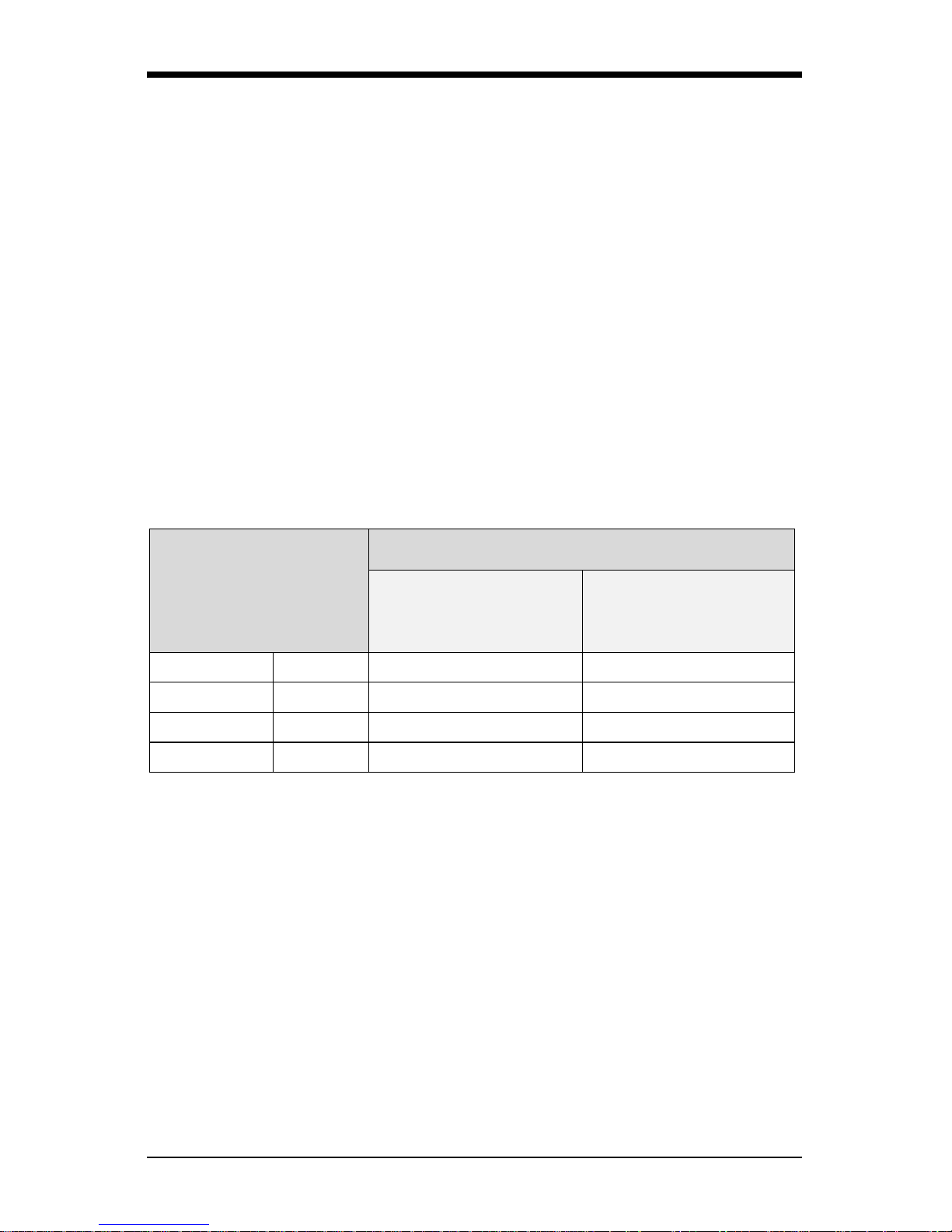
Typical Depth of Field by Bar Code Element Width
Bar Code Element
Width
Depth of Field
Start
(From Scanner Face)
End
(From Scanner Face)
0.13 mm 5.2 mil 76 mm (3") 127 mm (5")
0.19mm 7.5 mil 51 mm (2") 203 mm (8")
0.26 mm 10.4 mil 25 mm (1") 229 mm (9")
0.33 mm 13 mil 13 mm (0.5") 254 mm (10")
Page 11

7
Troubleshooting Guide
The following guide is for reference purposes only. Contact a customer service
representative to preserve the limited warranty terms.
Symptoms Possible Causes Solution
All Interfaces
The unit has no
LEDs, beep or laser.
No power is being
supplied to the
unit.
Check the transformer, the out let
and power strip. Mak e sure the
cable is plugged into the unit.
No power is being
supplied to the unit
from host.
Some host systems cannot supply
enough current to power the
scanner. A power supply may be
needed.
At power up the
unit beeps two
times and
alternately flashes
the LEDs.
There is a ROM
failure.
A flash ROM upgrade is required.
At power up the unit
beeps three times.
There is a nonvolatile RAM
failure.
Contact a customer service
representative.
At power up there
is a continuous
razz tone.
There has been a
diagnostic failure.
At power up there
is a razz tone and
the green LED
flashes.
There is a VLD
failure.
At power up there
is a razz tone and
both LEDs flash.
There is a
scanning
mechanism
failure.
The unit scans,
communicates and
beeps twice.
The same symbol
timeout is set too
short.
Adjust the same symbol timeout
for a longer time.
The unit powers up,
but does not beep.
The beeper may
be disabled or no
tone has been
selected.
Enable beeper and select a tone.
Page 12

8
Symptoms Possible Causes Solution
The unit powers
up, but does not
scan and/or
beep.
The unit is trying to
scan a particular
symbology that is not
enabled.
UPC/EAN, Code 39, interleaved 2
of 5, Code 93, Code 128 and
Codabar are enabled by default.
Verify the type of bar code being
read has been selected.
The unit powers
up, but does not
scan and/or
beep.
The bar code being
scanned does not
satisfy the configured
criteria for character
length lock or
minimum length.
Verify the bar code being scanned
falls into the configured criteria.
The scanner defaults to a
minimum of three-character bar
code.
Serial Emulation USB Interfaces
The unit scans a
bar code, but
locks up after the
first scan and the
red LED stays
on.
The unit is configured
to support some form
of host handshaking
but is not receiving
the signal.
If the unit is setup to support
ACK/NAK, RTS/CTS, XON/XOFF
or D/E, verify that the host cable
and host are supporting the
handshaking properly.
The unit scans,
but the data
tran
smitted to the
host is incorre ct .
The unit’s data format
does not match the
host system’ s
requirements.
Verify the unit’s data format
matches that required by the host.
Make sure that the unit is
connected to the proper host port.
The unit beeps
at some bar
codes but NOT
for others of the
same bar code
symbology.
The bar code may
have been printed
incorrectly.
Check if it is a check
digit/character/or border problem.
The unit is not
configured correctly
for the type of bar
code being scanned.
The minimum symbol
length setting does
not work with the bar
code.
Check if the corre ct min i mu m
symbol length is set.
Keyboard Wedge Interface
The unit scans
the bar code but
there is no data.
The unit’s
configuration is not
correct.
Make sure the scanner is
configured for the appropriate
mode.
Page 13

9
Symptoms Possible Causes Solution
The unit scans
but the data is
not correct.
The unit’s
configuration is not
correct.
Make sure that the proper PC type
AT, PS2 or XT is selected. Verify
the correct country code and data
format is selected. Adjust the
inter-character delay symptom.
The unit is
transmitting
each character
twice.
The unit’s
configuration is not
correct.
Increase the interscan code delay
setting. Adjust whether the F0
break is transmitted.
It may be necessary to try this in
both settings.
Alpha
characters show
as lower case.
The computer is in
Caps Lock mode.
Enable the Caps Lock detect
feature of the scanner to detect
whether the PC is operating in
Caps Lock.
Everything
works except for
a couple of
characters.
These characters
may not be supported
by that country’s key
look up table.
Try operating the scanner in Alt
mode.
Page 14
10
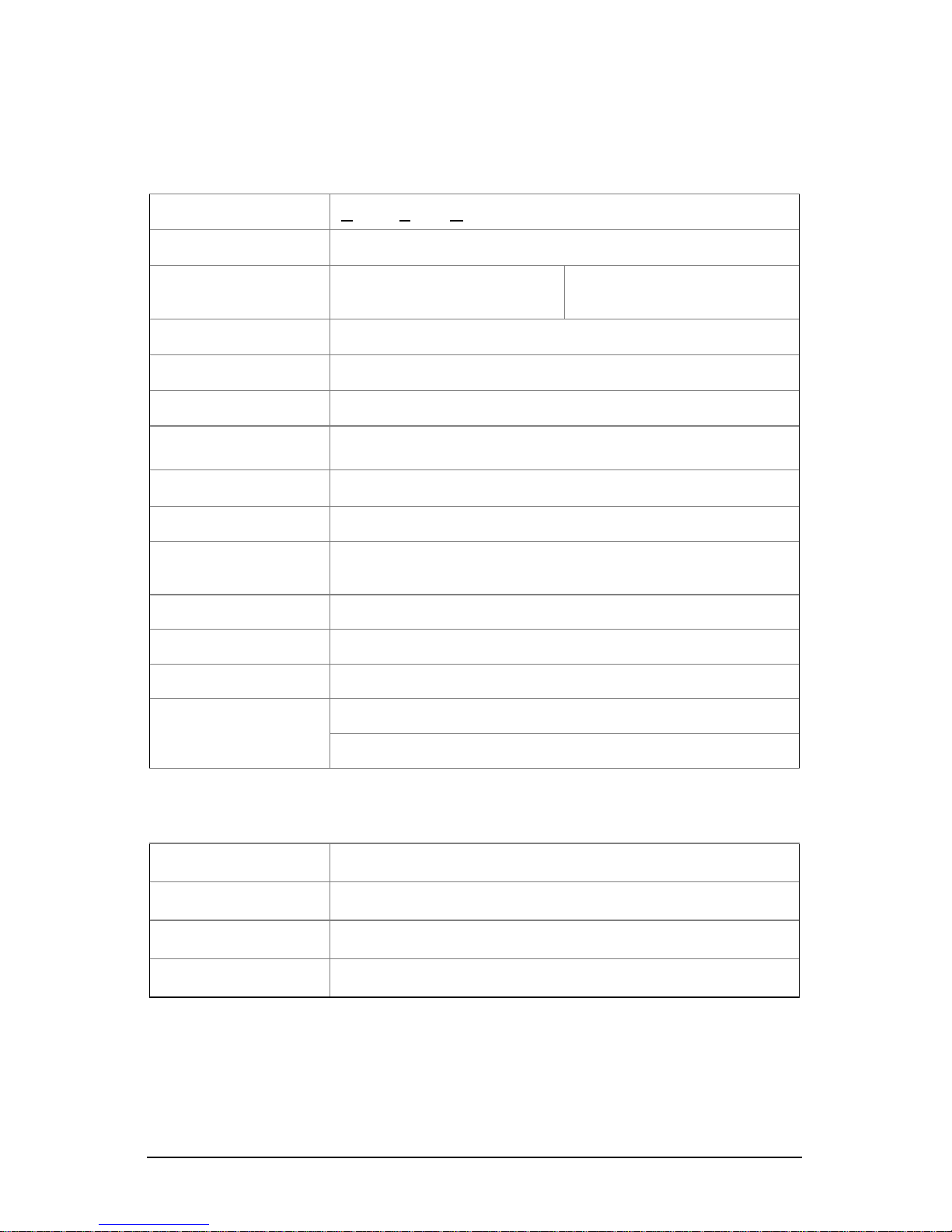
Design Speci f ications
Operational
Light Source:
Visible Laser Diode (VLD) @ 650 nm
Laser Power: Less than 1.0 mW average
Depth of Scan Field:
12.7 mm – 254 mm
(0.5" – 10")
0.33 mm (13 mil) Bar Code
Scan Speed: 72 ± 2 scan lines per second
Scan Pattern: Single scan line
Minimum Bar Width: 0.1016 mm (4 mil)
Decode Capability: Reads standard 1D and GS1 DataBar symbologies.
System Interfaces: USB, Keyboard Wedge
Print Contrast: 35% minimum reflectance difference
No. Characters Read:
Up to 80 data characters. The max imum number will
vary based on symbology and density.
Scan Angle: 46° Horizontal
Pitch, Yaw: 68°, 52°
Beeper Operation: 7 tones or no beep
Indicators (LED):
Red = good read
Green = laser on, ready to scan
Mechanical
Length: 110 mm (4.3")
Width: 70 mm (2.8")
Height: 153 mm (6.0")
Weight: 120 g (4.23 oz)
Specifications subject to change without notice.
Page 15

11
Electrical
Input Voltage: 5VDC ± 0.25V
Operating Power: Standby: 700 mW
Decoding USB: 975 mW
Decoding KBW: 875 mW
Operating Current: Standby: 140 mA average @ 5VDC
Decoding USB: 195 mA average @ 5VDC
Decoding KBW: 175 mA average @ 5VDC
DC Transformers: Class II; 5.2VDC @ 1A
Environmental
Temperature:
Operating: 0°C to 40°C (32°F to 104°F)
Storage: -40°C to 60°C (-40°F to 140°F)
Humidity: 5% to 95% relative humidity, non-condensing
Light Levels: Up to 4842 Lux (450 footcandles)
Shock: Designed to withstand 1.0 m (3.3 ft.) drops
Contaminants: Sealed to resist airborne particulate contaminants
Ventilation: None required
Specifications subject to change without notice.
Page 16

12
Configuration Introduction
Your new scanner has been factory configured with a set of default parameters.
Since many host systems have unique formats and protocol requirements, a
wide range of configurable features that may be selected using this bar code
based configuration tool are provided. Once the configuration is completed, t he
scanner stores the settings in nonvolatile memory (NOVRAM). NOVRAM saves
the settings when the power is off.
Note: Bar code descriptions marked with an asterisk ( * ) define a feature that is
a factory default. Bar codes marked with a tilde ( ~ ) require the
Multi-Code configuration method.
Bar Code Configuration Methods
Scanners can be bar code configured in two ways:
the Single-Code Method and the Multi-Code Method.
Single-Code Method
Most features can be enabled or disabled using the Single-Code Method.
1. Power up the scanner.
2. Scan the bar code for the desired feature.
3. The scanner will emit a multi-toned beep to indicate the configuration
has been saved to NOVRAM.
Multi-Code Method
All features can be enabled or disabled using the Multi-Code Method.
A feature marked with a tilde ( ~ ) requires the Multi-Code Method.
1. Power up the scanner.
2. Scan the Enter/Exit Configuration Mode bar code (3 beeps).
3. Scan the bar code for the desired feature (1 beep). Multiple feature s can
be enabled/disabled before scanning the enter/exit configuration mode
bar code.
4. Scan the Enter/Exit Configuration Mode bar code (3 beeps) and save
the new configuration. To abort a configuration change, power off the
scanner before scanning the Enter/Exit code.
Enter/Exit Configuration Mode
³ 9 9 9 9 9 9
Page 17

13
Returning to Factory Defaults
Scan the Recall Defaults bar code to erase all previous settings and return
the scanner to its factory default communication protocol.
Recall Defaults
³ 9 9 9 9 9 8
Page 18
14
Code Types and Decode Rules
Bar code descriptions marked with an asterisk ( * ) define a feature that is a
factory default. Bar codes marked with a tilde ( ~ ) require the Multi-Code
configuration method.
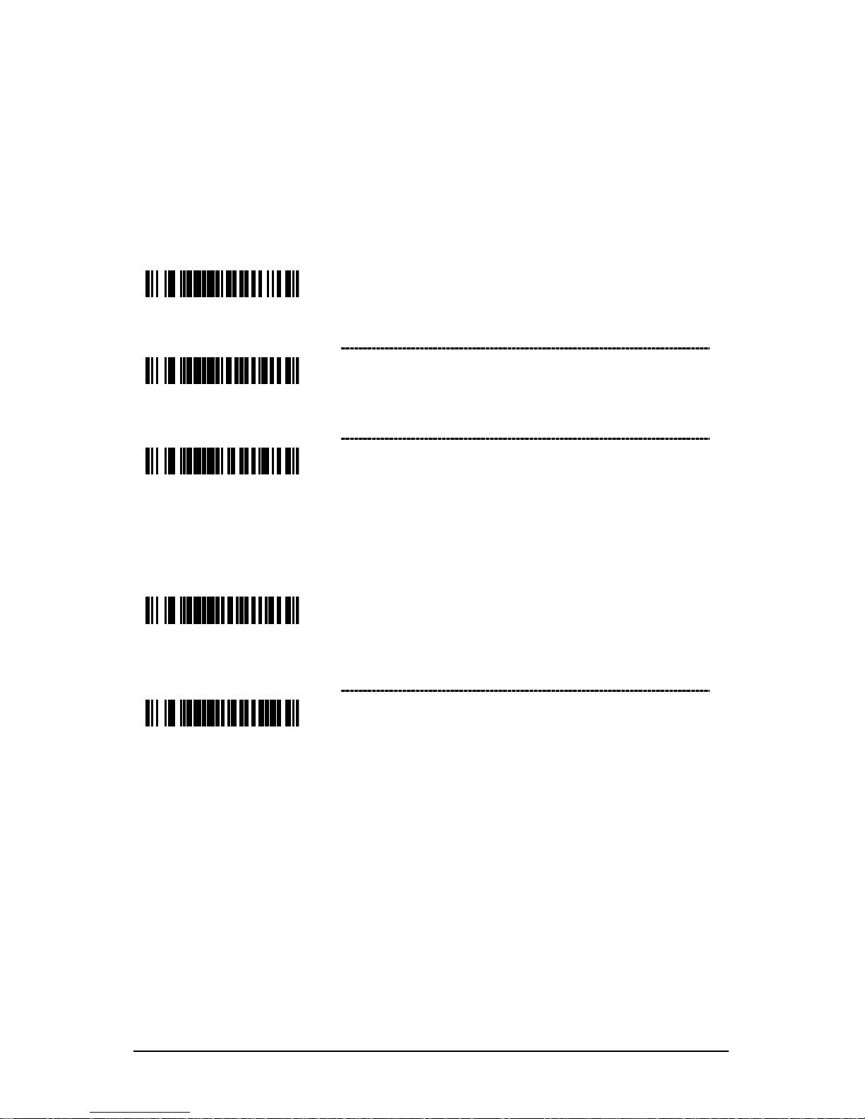
2 of 5 Codes
³ 9 0 1 6
0 0
~ ITF Symbol Length Lock 1 – To specify a first
ITF symbol length lock, scan this bar code and
the appropriate code byte sequence located
on page
23.
³ 9 0
1 7 0 0
~ ITF Symbol Length Lock 2 – To specify a second
ITF symbol length lock, scan this bar code and the
appropriate code byte sequence located
on page 23.
³ 9
0
3 4 0
0
~ ITF Minimum Symbol Length – To specify a
minimum number of ITF characters to be decoded,
scan the appropriate code byte sequence located
on page 23.
Additional Decode Features
³ 9 0 1 8 0 0
~ Minimum Symbol Length – Single-line default
is 3.
Combine this code with the proper code bytes
(on page 23), to specify the minimum number
of characters in all non-UPC/EAN bar codes.
³ 9
0 1 9 0 0
~ Symbol Length Lock – Combine this code with
the proper code bytes, to lock the bar code’s
length into place.
Page 19
15
Supplements
³
1 2
5
1 1
4
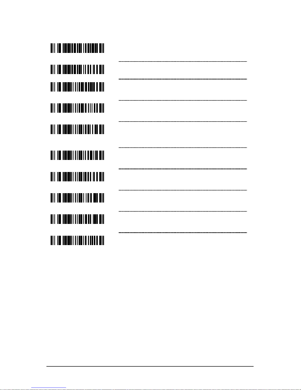
Enable Bookland (979) Supplement Required
³
1
2 5 1
0 4
* Disable Bookland (979) Supplement Required
³ 1 0 1 4 1 7
Enable Bookland (978) Supplement Required
³
1 0 1 4 0 7
* Disable Bookland (978) Supplement Required
³ 1 0 1 3 1 4
Enable 977 (2 Digit) Supplement Required –
The scanner will require a 2 digit supplement to be
scanned when an EAN-13 code begins with 977.
³ 1 0 1 3 0
4
* Disable 977 (2 Digit) Supplement Required
³
1 0 1
3 1 5
Enable ISBN Check Digit Transmission
³ 1 0 1 3 0 5
Disable ISBN Check Digit Transmission
³ 1 0 1 3 1 7
Enable Bookland to ISBN Conversion
³ 1
0 1 3 0 7
* Disable Bookland to ISBN Conversion
Page 20
16
Scanner Operation
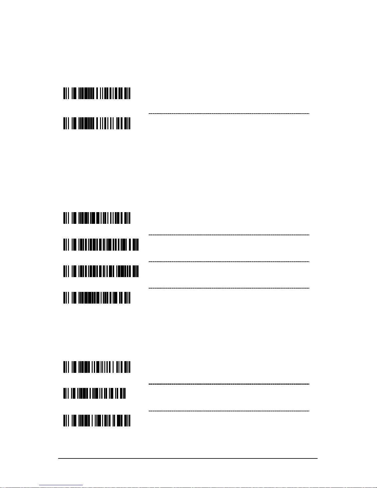
Redundant Scans
³ 3 0 1 1 0 0
* 0 Redundant Scans – Requires 1 good decode
for a good scan.
³ 3 0 1
1 1 0
1 Redundant Scan – Requir e s 2 consecut iv e
decodes of the same bar code data for a good
scan.
Data Transmission Delays
Use these codes to select the amount of delay between sending data characters
from the scanner to the host. This helps prev ent the scanner f r om overf low ing
host-input buffers.
³ 8 1
8 8 1 0
* 1 msec Intercharacter Delay
³ 8 1 8 8 1 0 0
10 msec Intercharacter Delay
³ 8 1 8 8 2 5 0
25 msec Intercharacter Delay
³ 9 1
8 8 0 0
~ Variable msec Intercharacter Delay – Scan this
bar code and a sequence of code bytes on page
23 t
o set the delay between charact ers sent to the
host system (range from 1 to 255 msecs.).
Laser/Scan Modes
³ 1 1 8 7 0
3
Enable Automatic Scanning
³ 4 1 8 3 3 4
Continuous Blinky Scan – The laser blinks
continuously and the IR is inactive.
³ 4 1 8 3 5 4
Enable Manual Trigger – The laser activates
when the CodeGate button is pressed.
Page 21
17
Prefixes/Suffixes
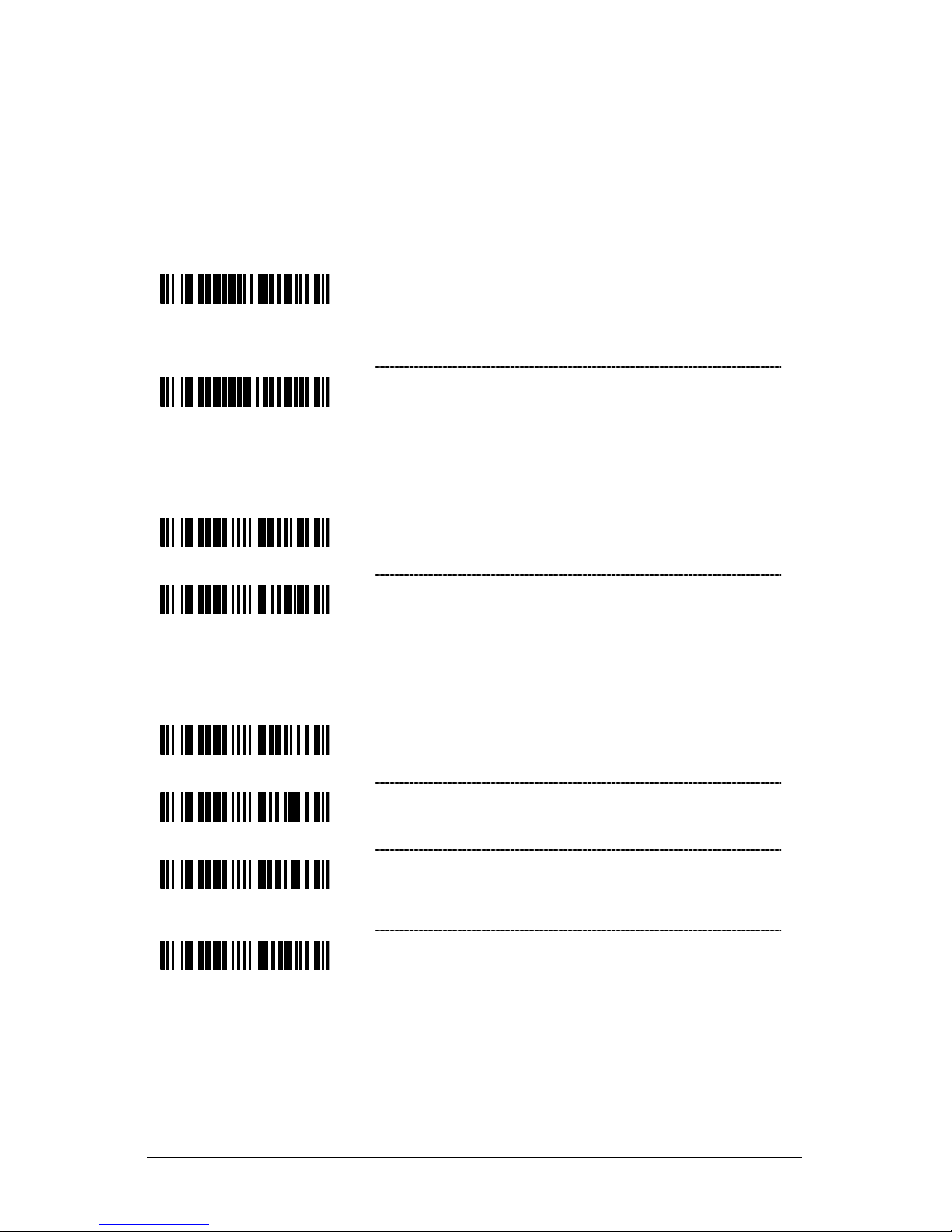
Scan the Enter Configuration Mode bar code before trying to set these features
(see the Multi-Code Method on page 12.)
User Configurable Prefixes, All Data
³ 9 0 3 5 0 0
~ Configurable Prefix Character #1 – A prefix ID
can be added and assigned for data transmission.
Use this code with a code byte sequence, on page
23, which represents the desired character.
³ 9 0 3 6 0 0
~ Configurable Prefix Character #2 – Assigns a
second configurable prefix character.
Standard Prefix Characters
³ 1 1 6
6 1 5
Enable STX Prefix – The scanner will transmit a
Start of TeXt (ASCII 02H) before each bar code.
³ 1
1 6 6
0 5
* Disable STX Prefix
Standard Suffix Characters
³
1
1 6 6
1 3
* Enable CR Suffix – The scanner transmits a
carriage return after each bar code.
³ 1 1
6 6 0 3
Disable CR Suffix
³
1 1 6 6 1 2
* Enable LF Suffix – The scanner transmits a line
feed after each bar code. Disabled when
keyboard wedge defaults are loaded.
³
1 1 6 6 0 2
Disable LF Suffix
Page 22
18
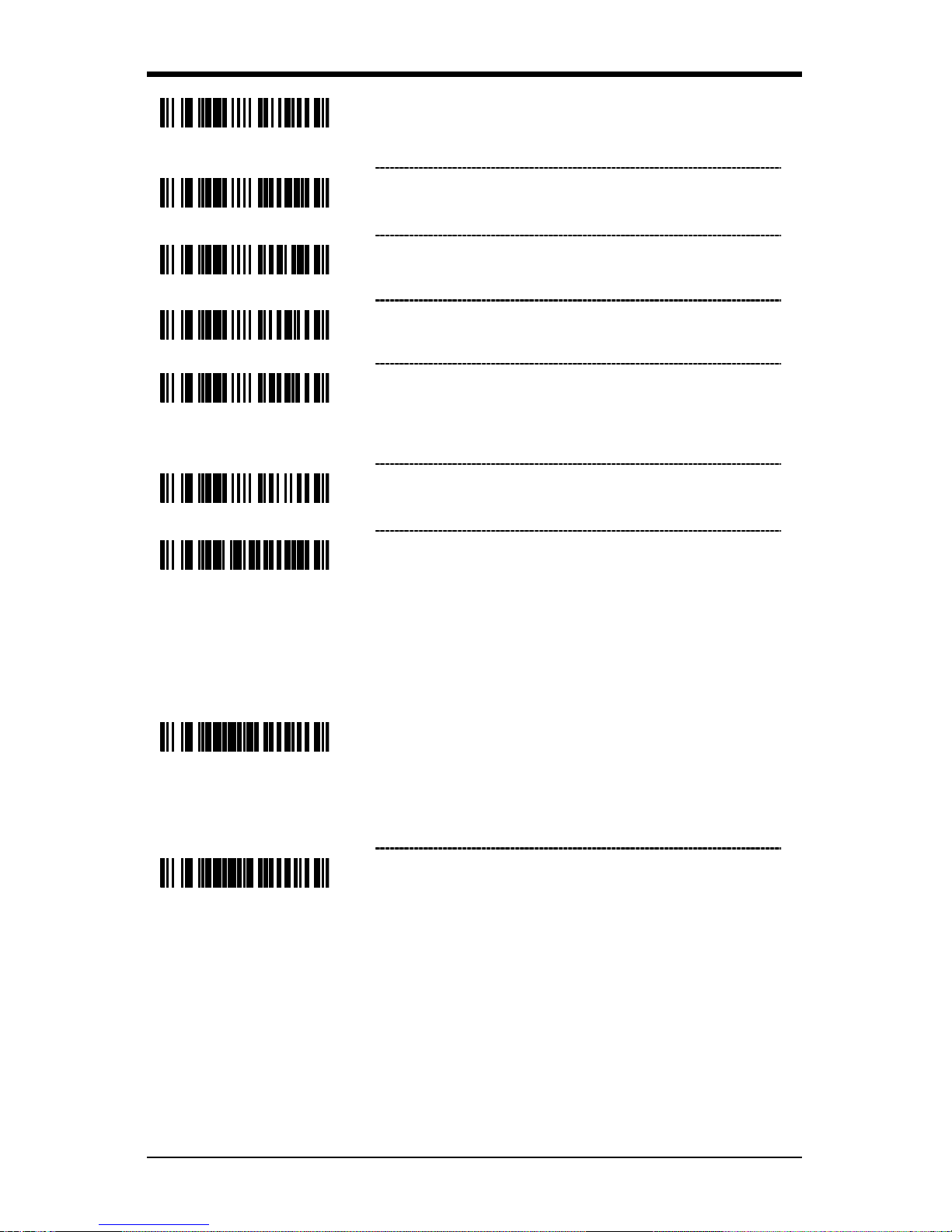
³ 1 1 6 6 1 0
Enable Tab Suffix – The scanner will transmit a
TAB (ASCII 09H) after each bar code.
³ 1 1
6 6 0
0
* Disable Tab Suffix
³ 1
1
6 6 1
4
Enable ETX Suffix – The scanner will transmit
End of TeXt (ASCII 03H) after the bar code date.
³ 1
1 6 6 0 4
* Disable ETX Suffix
³ 1 1 6 6 1 6
Enable UPC Suffix ID – The scanner will
transmit a suffix after any UPC/EAN bar code.
The suffixes are A (UPC-A), E (UPC-E),
F (EAN-13) and F (EAN-8).
³
1 1 6 6
0 6
* Disable UPC Suffix ID
³ 9 4 1 6 0 0
Enable NCR Suffix Character
User Configurable Suffixes, All Data
Note: Scan the Enter/Exit Configuration mode code before trying to set this
feature. Refer to Multi-Code Method on page 12.
³
9 0 4 5 0 0
~ Configurable Suffix Character #1 – A suffix ID
can be added and assigned for data
transmission. Use this code with a 3 code byte
sequence, on page
23, which represents the
desired character.
³ 9 0 4 6 0 0
~ Configurable Suffix Character #2 – Assigns a
second configurable suffix character.
Page 23
19
Code Formatting
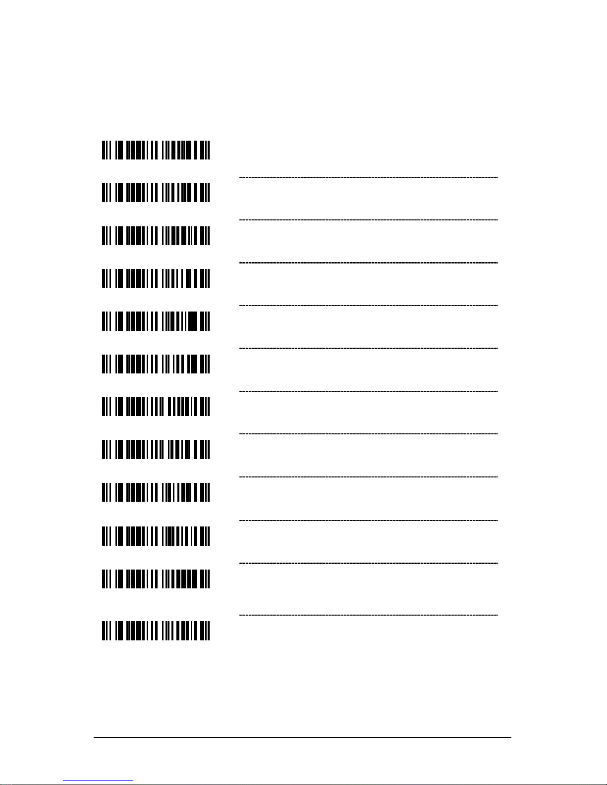
UPC/EAN Formatting
³ 1 0 7 5 1 7
* Transmit UPC-A Check Digit
³ 1 0 7 5 0
7
Do Not Transmit UPC-A Check Digit
³ 1 0 7 5 1 6
Transmit UPC-E Check Digit
³
1 0 7 5 0 6
* Do Not Transmit UPC-E Check Digit
³ 1 0
7 5 1 5
Expand UPC-E to 12 Digits – Expand UPC-E bar
codes to the 12 digit equivalent, UPC-
A bar codes.
³ 1
0 7 5
0 5
* Do Not Expand UPC-E to 12 Digits
³ 1 0 7 6 0 2
* Send Number System on Expanded UPC E
³ 1 0
7 6 1 2
Do Not Send Number System on Expanded
UPC E
³ 1
0 7 5 1 0
Enable GTIN Formatting
³ 1 0 7
5 0 0
* Disable GTIN Formatting
³ 1 0
7 5 1 4
Convert UPC-A to EAN-13 – The scanner
converts UPC-A to EAN-13 by transmitting a
leading zero before the bar code.
³ 1
0 7 5 0 4
* Do Not Convert UPC-A to EAN-13
Page 24

20
³ 1 0 7 5 1 3
Transmit Lead Zero on UPC-E – This option will
transmit a zero before each UPC-E bar code.
³ 1
0 7 5
0 3
Do Not Transmit Lead Zero on UPC-E
³ 1 0
7 5 1
2
Convert EAN-8 to EAN-13 – The scanner will
transmit five zeros before the bar code to convert
EAN-8 to EAN-13.
³ 1 0 7 5 0 2
* Do Not Convert EAN-8 to EAN-13
Page 25

21
Keyboard
Enable Keyboard Emulation
³ 9 9 9 9 9 4
Load Keyboard Wedge Defaults – Loads the
default settings for keyboard wedge mode.
³ 5 1 5 5 1 4 3
* Enable Keyboard Wedge Emulation – Use this
with an external keyboard. Transmit in wedge
made to allow standard PC keyboards to
communicate when no bar code data is available.
Page 26

22
ASCII (HEX) ASCII Control Extended Key
00H Null Numeric Keypad + (Plus)
01H SOH Num Lock
02H STX Down Arrow
03H ETX Numeric Keypad - (Minus)
04H EOT Insert
05h ENQ Delete
06H ACK System Request
07H BEL (Right Arrow)
08H BS (Left Arrow)
09H TAB Tab
0AH LF Caps Lock
0BH VT Shift Tab
0CH FF Left Alt
0DH CR Enter
0EH SO Left Control
OFH SI Up Arrow
10H DLE F1
11H DC1 F2
12H DC2 F3
13H DC3 F4
14H DC4 F5
15H NAK F6
16H SYN F7
17H ETB F8
18H CAN F9
19H EM F10
1AH SUB Home
1BH ESC Esc
1CH FS Page Up
1DH GS Page Down
1EH RS Print Screen
1FH US End
Page 27

23
Code Bytes Usage
The scanner must be in Configuration Mode for the features requiring code bytes
for configuration. The Enter/Exit Configuration Mode bar code must be scanned
before starting the configuration cycle. User configurable prefix/suffix characters
can then be saved by scanning the 3 digit decimal equivalent of the ASCII
character into the appropriate character location with the code byte bar codes.
Example: To add an asterisk (*) as a P refix, scan the ba r codes.
1. Enter/Exit Configuration Mode (3 beeps)
2. Configurable Prefix #1 (1 beep)
3. Code Byte 0 (1 beep)
4. Code Byte 4 (2 beeps)
5. Code Byte 2 (3 beeps)
6. Enter/Exit Configuration Mode (3 beeps)
Code Bytes 0–9
³ 0
Code Byte 0
³ 1
Code Byte 1
³ 2
Code Byte 2
³ 3
Code Byte 3
³ 4
Code Byte 4
³ 5
Code Byte 5
³ 6
Code Byte 6
³ 7
Code Byte 7
Page 28
24
³ 8
Code Byte 8
³ 9
Code Byte 9
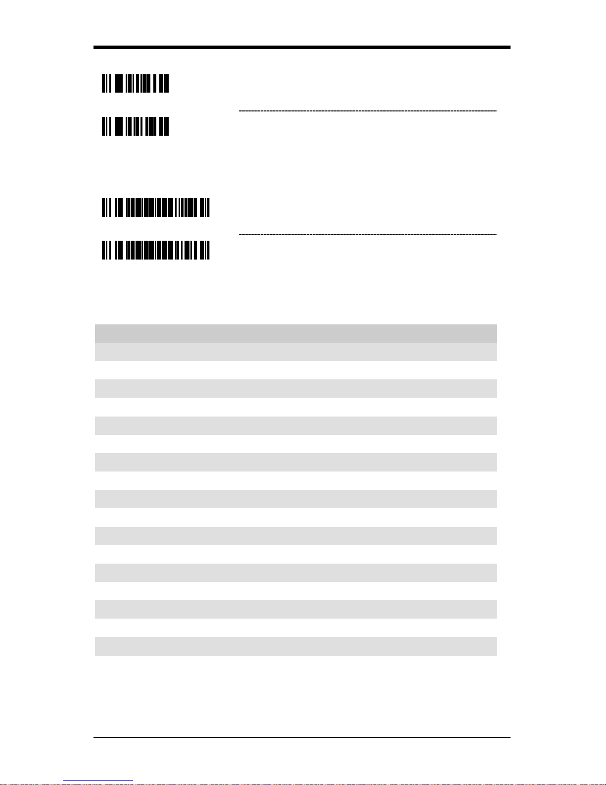
Reserved Codes
³ 9 9 9 9 8 8
~ Enable Reserved Code
³ 9 9 9 9 8 7
~ Disable Reserved Code
Code Type Table
Code Byte Code Types
004 UPC-A
002 UPC-E
003 EAN-8
005 EAN-13
080 Code 39
081 Codabar
082 Interleaved 2 of 5
083 Code 128
084 Code 93
091 MSI Plessey
092 Code 11
093 Airline 2 of 5 (15 digits)
094 Matrix 2 of 5
095 Telepen
096 UK Plessey
099 TRI-OPTIC
098 Standard 2 of 5
097 Airline (13 digits)
Page 29

25
ASCII Reference Table
HEX Value
Decimal Value/
Code Byte Value
Character
Control
Keyboard Eqv
00 000 NUL @
01 001 SOH A
02 002 STX B
03 003 ETX C
04 004 EOT D
05 005 ENQ E
06 006 ACK F
07 007 BEL G
08 008 BS H
09 009 HT I
0A 010 LF J
0B 011 VT K
0C 012 FF L
0D 013 CR M
0E 014 SO N
0F 015 SI 0
10 016 DLE P
11 017 DC1 Q
12 018 DC2 R
13 019 DC3 S
14 020 DC4 T
15 021 NAK U
16 022 SYN V
17 023 ETB W
18 024 CAN X
19 025 EM Y
1A 026 SUB Z
1B 027 ESC [
1C 028 FS \
Page 30

26
HEX Value
Decimal Value/
Code Byte Value
Character
Control
Keyboard Eqv
1D 029 GS ^
1E 030 RS _
1F 031 US space,blank
20 032 SP
21 033 !
22 034 “
23 035 #
24 036 $
25 037 %
26 038 &
27 039 ‘ apostrophe
28 040 (
29 041 )
2A 042 *
2B 043 +
2C 044 , comma
2D 045 - minus
2E 046 . period
2F 047 /
30 048 0 number zero
31 049 1 number one
32 050 2
33 051 3
34 052 4
35 053 5
36 054 6
37 055 7
38 056 8
39 057 9
3A 058 :
3B 059 ;
Page 31

27
HEX Value
Decimal Value/
Code Byte Value
Character
Control Keyboard
Eqv
3C 060 < less than
3D 061 =
3E 062 > greater than
3F 063 ?
40 064 @ shift P
41 065 A
42 066 B
43 067 C
44 068 D
45 069 E
46 070 F
47 071 G
48 072 H
49 073 I letter l
4A 074 J
4B 075 K
4C 076 L
4D 077 M
4E 078 N
4F 079 O letter O
50 080 P
51 081 Q
52 082 R
53 083 S
54 084 T
55 085 U
56 086 V
57 087 W
58 088 X
59 089 Y
Page 32

28
HEX Value
Decimal Value/
Code Byte Value
Character
Control Keyboard
Eqv
5A 090 Z
5B 091 [ shift K
5C 092 \ shift L
5D 093 ] shift M
5E 094 ^ à,shift N
5F 095 _
♣
, shift 0, underscore
60 096 ‘ accent grave
61 097 a
62 098 b
63 099 c
64 100 d
65 101 e
66 102 f
67 103 g
68 104 h
69 105 I
6A 106 j
6B 107 k
6C 108 l
6D 109 m
6E 110 n
6F 111 o
70 112 p
71 113 q
72 114 r
73 115 s
74 116 t
75 117 u
76 118 v
77 119 w
78 120 x
Page 33

29
HEX Value
Decimal Value/
Code Byte Value
Character
Control
Keyboard Eqv
79
121
y 7A
122
z
7B
123
{
7C
124
|
vertical slash
7D
125
}
alt mode
7E 126 ~ (alt mode)
7F
127
DEL
delete, rubout
Extended Key Code Reference Table
Key
At Scan
Code
PS2 Scan
Code
3151
Prefix/Suffix Value
Hex = Decimal
75H
48H
63H
80H = 128
72H
50H
60H
81H = 129
74H
4DH
6AH
82H = 130
6BH
4BH
61H
83H = 131
Insert
70H
52H
67H
84H = 132
Delete
71H
53H
64H
85H = 133
Home
6CH
47H
6EH
86H = 134
End
69H
4FH
00H
87H = 135
Page Up
7DH
49H
00H
88H = 136
Page Down
7AH
51H
00H
89H = 137
Right Alt
11H
38H
00H
8AH = 138
Right Ctrl
14H
1DH
39H
8BH = 139
Reserved
00H
00H
00H
8CH = 140
Reserved
00H
00H
00H
8DH – 141
Numeric Keypad Enter
5AH
1CH
79H
8EH = 142
Numeric Keypad/
4AH
35H
00H
8FH = 143
F1
05H
3BH
07H
90H = 144
F2
06H
3CH
0FH
91H = 145
F3
04H
3DH
17H
92H = 146
F4
0CH
3EH
1FH
93H = 147
F5
03H
3FH
27H
94H = 148
F6
0BH
40H
2FH
95H = 149
F7
83H
41H
37H
96H = 150
Page 34

30
Key
At Scan
Code
PS2 Scan
Code
3151
Prefix/Suffix Value
Hex = Decimal
F8
0AH
42H
3FH
97H = 151
F9
01H
43H
47H
98H = 152
F10
09H
44H
4FH
99H = 153
F11
78H
57H
56H
9AH = 154
F12
07H
58H
5EH
9BH = 155
Numeric +
79H
4EH
00H
9CH = 156
Numeric -
7BH
4AH
7CH
9DH = 157
Numeric *
7CH
37H
00H
9EH = 158
Caps Lock
58H
3AH
14H
9FH = 159
Num Lock
77H
45H
00H
A0H = 160
Left alt
11H
38H
00H
A1H = 161
Left Ctrl
14H
1DH
11H
A2H = 162
Left Shift
12H
2AH
12H
A3H = 163
Right Shift
59H
36H
59H
A4H = 164
Print Screen
Multiple
00H
00H
A5H = 165
Tab
ODH
OFH
0DH
A6H = 166
Shift Tab
8DH
8FH
65H
A7H = 167
Enter
5AH
1CH
5AH
A8H = 168
ESC
76H
01H
08H
A9H = 169
Left ALT Make
11H
36H
00H
AAH = 170
Left ALT Break
11H
B6H
00H
ABH = 171
Left CTRL Make
14H
1DH
00H
ACH = 172
Left CTRL Break
14H
9DH
00H
ADH = 173
*Left ALT + 1 character
11H
36H
00H
AEH = 174
*Left Crtl + 1 character
14H
1DH
00H
AFH = 175
*Send
58H
C0H = 192
Clear
6FH
C1H = 193
Jump
76H
C2H = 194
Send Line
7EH
C3H = 195
Erase EOF
6DH
C4H = 196
Send - Make Only
58H
C5H = 197
* Example:
1st Configurable Prefix = 174
2nd Configurable Prefix = 065
Scanner will transmit <left ALT Make> “A” <Left ALT Break>
Page 35

31
Limited Warranty
POS-X warrants its products to be free from defects in materials and
workmanship and to conform to POS-X’s published specifications applicable to
the products purchased at the time of shipment. This warranty does not cover
any POS-X product which is (i) improperly installed or used; (ii) damaged by
accident or negligence, including failure to follow the proper maintenance,
service, and cleaning schedule; or (iii) damaged as a result of (A) modification or
alteration by the purchaser or other party, (B) excessive voltage or current
supplied to or drawn from the interface connections, (C) static electricity or
electro-static discharge, (D) operation under conditions beyond the specified
operating parameters, or (E) repair or service of the product by anyone other
than POS-X or its authorized representatives.
This warranty shall extend from the time of shipment for the duration published
by POS-X for the product at the time of purchase ("Warranty Period"). Any
defective product must be returned (at purchaser’s expense) during the Warranty
Period to POS-X warehouse or authorized service center for inspection. No
product will be accepted by POS-X without a Return Materials Authorization,
which may be obtained by contacting POS-X. In the event that the product is
returned to POS-X or its authorized service center within the Warranty Period
and POS-X determines to its satisfaction that the product is defective due to
defects in materials or workmanship, POS-X, at its sole option, will either repair
or replace the product without charge, except for return shipping to POS-X.
EXCEPT AS MAY BE OTHERWISE PROVIDED BY APPLICABLE LAW, THE
FOREGOING WARRANTY IS IN LIEU OF ALL OTHER COVENANTS OR
WARRANTIES, EITHER EXPRESSED OR IMPLIED, ORAL OR WRITTEN,
INCLUDING, WITHOUT LIMITATION, ANY IMPLIED WARRANTIES OF
MERCHANTABILITY OR FITNESS FOR A PARTICULAR PURPOSE, OR NONINFRINGEMENT.
POS-X’S RESPONSIBILI T Y AND PURCHASER’S EXCLUSIVE REMEDY
UNDER THIS WARRANTY IS LIMITED TO THE REPAIR OR REPLACEMENT
OF THE DEFECTIVE PRODUCT WITH NEW OR REFURBISHED PARTS. IN
NO EVENT SHALL POS-X BE LIABLE FOR INDIRECT, INCIDENTAL, OR
CONSEQUENTIAL DAMAGES, AND, IN NO EVENT, SHALL ANY LIABILITY
OF POS-X ARISING IN CONNECTION WITH ANY PRODUCT SOLD
HEREUNDER (WHETHER SUCH LIABILITY ARISES FROM A CLAIM BASED
ON CONTRACT, WARRANTY, TORT, OR OTHERWISE) EXCEED THE
ACTUAL AMOUNT PAID TO POS-X FOR THE PRODUCT. THESE
LIMITATIONS ON LIABILITY SHALL REMAIN IN FUL L FORCE AND EFFECT
EVEN WHEN POS-X MAY HAVE BEEN ADVISED OF THE POSSIBILITY OF
SUCH INJURIES, LOSSES, OR DAMAGES. SOME STATES, PROVINCES,
OR COUNTRIES DO NOT ALLOW THE EXCLUSION OR LIMITATIONS OF
INCIDENTAL OR CONSEQUENTIAL DAMAGES, SO THE ABOVE LIMITATION
OR EXCLUSION MAY NOT APPLY TO YOU.
Page 36

32
All provisions of this Limited Warranty are separate and severable, which means
that if any provision is held invalid and une nfor cea ble, su ch d eter m inat ion sh all
not affect the validity of enforceability of the other provisions hereof. Use of any
peripherals not provided by the manufacturer may result in damage not covered
by this warranty. This includes but is not limited to: cables, power supplies,
cradles, and docking stations. POS-X extends these warranties only to the first
end-users of the products. These warranties are non-transferable.
The duration of the limited warranty is 5-years.
Page 37

Page 38

 Loading...