

POSTPROCESS DECI-SR007-02 User Manual
DECI
CE
User Manual
Automated Support Removal System
Original Instructions
PostProcess Technologies, Inc. • www.postprocess.com • REV A
Copyright
Copyright © 2018 by PostProcess Technologies Inc. “PostProcess”. All rights reserved. The information
disclosed herein is proprietary information owned by PostProcess. This information shall be used solely and
exclusively by employees and customers of PostProcess as documentation for the safe operation of
processing equipment provided by said company. The information herein shall be used by or disclosed to others
only for this purpose.
Published: September 2018
Disclaimer: The content of this guide is subject to change without prior notice. Please contact PostProcess for
the most current information. Items marked with an asterisk * have been identied as likely to be updated.
Picture on front cover is for illustrative purposes only and does not reect actual dimensions.
Conventions
WARNING
Draws attention to an operating procedure, practice, or condition, etc., that may result in injury or death if not
carefully observed or followed.
CAUTION
Draws attention to an operating procedure, practice, or condition, etc., that may result in damage to equipment if
not carefully observed or followed.
NOTE
Draws attention to an operating procedure, practice, or condition, etc., that must be emphasized or provides
information to simplify procedures tasks.
Any time a screen or button is referenced the following formatting will be used.
Screens – References to a screen on a machine will be Bold and Italicized. References to gauges on a screen will
be italicized.
Buttons – References to a button that can be pressed or activated by an operator will be BOLD AND
CAPITALIZED.
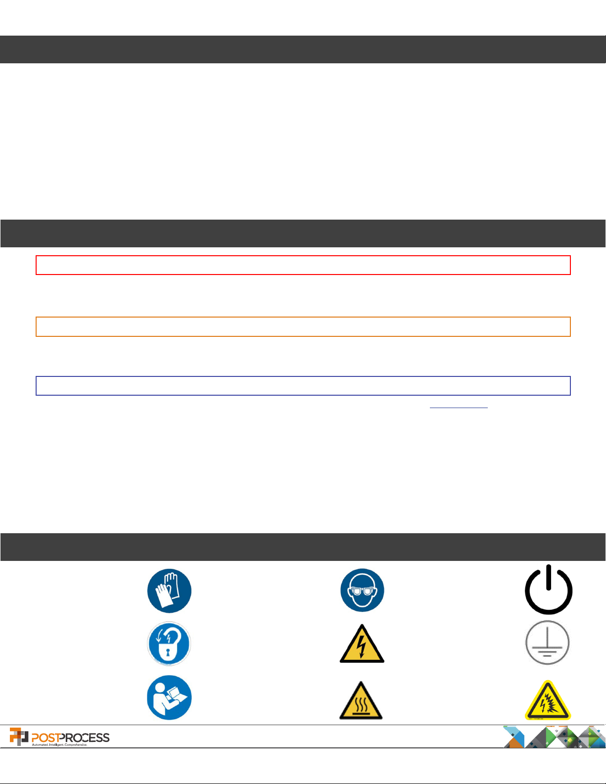
Safety Pictograms
Use Nitrile Gloves
Use Eye Protection
Power On /
Power Off
Lockout / Tagout
Consult Operator’s
Manual
PostProcess Technologies, Inc. • www.postprocess.com • REV A | page 2
Electrical Hazard
Caution Hot Surface
Grounding /
IEC Earth Symbol
Arc Flash Hazard

Table of Contents
Overview 5
Warnings, Cautions and Notes 5
Physical Description 7
1. Operation 9
1.1 Connecting Power to the DECI 9
1.2 Powering Up the DECI 10
1.3 Automatic Operation - Setup/Start 11
1.3.1 Auto Setup Controls 12
1.3.2 System Information 13
1.3.3 Features 14
1.3.4 Setting Auto-Temperature Operation 15
1.3.5 Setting Auto-Drain/Dose Operation 16
1.3.6 Recipe Management 16
1.3.7 Auto Run Mode 18
1.4 Manual Operation Screens 20
1.4.1 Manual Motion 22
1.5 Maintenance Operations 23
1.5.1 Filter Screen Maintenance 24
1.5.2 pH Sensor Maintenance 25
1.5.3 Dosatron Maintenance 26
1.6 Alarms and Warnings 28
1.6.1 Alarm Conditions 28
1.6.2 Warning Conditions 29
2. Dosatrons 30
2.1 Priming the Dosatrons 30
3. Troubleshooting 31
3.1 There is a decrease in water/detergent ow, or the ow has stopped. 31
3.2 The ALARM BUTTON is lit up and the DECI will not operate. 31
3.3 The DECI Controller touchscreen is not reacting properly. 31
3.4 Water or liquids are leaking inside of or around the DECI. 31
3.5 The internal passages of the part are not being fully cleaned. 31
3.6 The lter screen and particle lter have buildup or blockages. 32
3.7 The liquid temperatures are running too hot or too cold. 32
3.8 There is excess foam in the processing chamber. 32
3.9 The DECI is not stationary or stable 32
3.10 Where can I nd the DECI Serial Number? 32
4. Point of Contact 33
5. Revision History 33
6. Appendix A 34
Conguration Settings 34
Agitation Settings 35
Setup 38
7. Appendix B 46
Noise 46
Moving the Machine 46
Decommisioning and Disposal 47
Spare Parts List 47
CE Declaration of Conformity 48
PostProcess Technologies, Inc. • www.postprocess.com • REV A | page 3

List of Figures
Figure 1. Location of Master Power Switch 9
Figure 2. Master Power Switch “ON” 9
Figure 3. Power Connector 9
Figure 4. Controller Screen, Power Button, and Emergency Stop Button 10
Figure 5. Automatic Operation Screen - Setup/Start 11
Figure 6. Auto Setup Screen 12
Figure 7. Hardware Status 13
Figure 8. System Information Screen 14
Figure 9. Features Enabling Screen 14
Figure 10. Auto-Temperature Conguration Screen 15
Figure 11. Recipe Save As Screen 16
Figure 12. Recipe Overwrite Warning Screen 17
Figure 13. Enter Recipe Name Screen 17
Figure 14. Recipe Selection Screen 17
Figure 15. Auto Run Screen 18
Figure 16. Auto Run Warning Screen 19
Figure 17. Home Screen 20
Figure 18. Manual Operations Screen 20
Figure 19. Manual Motion Screen 22
Figure 20. Filter Screen Maintenance Screen 23
Figure 21. pH Sensor 25
Figure 22. pH Sensor Maintenance Screen 25
Figure 23. Dosatron Maintenance Screen 26
Figure 24. Dosatrons 27
Figure 25. Alarms and Warnings Screen 28
Figure 26. Dosatrons Conguration 30
Figure 27. Caster with Ratchet 32
Figure 28. Conguration Screen 35
Figure 29. Level 1 Agitation Valve Conguration Screen 35
Figure 30. Agitation Valve Conguration Screen 36
Figure 31. Segments Screen 36
Figure 32. Run Time Screen 37
Figure 33. Taper Screen 37
Figure 34. Level 0 Screen 38
Figure 35. System Conguration Screen 38
Figure 36. Auto-Temperature Conguration Screen 39
Figure 37. Heater Conguration Screen 40
Figure 38. Heater Conguration Screen 2 41
Figure 39. Over Temperature Conguration Screen 41
PostProcess Technologies, Inc. • www.postprocess.com • REV A | page 4
Overview
This User Manual is intended to explain the setup and operation of the DECI Support Removal
machine. Read this guide thoroughly before operating the DECI to ensure safe and efcient
operation. If a question is not answered in this guide, contact PostProcess for additional support.
The DECI applies patent-pending technology, including optimized energy through agitation in combination with
proprietary, eco-friendly detergents and heat to remove excess material deposited during 3D printing processes.
While the DECI is robust, care should be used during operation. When accessing the main chamber, gently open
and close the chamber door. Be careful when extracting nished parts to limit the amount of detergent that is
lost during the part removal process. Ensure no heavy materials are stored above the DECI that may fall and
damage it.
Warnings, Cautions and Notes
Ventilation
PostProcess Technologies detergents are specically formulated chemistry for maximized 3D printed support
removal efciency. It is recommended that the equipment be located in a well ventilated room. Specic
ventilation requirements can vary widely due to size of the install room, existing ventilation (positive or negative)
and differences in individual sensitivities to airborne scents or fragrances. For more information on the safe use
of PostProcess detergents refer to the SDS for the specic detergent used.
Warnings
Failure to adhere to any of the warnings below could result in personal injury or damage to equipment.
Improper
the machine. If the machine appears to be malfunctioning in any way, immediately PUSH the
EMERGENCY STOP button and refer to the Troubleshooting section of this guide on page 31. If the
issue is not able to be resolved, call PostProcess Support.
Caution should be used whenever working with industrial-powered equipment. If there is an emergency situation,
it is important to note that hitting the EMERGENCY STOP button does not turn off power to the DECI. It turns off
the DECI’s operating cycle only. To shut off power to the DECI, turn off the MASTER POWER SWITCH, located on
the front left panel of the DECI. (For a visual of the switch location, see Figure 1. Location of MASTER POWER
SWITCH)
use of PostProcess equipment may void the warranty. Read thoroughly before operating
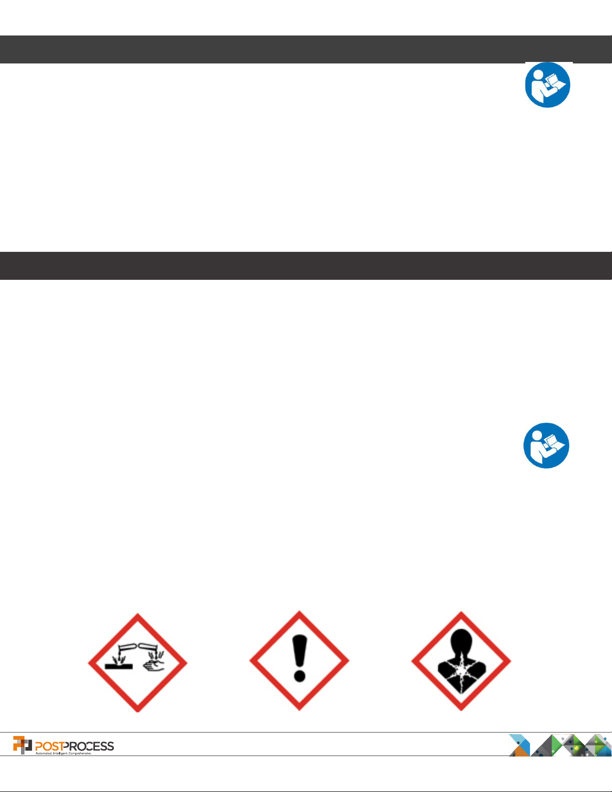
GHS Hazards
PostProcess Technologies, Inc. • www.postprocess.com • REV A | page 5
Warnings, Cautions and Notes
Environmental Temperature and Humidity
The operating environmental temperature must be between 10°C and 40°C (50°F to 104 °F), and humidity
between 20% and 80% relative humidity, non-condensing.
Foreseeable Misuse
• Do not operate the unit without proper grounding.
• Do not allow alcohol, gasoline or other ammable solutions near the machine. Doing so could
cause a re or explosion.
• Do not attempt to disassemble or repair the machine.
• Do not place the power cord in a location where it may come into contact with water or liquids.
• Connect the unit only to three-phase 400v power 50Hz.
• Use only PostProcess detergents. Do not add any other liquid solutions to the machine.
• Do not operate the machine without sufcient detergent in the tank.
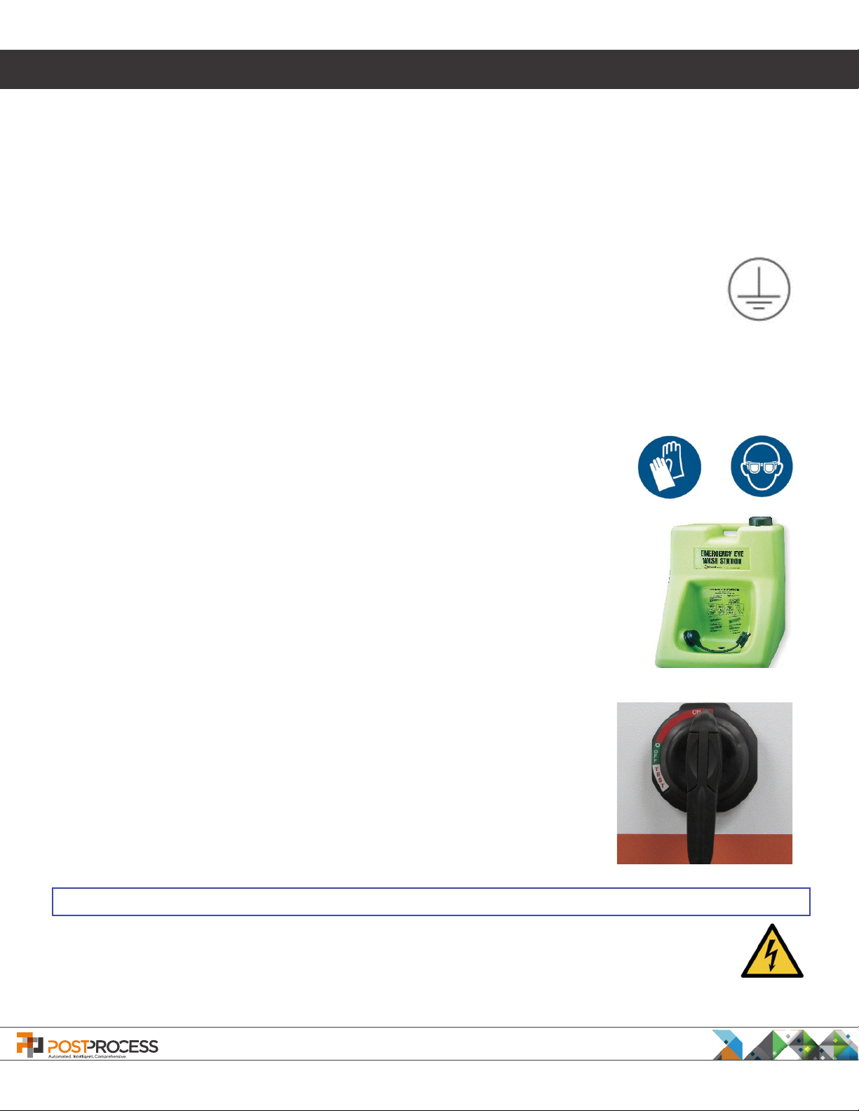
Residual Risks
• Do not touch the detergent with bare skin. Use nitrile gloves, laboratory-style
eyeglasses and other necessary personal protective equipment when performing
any operations including removing parts where skin could come into contact with
the detergent.
• When working with or near detergents, always wear nitrile gloves.
• Wear laboratory-style protective glasses.
• If bare skin comes in contact with detergent, thoroughly wash the body part with
soap and warm, clean water.
• It is recommended that an eyewash station is near the DECI and any detergent
storage areas.
Electrical Safety
Caution should be used whenever working with industrial-powered equipment.
If there is an emergency situation, it is important to note that hitting the
EMERGENCY STOP button does not turn off power to the DECI. It turns off the
DECI’s operating cycle only. To shut off power to the DECI, turn off the MASTER
POWER SWITCH, located on the left-side panel of the DECI.
NOTE
The EMERGENCY STOP button should only be used in actual emergency situations. For any other
situation requiring the machine to be powered down, use the MASTER POWER SWITCH.
PostProcess Technologies, Inc. • www.postprocess.com • REV A | page 6
Physical Description
Power and Electrical
Phases: 3 Voltage: 400 Amperage: 30
Cord: 5 wire Lapp ÖLFLEX® Gauge: 8
Plug: Hubbell HBL516P6W (1.83 m cord)
Recommended Connector or Receptacle:Hubbell HBLS530C6W* (Female Connector) or
Hubbell HBLS530R6W* (Female Receptacle) and BB2030N* (housing)
*Not supplied with machine
NOTE
High Leakage Current - Earth connection essential before connecting supply. Incoming Primary Earth conductor
must be a minimum of 10mm2 CSA.
Size and Weight
External Dimensions (Doors Open):
Length: 1.13 m Width: 2.09 m Height: 2.54 m
External Dimensions (Doors Closed):
Length: 1.13 m Width: 1.03 m Height: 2.38 m
Note: This height is measured to a removable stack light. The maximum xed height (with stack light
removed) is 2.12 m.
Approximate Weights:
Empty: 317.5 kg Full: 453.6 kg
Envelope and Capacity
Internal Envelope Dimensions:
Length: .48 m Width: .7 m Height: .66 m
The maximum tank capacity is approximately 75.7 liters.
The maximum part weight for the xture is 22.7 kg.
PostProcess Technologies, Inc. • www.postprocess.com • REV A | page 7
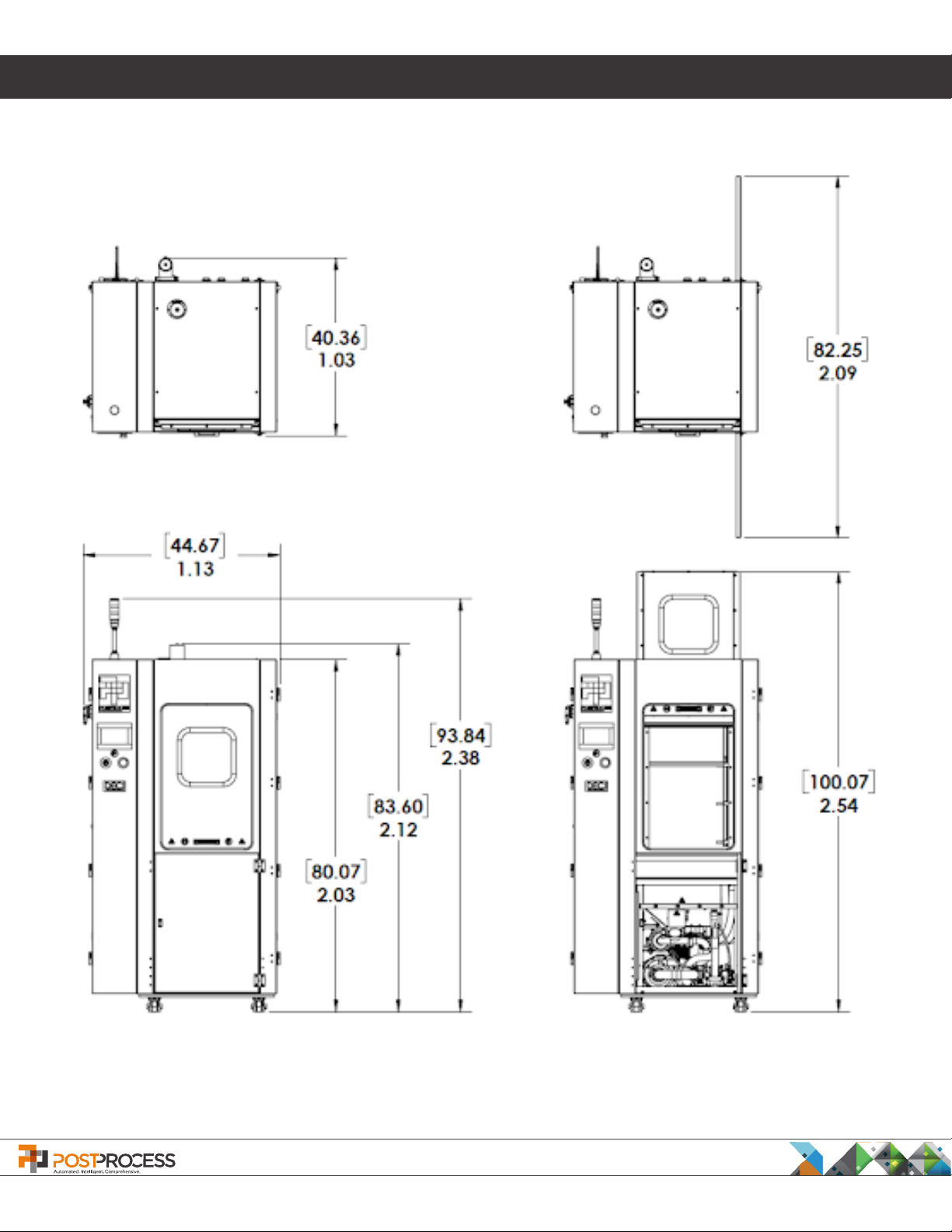
Physical Description
Dimension Drawings
Closed-door dimensions Open-door dimensions
PostProcess Technologies, Inc. • www.postprocess.com • REV A | page 8

1. Operation
1.1 Connecting Power to the DECI
The DECI is delivered with an industrial power cord. Use only the power cord supplied by PostProcess with the
DECI. Connect the DECI only to 3-phase 400v power 50Hz. Do not place the power cord in a location where it
could come into contact with water or other liquid substances. It is recommended to keep the entire power cord
suspended above the oor surface.
The MASTER POWER SWITCH is located on the left side of the DECI in the upper right corner (Figure 1.
Location of Master Power Switch). Before connecting or disconnecting the DECI to a power outlet, or inserting
or removing the power cord, ensure the MASTER POWER SWITCH is in the horizontal “O” or OFF position (Figure
2. Master Power Switch “ON”).
When the power cord is connected to the DECI and plugged into a 3-phase 400v 50Hz power outlet, turn the
POWER switch 90 degrees clockwise to the vertical “I” or ON position. The DECI is now ready to be powered up.
Figure 1. Location of Master Power Switch
The Master Power Switch is located
on the left side in the upper right corner.
The DECI utilizes 400v 50Hz power
provided through an industrial power
cable/connector located on the upper
rear of the unit as shown in Figure 3.
Power Connector.
PostProcess Technologies, Inc. • www.postprocess.com • REV A | page 9
Figure 2. Master Power Switch “ON”
To turn off the Master Power Switch grab
the handle and rotate counter clockwise
90° to the OFF position.
Figure 3. Power Connector
1. Operation
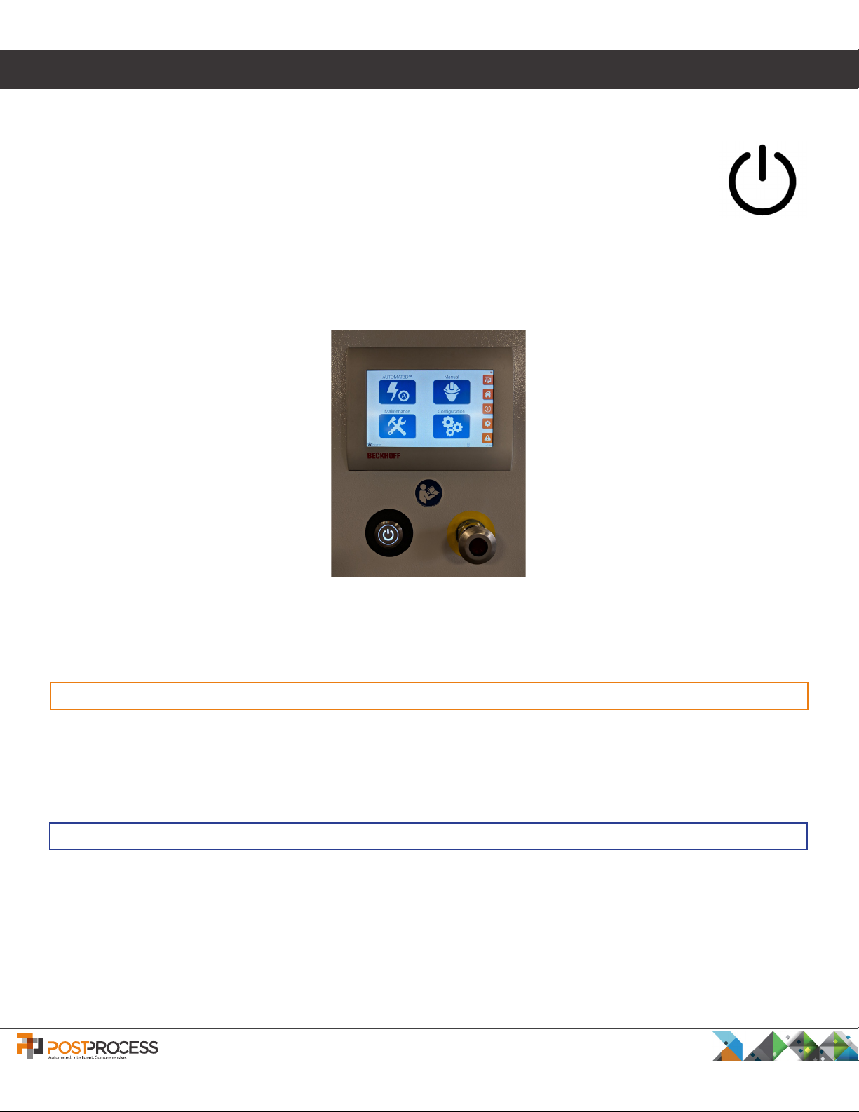
1.2 Powering Up the DECI
The POWER button for the DECI is located to the lower left of the Controller Touchscreen (Figure
4. Controller Screen, Power Button, and Emergency Stop Button). To power up (or down) the
DECI, press the POWER button. If the POWER button is illuminated, the DECI is on.
Below the Controller Touchscreen on the right is the Emergency Stop button (shown below, right)
Figure 4. Controller Screen, Power Button, and Emergency Stop Button
CAUTION
If the DECI appears to be malfunctioning in any way, immediately PUSH the EMERGENCY STOP button and
refer to the Troubleshooting section of the Manual. If the issue is not able to be resolved, contact PostProcess
Support.
NOTE
If the DECI is not used for a period of time it may be necessary to run the heater in Manual Mode to bring
detergent in the tank up to the appropriate operating temperature. Please see Section 1.4 Manual Operations
more information on how to increase operating temperatures. For more information on how temperature impacts
post-processing, see Appendix A.
the
for
PostProcess Technologies, Inc. • www.postprocess.com • REV A | page 10
1. Operation
1.3 Automatic Operation - Setup/Start
The DECI is designed to be fully automatic and congured to
remove supports from the following 3D print technologies:
FDM, SLA, CLIP, Polyjet, and others. The DECI is engineered to
utilize an automated Volume Velocity Dispersion system that
is congurable based on a specic operational need. To learn
more please refer to DECI Conguration Settings.
The top side of the DECI houses the envelope (or chamber).
The envelope is roughly 47cm x 65cm x 74 cm (18” x 25 1/2” x
29”). The door utilizes a counterweight system to keep it open
once opened, yet caution should be used when reaching into the
chamber.
NOTE
Whenever an operator is handling detergents, nitrile gloves and eye glasses should be worn.
To begin the support removal cycle, press the POWER button to ON and wait for the Main Menu screen to display.
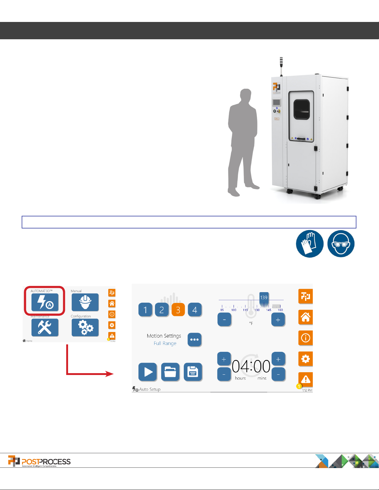
Figure 5. Automatic Operation Screen - Setup/Start
To access the Automatic Operation screen (Figure 5. Automatic Operation Screen - Setup/Start), from the
Home screen press the AUTOMAT3D™ button. The cycle settings are selected on the Auto Setup screen. The
DECI will retain the settings from the previous cycle. If no changes need to be made, press the START icon to
begin the cycle. If new settings are required, see Section 1.3.1 Auto Setup Controls.
PostProcess Technologies, Inc. • www.postprocess.com • REV A | page 11
1. Operation
1.3.1 Auto Setup Controls
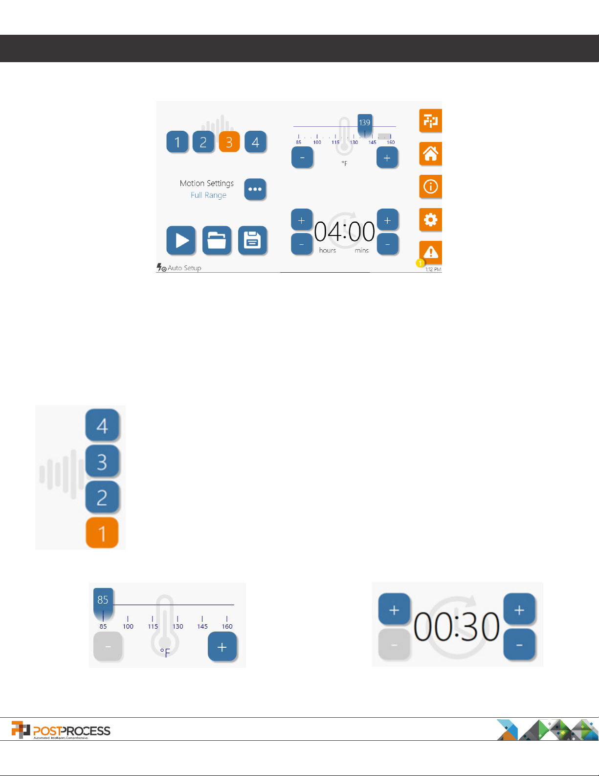
Figure 6. Auto Setup Screen
Three settings can be congured on the Auto Setup screen (Figure 6. Auto Setup Screen). The settings must be
properly congured based on the unique properties of the parts to be processed by the DECI and are discussed
in greater detail below.
At the upper, left are four buttons that control the Agitation (Energy) Level by conguring the spray nozzles
to operate in a predetermined sequence. These settings are congured by PostProcess personnel during the
installation process. For detailed information about conguring the settings, see the DECI Appendix A.
Press (4) for High Agitation – bottom spray nozzles and the upper narrow-angle nozzles all
operate for the highest agitation.
Press (3) for Medium Agitation– bottom spray nozzles, one upper narrow-angle nozzles and
the upper wide angle nozzles operate for higher agitation.
Press (2) for Low Agitation – spray nozzle conguration for low level combination of bottom
nozzles and upper nozzles.
Press (1) for Ultra-Low Agitation –bottom spray nozzles only.
The selected Agitation Level turns ORANGE while non-selected levels remain BLUE.
Temperature Control – Use the slider to set the desired
temperature of the detergent in the tank. The operator can
also use the + / - to adjust the temperature.
PostProcess Technologies, Inc. • www.postprocess.com • REV A | page 12
Run Time - To set the desired run time for
the automatic cycle use the + / - to adjust
the Hours (Left) and Minutes (Right).
1. Operation
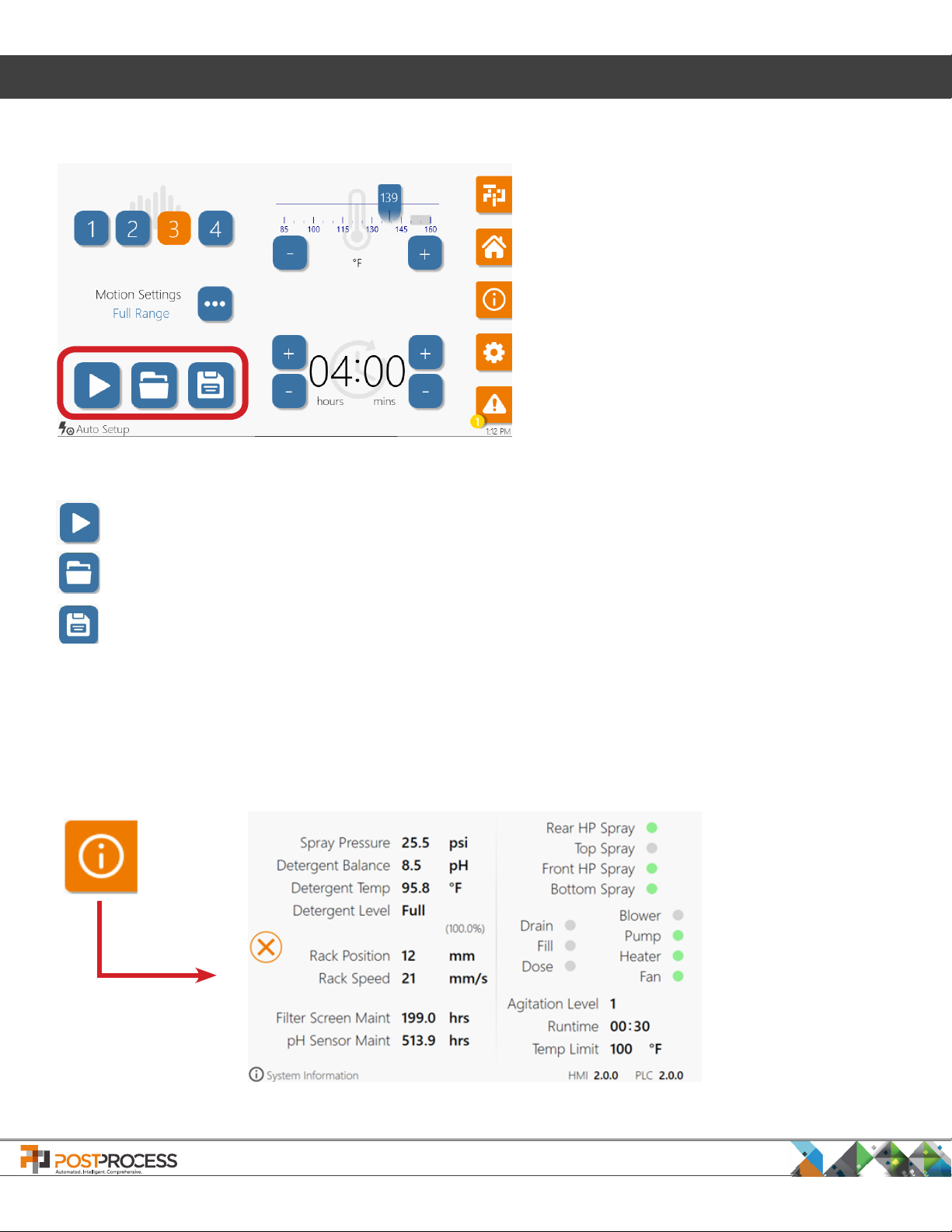
The icons on the right of the screen control access to basic functions.
LIGHT - Turns the chamber light on/off
HOME - Returns to the Home Screen.
INFO - For machine data.
CONFIGURATION - For basic system settings.
ALERTS - Displays Alarm conditions.
(See Section 1.6 Alarms and Warnings).
After adjusting the settings to their appropriate levels for the part to be cleaned press the START button
on the left side of the screen (as shown above).
To select a Recipe having the desired settings (See Section 1.3.6 Recipe Management) press the
SELECT RECIPE button.
To save newly created Automatic Cycle settings as a Recipe for future use (See Section 1.3.6 Recipe
Management) press the SAVE RECIPE icon.
1.3.2 System Information
The operator can access basic system information by pressing the INFORMATION button from any screen.
Figure 7. Hardware Status
PostProcess Technologies, Inc. • www.postprocess.com • REV A | page 13
1. Operation
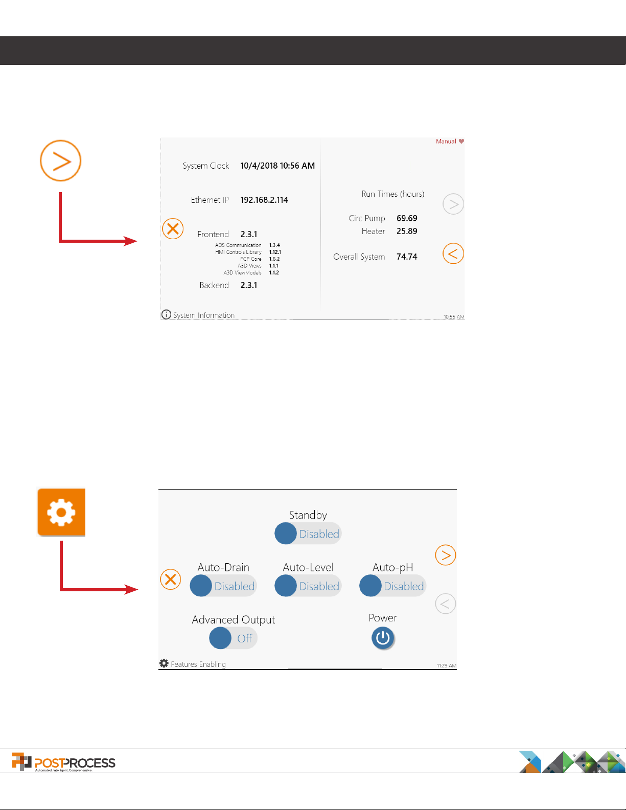
When multiple pages are available, the screen will have a right/left arrow to allow navigation between the screens
(Figure 8. System Information Screen). To close the Information screens, press the X.
Figure 8. System Information Screen
1.3.3 Features
When the FEATURES button is pressed, the operator has access to basic operational functions
9. Features Enabling Screen the Features menu has three areas that can be adjusted.
Press the X button
to exit the Features
screen. A conrmation
will display.
Figure 9. Features Enabling Screen
Press the RIGHT
ARROW to access
the Auto-Drain/Dose
Conguration Screen.
. As shown in Figure
PostProcess Technologies, Inc. • www.postprocess.com • REV A | page 14
1. Operation
Standby –
allow the detergent
TEMPERATURE button should be enabled if the tank needs to be kept at a constant temperature between
cycles. If AUTO-TEMPERATURE is not enabled, the DECI tank heater will need to be run manually to bring the
temperature up to the desired level before starting the cycle.
Auto-Drain – When enabled, the tank will automatically drain after the completion of a user dened amount of
auto cycles.
Auto-Level - When enabled, the tank level will be monitored at a user dened interval. If the tank level drops
below a predened level the tank will be automatically dosed back to 100%. A message will appear to inform the
operator.’
Auto-pH - When enabled, the tank’s pH will be monitored. If the pH falls below the Minimum Operational pH Level
a warning will become active and the tank will be automatically drained and re-dosed to correct the pH level. A
message will appear to inform the operator.
Advanced Output – If enabled, system data is collected for PostProcess Support.
Light Stack Test – When pressed the light stack will illuminate so the operator can verify that the lights are
operational. The light stack should be tested at the beginning of each shift.
Because heat is an important component of post-processing, the DECI has functionality built-in to
to be maintained at a certain temperature when the machine is not in use. The AUTO-
Power – When pressed a menu will appear for restarting the PC, shutting down the PC, or exiting the application.
1.3.4 Setting Standby Operation
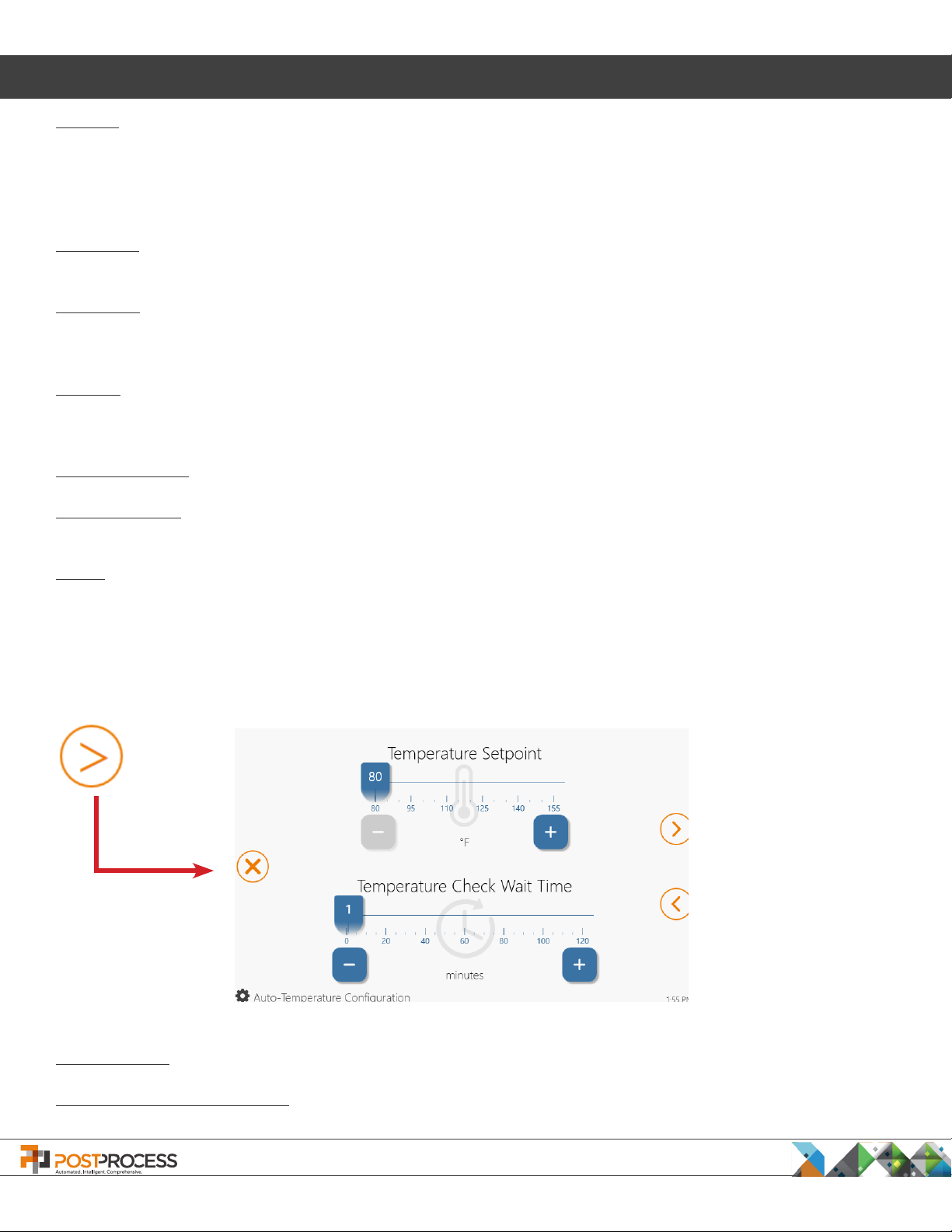
Once the
To access the settings, press the “right arrow” from the Features Enabling Screen.
Press the X button
to exit the Auto-
Temperature screen.
A conrmation will
display.
AUTO-TEMPERATURE
Figure 10. Auto-Temperature Conguration Screen
is enabled, the operator can adjust the Auto-Temperature Conguration settings.
Press the LEFT ARROW
to return to the
Features screen.
Temp Setpoint – Use the slider bar to set the desired tank temperature for Auto-Temperature mode.
Temperature Check Wait Time – Sets the time between temperature checks while in Auto-Temperature mode.
PostProcess Technologies, Inc. • www.postprocess.com • REV A | page 15
 Loading...