


Operational Instructions
OBM-N180
OBM-N210
OBM-N240
OBM-N310
OBM-N420
OBM-N460
OBM-N550
User Manual
07. 2017
OBM N Series
Professional Video Monitor

Table of Contents
1. Precaution
2. Main Features
3. Location and Function of Parts and Controls
Front Panel
Rear Panel
4. Using the Menu
5. Adjustment Using the Menus
6. OSD Menu Operations
Status Menu
Color Temp/Color Space/Gamma Menu
Zebra/Focus Menu
User Conguration Menu
Remote Menu
Security Menu
7. Key Functions
8. Available Signal Formats
9. Product Specications
3
5
6
8
10
11
13
14
16
16
20
21
22
24
26
BM-N Series
2
Professional Video Monit
or
Outstanding Picture Qualit
y

3
1. Precaution
Always use set voltage.
AC 100 ~ 230V, 50/60Hz
DC 12V(OBM-N180/N210/N240) or DC 24V(OBM-N310)
All these instrucons should be read and understood before operang the unit.
If liquid is spilled on or impacts this product, please disconnect the product immediately and seek professional help before connued use.
Unplug the unit from the wall outlet if it is not to be used for several days or more.
Keep unit in a well-venlated place to prevent overheang.
Do not install the product near any heat-generang equipment. Also, keep the product out of direct sunlight
or dusty areas.
Protect the power cord from being walked on or pinched parcularly at plugs, convenience receptacles, and
the point where they exit from the apparatus.
When using other DC 12V(OBM-N180/N210/N240) or DC 24V(OBM-N310) adapters instead of the standard
adapter provided by the manufacturer, please check the proper load capacity or current capacity and use an
adapter with stable voltage.
Do not overload AC outlets or extension cords. Overloading can cause fire or electric shock.
A very small proporon of pixels may be stuck, either always off (black), always on (red, green, or blue), or
flashing. In addion, over a long period of use, because of the physical characteriscs of the liquid crystal
display, such stuck pixels may appear spontaneously. These problems are not a malfuncon.
If a fixed picture such as a frame of a divided picture or me code, or a sll picture is displayed for a long me,
an image may remain on the screen and be superimposed as a ghosng image.
The permanent burn-in may occur for LCD panel if sll images are displayed in the same posion on the
screen connuously, or repeatedly over extended periods.
To reduce the risk of burn-in,
a. Turn off the character displays.
b. Turn off the power when not in use.
c. Turn off the power if the monitor is not to be used for a prolonged period of me.
BM-N Series
Professional Video Monit
or
Outstanding Picture Qualit
y

4
Do not aempt to service the product yourself. Removing covers can expose you to high voltage and other
dangerous condions. Request a qualified service person to perform servicing.
When the product needs replacement parts, make sure that the service person uses replacement parts
specified by the manufacturer, or those with the same characteriscs and performance as the original parts.
Use of unauthorized parts may result in fire, electric shock and/or other danger.
Only clean the product with a noncommercial, mild and neutral detergent.
Do not throw away the carton and packing materials. When transporng the product, make use of its original
packaging for safer carriage.
FCC (Federal Communications Commission)
This equipment has been tested and found to comply with the limits for class A digital device, pursuant
to part 15 of the FCC Rules. These limits are designed to provide reasonable protecon against harmful
interference when the equipment is operated in a commercial environment. This equipment generates,
uses, and can radiate radio frequency energy, and if not installed and used in accordance with the
instrucon manual, may cause harmful interference to radio communicaons. Operaon of this
equipment in a residenal area is likely to cause harmful interference in which case the user will be
required to correct the interference at his own expense.
Warning!! : Changes or modificaons not expressly approved by the manufacturer could void the
user’s authority to operate the equipment.
Disposal of Old Electrical & Electronic Equipment
(Applicable in the European Union and other European countries
with separate collecon systems)
This symbol on the product or on its packing indicates that this product shall not be treated as
household waste. Instead it shall be handed over to the applicable collecon point for the recycling of
electrical and electronic equipment. By ensuring this product is disposed of correctly, you will help
prevent potenal negave consequence for the environment and human health, which could otherwise
be caused by inappropriate waste handling of this product. The recycling of materials will help to
conserve natural resources.
!
BM-N Series
Professional Video Monit
or
Outstanding Picture Qualit
y

5
2. Main Features
The OBM N series offers the superior picture quality and wide viewing angle, and includes an array of
professional features and the advanced audio & video signal analysis funcons including Waveform, Vector
Scope, Audio Level Meter, IMD, Camera Log Selecon, Custom 3D LUT Import, Focus Assist, etc. The OBM N
series are equipped with various I/O interfaces such as 3G-SDI, HDMI, Component, Composite, DVI. The wide
model lineup from 18.5” up to 55” provides the best soluons from the field producon to monitoring in
studio.
- 3G/HD/SD-SDI 2 Channel
- HDR(High Dynamic Range) Display supporng PQ EOTF(ST 2084),
Hybrid Log Gamma, S-Log3
- 3D-LUT for Accurate Color Reproducon
- 1.064 Billion Colors
- Camera Log Conversion
- Camera Log Mapped SDI Loopout
- Custom 3D LUT File Import Through USB
- Gamma Selecon (1.0 ~ 3.0)
- Color Temperature(3200K, 5500K, 6500K, 9300K, USER 1/2/3, D-CINEMA)
- HDR & Camera log Compare (Side by Side, Wipe Posion)
- Waveform, VectorScope (Wave + Vector, Waveform Wide, Posion Change, Size Adjustment)
- Monitor Control via Ethernet, RS-422
- Various Markers (EBU, 4:3, 16:9, 1.85:1, 2.35:1, Variable etc.)
- White Internal Paerns Display for Color Test
- Easy Firmware Update by USB
- Fast Mode
- Focus Assist
- Zebra
- HDR Waveform
- Zero Scan / 1:1 Scan
- H/V Delay
- Blue/Mono Only
- Time Code Display
- IMD
- De-embedded 8~16ch Audio Level Meter
- Remote Control via GPI(RJ-45) Port
- 3 Color TALLY Lamp
- Rack & VESA Mount (Opon)
- Closed Capon(608, 708)
- System Data Copy
- Key Lock & Password Lock
- Aspect
- Freeze
BM-N Series
Professional Video Monito
r
Outstan
d
ing Picture Qualit
y
6
3. Location and Function of Parts and Controls
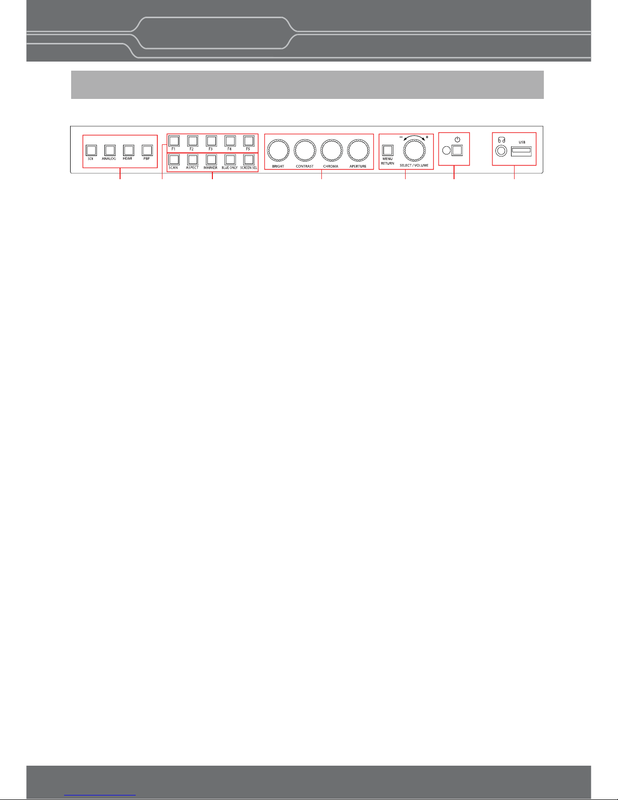
Front Panel
A : Input select Buons/Lamp
Press to monitor the signal input to each connector.
[SDI-A] Buon/Lamp
- Press the buon to select 3G SDI-1 input
[SDI-B] Buon/Lamp
- Press the buon to select 3G SDI-2 input
[ANALOG] Buon/Lamp
- Press the buon to select Analog Input.
- Mode changes in the order of [Composite] [Component].
[DIGITAL] Buon/Lamp
- Press the buon to select Digital input.
- Mode changes in the order of [HDMI] [DVI].
B : F1 ~ F5 Buon/Lamp
Press to adjust or turn on/off the assigned funcon.
The following funcons are assigned at the factory.
[F1]: HDR&Cam.Log Compare
[F2]: H/V Delay
[F3]: Color Temp
[F4]: Audio Level Meter
[F5]: Time Code
C : Funcon Buon/Lamp
Press to adjust or turn/off each funcon.
[SCAN] Buon - Press the buon to adjust the scan mode. (Zero Scan, 1:1 Scan).
[ASPECT] Buon - Press the buon to select the Aspect Rao of the signal.
- Mode changes in the order of [16:9] [4:3] [2.35;1] [1.85:1] [15:9] [16:10] [AUTO].
[MARKER] Buon
- Press the buon to acvate and deacvate the Marker.
[BLUE ONLY] Buon
- Press the buon to acvate and deacvate the Blue Only funcon.
- You may remove R(red) and G(green) from the input signal and play the screen only with B(blue) signal.
This funcon is convenient to adjust Chroma and Phase and to observe the signal noise.
- The buon may be pressed twice to change the screen to MONO mode.
(This mode uses only Luminance value)
[KEY LOCK] Buon - Press the buon to lock all buons except Power
D : Rotary encoder
[BRIGHT] knob
Press this knob to display the adjustment screen and adjust the picture brightness. Press again to hide the
adjustment screen. Turn the knob right to increase the brightness and turn le to decrease it.
[CONTRAST] knob
Press this knob to display the adjustment screen and adjust the picture contrast. Press again to hide the
adjustment screen. Turn the knob right to increase the contrast and turn le to decrease it.
AB C D E F G
BM-N Series
Professional Video Monito
r
Outstan
d
ing Picture Qualit
y

7
[CHROMA] knob
Press this knob to display the adjustment screen and adjust the color intensity. Press again to hide the
adjustment screen. Turn the knob right to increase the color intensity and turn le to decrease it.
[APERTURE] knob
Press this knob to display the adjustment screen and adjust the picture sharpness. Press again to hide
the adjustment screen. Turn the knob right to make the picture sharper and turn it le to make the
picture soer.
E : Menu Operaon Buons
Displays or sets the on-screen menu.
[MENU/RETURN]
- Acvates and deacvates the display of the Main Menu.
- When the on-screen menu is not displayed, if this buon is pressed the main menu is displayed.
When the menu is displayed, press the buon to return to the previous menu.
[SELECT/VOLUME] knob (Menu selecon control)
- When the menu is displayed, turn the knob to select a menu item or seng value, and then press the
knob to confirm the seng.
- If the menu is not displayed and this knob is pressed, the adjustment screen of [VOLUME] is displayed
to adjust the audio volume.
- Press this knob to change the modes in the order of [Focus Frequency] [Zebra Level] [Line Posion]
[Variable Marker] and adjust each mode’s value.
[Focus Frequency]: When Focus Assist funcon is acvated, this mode is displayed.
[Zebra Level]: When Zebra funcon is acvated, this mode is displayed.
[Line Posion]: When WFM/Vector funcon and Line Select funcon is acvated, this mode is displayed.
[Variable Marker]:
When Marker funcon is acvated and Aspect Marker is set Variable, this mode is displayed.
F : (Standby) switch and indicator
- Press to turn the power on when this monitor is in standby mode. Aer being turned on, the monitor
performs inializaon and the indicator flashes in green.
- Press the switch again for a second to set the monitor in standby mode. Then, the indicator flashes in
orange and then turns red. The indicator in orange means that the monitor goes into the standby
mode.
When the indicator flashes in orange, this buon doesn’t work.
G : (headphone) jack & Speaker and USB connector
Headphone jack & Speaker
- The audio signal which is selected using the input select buon is output in stereo sound.
- When SDI signals are input, the audio signals of the channels selected with SDI Audio Seng in the User
Configuraon menu are output.
- When the headphones are connected to the jack, audio signals will not be output.
[USB] Connector
- To update CPU, GPU, FPGA program.
- To connect the monitor with the Color Calibraon program provided by the manufacturer and perform
the color calibraon.
- To connect the monitor with the control program provided by the manufacturer and control funcons
remotely.
- Custom 3D LUT File Import via USB memory sck or pc(*.cube, 33^3, 65^3)
BM-N Series
Professional Video Monito
r
Outstan
d
ing Picture Qualit
y

8
Rear Panel
A : SDI IN (SDI Input) connectors (BNC)
Input connectors for SDI signals. For details, see “Connecng the SDI Signals” (page 26).
B : SDI OUT (SDI Output) connectors (BNC)
Output connectors for SDI signals.
Each connector outputs the signal which is input to the corresponding SDI IN connector.
**Note - Output is acvated only when the power is on. Output is not acvated in standby mode.
C : Analog input connectors
Input connectors for analog signals (CVBS, Component).
D : HDMI input connectors
Input connectors for HDMI signals.
E : DVI-D Input connector
Input connector for DVI signal.
F : PARALLEL REMOTE connector(RJ-45, 8-pin)
Forms a parallel switch and controls the monitor externally.
**Note - For safety, do not connect the connector for peripheral device wiring that might have excessive
voltage to this port. Follow the instrucons about this port.
[Pin Assignment]
Funcons can be changed in [Remote] secon of the menu.
1
8
Pin Number Funcon
SDI
HDMI
Analog
Digital
1:1 Scan
Aspect
Power
GND
1
2
3
4
5
6
7
8
A
B
C
D
F
E
H
IG
BM-N Series
Professional Video Monito
r
Outstan
d
ing Picture Qualit
y

9
DC IN Socket
1 : GND
4 : +12V
4
12
3
DC IN Socket
1 : GND
4 : +24V
4
12
3
G : SERIAL REMOTE IN/OUT connector (RJ-45)
Used for the future funcon expansion.
Connects the monitor to the control program provided by the manufacturer by using RS-422/485
communicaon or the external UMD(IMD) equipment and controls the monitor.
H : LAN(10/100) IN/OUT connector
Used for the future funcon expansion.
Connects to the LAN (10/100) connector of the network by using 10BASE-T/100BASE-TX LAN cable.
A daisy chain connecon using the LAN input/output connectors enables the control of mulple monitors in
sequence.
I : AUDIO IN connector (Stereo mini jack)
Connector for analog audio input.
Analog input can be selected with SDI Audio Seng in User Configuraon menu.
J : DC IN terminal
Connects the DC power supply to the monitor.
- OBM-N180 / N210 / N240 : 12V
- OBM-N310: 24V
Make sure to use DC 12V power supply for OBM-N180/N210/N240 and DC 24V power supply for
OBM-N310.
OBM-N180/N210/N240 OBM-N310
K : AC IN terminal
AC power input connector.
Connects the provided AC power cord.
OBM-N Series
Professional Video Monit
or
Outstanding Picture Qualit
y

10
4. Using the Menu
BM-N Series
Professional Video Monit
or
Outstanding Picture Qualit
y
This monitor is equipped with an OSD menu to make various adjustments and sengs such as picture control,
input seng, set seng change, etc.
1. Press the MENU buon.
The menu appears.
The menu presently selected is shown in gray.
3. Select an item.
Turn SELECT/VOLUME knob to select the item, then press the knob.
The item to be changed is shown highlighted, and the sub menu is displayed on the right.
4. Make the seng or adjustment on an item.
How to change the adjustment level:
To increase the level, turn the SELECT/VOLUME knob right.
To decrease the level, turn the SELECT/VOLUME knob le.
How to change the seng:
Turn the SELECT/VOLUME knob to change the seng, then press the knob to confirm the seng.
**Note - An item displayed in gray cannot be accessed. The item is accessible if it is displayed in white.
To return the display to the previous screen
Press the MENU buon.
To clear the menu
Press the MENU buon.

11
5. Adjustment Using the Menus
Color Temp./Color Space/Gamma menu
Color Temp. R/G/B Gain
Manual Adjustment
Color Space
OBM-HDR
Gamma
Gamma Log
Back Light
HDR&Cam.Log Comparison
Wipe Posion
User Configuraon menu
User Preset
Funcon Buon Seng
Input Seng
Speaker Out / Audio Level Meter Seng
SDI Le Speaker Out
SDI Right Speaker Out
HDMI L/R Speaker Out
Audio Level Meter
Marker Seng
Marker
Aspect Marker
Center Marker
Area Marker
Color
Aspect Mat
Fit
Thickness
WFM/Vector Seng
WFM/Vector
Closed Capon Seng
Closed Capon
Type
708
608
Fast Mode Seng
Fast Node
System Seng
TimeCode
Format
Color Temp
Brightness
Contrast
Chroma
Aperture
Color Space
Gamma
User Preset
RGB Range
Back Light
WFM/Vector
Audio Level Meter
Focus Assist
Time Code
Volume
SDI Payload ID
Model Name
Serial Number
Board Version
Operaon Time
Last Calibraon Time
Idenfier
Sampling
Picture Rate
Scanning Method
Bit Depth
Link Assignment
R Gain
G Gain
B Gain
R Bias
G Bias
B Bias
Copy From
The OSD menu of this monitor consists of the following items.
F1 Buon
F2 Buon
F3 Buon
F4 Buon
F5 Buon
3G Signal Format
RGB Range
Display
Reference
Size/Transparency
Peak Hold Time
Variable Aspect
Intensity
Transparency
Color
Line Select Line Posion
Posion
Size
WFM&Throughout w/ Camera log
Factory Reset
Internal Paern
Key LED
OSD Time
OSD posion
System Data
Status menu
(To indicate the current sengs)
Zebra/Focus menu
Zebra Level Adjustment
Focus Assist Color
Frequency
Default Log Sel.
User Log Sel.
BM-N Series
Professional Video Monit
or
Outstanding Picture Qualit
y

12
1 Pin
2 Pin
3 Pin
4 Pin
5 Pin
6 Pin
7 Pin
8 Pin
Parallel Remote
Monitr ID
In-Monitor Display Seng
IMD Type
Transparency
Text Color
Le Tally Color
Right Tally Color
Security Seng
Key Lock
Password
User Parameter Lock
Change Password
Remote menu
BM-N Series
Professional Video Monit
or
Outstanding Picture Qualit
y

13
6. OSD Menu
Operaons Status Menu
The Status menu displays the current status of the
monitor. The following items are displayed.
Page 1/4
Page 2/4
Page 3/4
Page 4/4
User Preset
RGB Range
Back Light
WFM/Vector
Audio Level Meter
Focus Assist
Time Code
Volume
SDI Input
SDI Payload ID
Idenfier
Sampling
Picture Rate
Scanning Method
Bit Depth
Link Assignment
**
The informaon on the SDI input signal of the Single
mode or the Le Side of P&P mode is displayed.
*** When the SDI signal is connected,
these items are displayed.
Format
Color Temp
Brigntness
Contrast
Chroma
Aperture
Color Space
Gamma
Model Name
Serial Number
Board Version
Operaon Time
Last Calibraon Time
BM-N Series
Professional Video Monito
r
Outstan
d
ing Picture Qualit
y
14
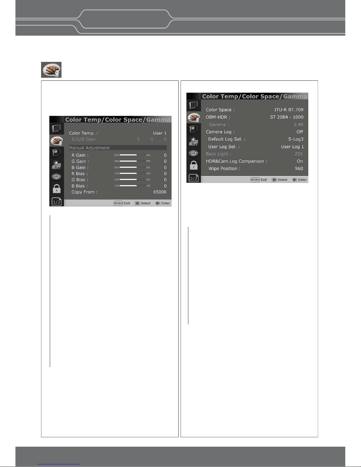
Color Temp/Color Space/Gamma Menu
Page 2/2
Color Space
- Selects the color space between [ITU-R BT.709],
[Nave].
OBM-HDR
Selects 4 modes of HDR gamma.
- ST-2084 1000: This mode displays the relave
brightness up to 1000cd/m². The part exceeding
1000cd/m² is clipped.
- ST-2084 10000 : The characteriscs of LCD panel
doesn’t allow to produce the ideal brightness
required by this standard, so the gamma is
displayed in the relave brightness.
- HLG -1.0 / 1.1 / 1.2 / 1.3 / 1.4 / 1.5 : These
modes allow the user to apply HLG from
1.0 up to 1.5.
- S-Log3: Select the S-Log3(HDR) gamma.
Gamma
- Selects the appropriate gamma mode from
1.00 to 3.00.
**Note - When the OBM-HDR is set Off, this
menu becomes acvated.
- When the color space is set to
Nave, this menu becomes
deacvated.
These menus are used for adjusng or seng the color
temperature, color space or gamma of the picture.
Page 1/2
**Note - If Color Space is set to [DCI-P3], Color
Temp. is fixed to [DCI-P3].
Color Temp
- Selects the color temperature from among
[3200K] [5500K] [6500K] [9300K] [User1]
[User2] [User3] [DCI-P3].
R/G/B Gain
- Displays the R/G/B Gain of the current
Color Temperature.
Manual Adjustment
- If you set the Color Temp. to User 1/2/3,
the item is changed from black to white,
which means you can adjust the color
temperature.
R/G/B Gain/Bias
- Adjusts the color balance(Gain, Bias).
Copy From
- The Gain and Bias data of each Color Temp.
are restored to User adjustment.
BM-N Series
Professional Video Monito
r
Outstan
d
ing Picture Qualit
y

15
Color Temp/Color Space/Gamma Menu
Camera Log
Selects a camera log for the input signal.
[Off]: Sets off the camera log.
[Default]:
The log which is selected in [Default Log Sel.]
menu is applied.
[User]: The log which is selected in [User Log Sel.]
menu is applied.
[Import Log Data]: Allows the user to save the Log
LUT in USB memory sck to the monitor.
The saved LUT can be used in User Log.
Default Log Sel.
Allows the user to select a camera log among
C-Log, Log-C EI 160~3200, S-Log2 To LC-709,
S-Log2 To LC-709TypeA, S-Log2 To Slog2-709,
S-Log2 To Cine+709, S-Log2 To LC-709, S-Log3
To LC-709TypeA, S-Log3 To Slog2-709, S-Log3
To Cine+709, J-Log1.
User Log Sel.
Selects User Log 1 to 4.
**Note
-
If you insert the USB memory sck which
contains the user log data to the monitor and
push Enter in [Import Log Data] menu, the
data is saved to the monitor.
- The file name of the user log data is displayed
on the OSD up to 15 characters, and the log
data file should be placed on the top folder of
the USB memory sck.
Ex) If the file name is ‘S-log3 to LC709_A.cube’,
it is displayed as ‘S-log3 to LC709’ on the
OSD.
Back Light
- Adjusts the level of the back light level.
If the back light value is increased, the screen
becomes brighter.
** If the seng in Color Temp. menu and
Color Space menu is changed, the value of
Back Light returns to the default value of
the color calibraon in the factory.
HDR&Cam.Log Comparison
Divides the screen side by side, applies HDR or
Camera log on the le side, and compares the
picture between the le side and the right side.
Wipe Posion
Adjusts the boundary line of the le and right
area. Allowed to adjust the boundary line by
using the SELECT/VOLUME knob
BM-N Series
Professional Video Monito
r
Outstan
d
ing Picture Qualit
y

16
User Conguration Menu
User Configuraon consists of the adjustment
menus such as[User Preset],[Funcon Buon
Seng],[Input Seng],[Speaker Out / Audio Level
Meter Seng],
[Marker Seng],[WFM/Vector Seng], [Closed
Capon Seng], [System Seng].
Page 1/7
User Preset
- Allows to check the adjustment status which
each user presets.
- All the adjustments the user sets are
automacally saved.
Funcon Buon Seng
- Assigns the funcon for F1 to F5 buons on
the front panel.
The following funcons can be assigned. :
[HDR&Cam.Log Compare],[H/V Delay],[ColorTemp.],
[Audio Level Meter],[Time Code],[Zebra],[Focus
Assist],[WFM/Vector],[Camera Log],
[Closed Capon], [OBM-HDR],[Freeze]
-
The following funcons are assigned in the factory.
[F1 Buon]: HDR&Cam.Log Compare
[F2 Buon]: H/V Delay
[F3 Buon]: Color Temp
[F4 Buon]: Audio Level Meter
[F5 Buon]: Time Code
Zebra/Focus Menu
Zebra
- Evaluates the Luma(Y’) level of the input image.
If the certain Y’ level is set, the pixels with the
designated Luma(Y’) level are displayed in
zebra paern.
** Pixels with Y’ level over 100% turn to red
zebra paern, and pixels with Y’ level under
0% turn to green zebra paern.
Level Adjustment
- Adjusts the Y’ level as the user wants.
Focus Assist
- Controls the aperture level of a video signal
and displays images on screen with sharpened
edges to help camera focus operaon.
Available types are [Color On] and [Mono On].
- [Color On]: The background image is the
original color type.
- [Mono On]: The background image is the
mono type.
Color
- Selects a color for Focus Assist among [RED],
[Green], [Blue], [White], [Yellow], [Cyan],
[Magenta].
Frequency
- Adjusts the edge difference level between the
edges in an image.
- Available values are from 0% to 100%.
BM-N Series
Professional Video Monito
r
Outstan
d
ing Picture Qualit
y

17
User Conguration Menu
Page 3/7
Speaker Out / Audio Level Meter Seng
- Selects the audio channel of the SDI & HDMI
input signal.
SDI : Le Speaker Out / Right Speaker Out
- Selects the embedded audio channel for the
le
and right audio out of the Headphone jack
on the
front panel of the monitor.
Audio channel can be selected among Ch1 ~
Ch16, Analog.
HDMI : L/R Speaker Out
- Selects the embedded audio channel of the
HDMI signal. The available models are [Off],
[HDMI On], [Analog On].
Audio Level Meter Seng
Selects the embedded audio mode.
: [Off], [8Ch [G1+G2]], [8Ch [G2+G3]],
[8Ch [G3+G4]],
[8Ch [G1+G3]], [8Ch [G1+G4]], [8Ch [G2+G4]],
[16Ch [G1~G4]]
** In HDMI input, either [Off] or [HDMI 2Ch]
can be selected.
Display
Selects the display method for Audio Level Meter.
Available modes are [Group] and [Pair].
** In HDMI input, the mode is fixed to [Pair].
Reference
Selects the default value of Audio Level Meter.
Available opons are [-18dB] and [-20dB].
Size/Transparency
Selects the size and transparency of Audio Level
Meter.
Available opons are [Normal/Full],
[Normal/Half], [Large/Full], [Large/Half].
Peak Hold Time
Controls the speed rate of Peak Hold Decay
Time occurring when the audio volume decreases.
Input Seng
3G Signal Format
- Selects the format of 3G SDI input signal.
: [Auto],[A 4:4:4 YUV 10b],[A 4:4:4 GBR 10b],
[A 4:4:4 YUV 12b],[A 4:4:4 GBR 12b],
[A 4:2:2 YUV 12b],[B DL 4:4:4 YUV 10/12b],
[B DL 4:4:4 GBR 10/12b],[B DL 4:2:2 YUV 12b],
[B DL 4:2:2 YUV 10b 60p]
RGB Range
-
Selects Black Level and White Level of RGB format
.
*Limited : 64(10bit)/256(12bit) ~
1023(10bit)/4095(12bit)
*Full: 0(Black Level) ~ 1023(10bit)/4095(12bit)
Page 2/7
OBM-N Series
Professional Video Monit
or
Outstanding Picture Qualit
y

18
Page 4/7
Marker
- Selects On to display the marker, and Off to
deacvate it.
Aspect Marker
Selects the aspect rao of the marker.
You can select from among [Off], [16:9], [4:3],
[4:3 ON AIR], [15:9], [14:9], [13:9], [1.85:1],
[2.35:1], [2.39:1], [1.85:1 & 4:3], [1.66:1],
[1.896:1], [Variable].
*Variable Aspect
Allows the user to select the aspect rao from
the range between 1.00:1 and 3.00:1.
Center Marker
Selects On to display the center marker and Off
not to display it.
Area Marker
Selects the size of the area marker.
You can select from among [Off], [80%], [85%],
[88%], [90%], [93%], [100%], [EBU Acon 16:9],
[EBU Graphic 16:9], [EBU Acon 14:9],
[EBU Graphic 14:9], [EBU Acon 4:3],
[EBU Graphic 4:3].
Color
Selects the color of the marker.
You can select from among [White], [Gray], [Red],
[Green], [Blue], [Yellow], [Cyan], [Magenta].
Aspect Mat
Darkens the outside of the area of the Aspect
Marker. You can select from 0 to 7.
Fit
With Fit On, the Area Marker is displayed relave
to the Aspect Marker in use.
With Fit Off, the Area Marker is displayed relave
to the incoming video source.
Thickness
Adjusts the thickness of the marker lines.
You can select it from 1 to 7.
Page 5/7
WFM/Vector
- Sets to acvate and deacvate Waveform
monitor and Vectorscope.
You can select from among [WFM],
[VectorScope], [WFM+Vector], [WFM Wide].
*This funcon doesn’t work when RGB format
signal is input.
* [WFM/Vector] funcon works in SDI input only.
* [WFM Wide] funcon doesn’t work in PBP Mode
Intensity
Adjusts the brightness of Waveform and
Vectorscope display.
You can select from 1 to 64.
Transparency
Adjusts the transparency level of Waveform and
Vectorscope.
[Black]:
The background is black. Displayed image
is hidden behind the background.
[Half]: The background is transparent. Displayed
image can be seen indisnctly behind the
Waveform and Vectorscope display.
Color
Selects the color of Waveform monitor.
Available colors are [Green] and [White].
Line Select
Selects [On] to display the Waveform of the line
assigned in [Line Posion] below.
*Line Posion
Selects the specific horizontal line for
Waveform and Vectorscope.
Increases the value to move the line upwards
and decreases the value to move the line
downwards.
User Conguration Menu
Posion
Sets the posion of Waveform and Vector Scope.
[Right Boom], [Le Boom], [Le Top],
[Right Top] can be selected.
** This funcon doesn’t work in P&P mode.
BM-N Series
Professional Video Monit
or
Outstanding Picture Qualit
y

19
Page 6/7
Page 7/7
Closed Capon
Selects [On] to display the Closed Capon and
[Off] not to display.
Type
Sets the Closed Capon type
[708]: Selects this mode to display 708 when
HD-SDI signal is input.
[608(VBI)]: Selects this mode to display 608(VBI)
when SD-SDI signal is input.
[608(708)]:
Selects this mode to display
608(708)
when D-SDI signal is input.
708
Sets the Closed Capon type for 708.
Selects from [Service1] to [Service6].
608
Sets the Closed Capon type for 608(708) and
608(VBI). Selects from [CC1] to [CC4].
Factory Reset
Inializes OSD values to the factory default.
Internal Signal
Generates the White Paern internally.
The selectable range is from 100%(White) to
0%(Black).
Key LED
Sets On to turn on the LED of the keys, and sets
Off to turn off the LED of the keys.
OSD Time
Adjusts the display me of the OSD menu.
[10 Sec.]: The OSD menu will be disappeared
aer 10 seconds.
[20 Sec.]: The OSD menu will be disappeared
about 20 seconds.
[30 Sec.]: The OSD menu will be disappeared
about 30 seconds.
[On]: The OSD menu will not be disappeared.
OSD Posion
Sets the posion of OSD. Selects [Center] to
[Le Boom].
System Data
-[Save to USB]
Saves the current sengs of the monitor to the
USB memory.
-[Copy from USB]
Recalls the sengs saved in the USB memory,
and load them to the monitor.
- Saves and adjusts the sengs of User 1 of User
Preset.
Time Code
-
Selects the type of the me code to be displayed.
[VITC]: To display the VITC me code
[LTC]: To display the LTC me code
Closed Capon Seng
Fast Mode Seng
This funcon allows the total latency to become
nearly the zero delay, from the receipt of the signal
to the on-screen display.
Fast Mode
Sets the fast mode.
System Seng
Size
Sets the size of Waveform and Vector Scope.
[Large] and [Small] can be selected.
* The size of Waveform and Vector Scope is fixed
as Small in PBP Mode
WFM&Throughout w/ Camera log
The Waveform is displayed on the basis of the
image, which the Camera log is applied to. And,
the image, which the Camera log is applied to,
is output by the loop-through.
* This funcon works with SDI-1 input and output.
BM-N Series
Professional Video Monit
or
Outstanding Picture Qualit
y

20
Remote Menu
[--], [SDI], [Analog], [HDMI], [PBP],
[1:1 Scan], [Aspect], [H/V Delay], [Blue Only],
[Mono], [A 16:9], [A 4:3], [A 4:3OnAir], [A 15:9],
[A 14:9], [A 13:9], [A 1.85:1], [A 2.35:1],
[A 1.85:1&4:3], [Center M.], [Area 80%], [Area 85%],
[Area 88%][Area 90%], [Area 93%], [Area 100%],
[TALLY R], [TALLY G]
** [--]: No funcon is assigned.
*7 Pin: For Power On and Off only
*8 Pin: For Ground only
Parallel Remote
Selects the Parallel Remote connector pins for
which you want to change the funcon.
Various funcons can be assigned to pin 1 to 6.
The following lists the funcons which can be
assigned to the pins.
Monitor ID
Sets the ID of the monitor to control the monitor
through Serial Remote or Network.
In-Monitor Display Seng
The monitor supports “TSL UMD Protocol – V3.1”
provided by Television System Ltd.
[Transparency], [Text Color], [Le Tally Color],
[Right Tally Color] can be set in the seng menu.
** The monitor displays English alphabet, numbers,
Symbolic codes.
** Up to 16 characters can be displayed in English.
IMD Type
Selects [TSL V3.1] to acvate IMD and [Off]
to turn it off.
Transparency
Selects [Full] or [Half] for the background of IMD.
-
[Full]: The background is black. The displayed
image is hidden behind the background.
-
[Half]: The background is transparent.
The displayed image can be seen
indisnctly behind the IMD display.
Text Color
Selects the color of text displayed in IMD.
-
[White],[Red],[Green],[Blue],[Yellow],[Cyan],
[Magenta] can be selected.
Le Tally Color
Selects the color of the le tally lamp displayed in IMD.
-
[White],[Red],[Green],[Blue],[Yellow],[Cyan],
[Magenta] can be selected.
Right Tally Color
Selects the color of the right tally lamp displayed in IMD.
-
[White],[Red],[Green],[Blue],[Yellow],[Cyan],
[Magenta] can be selected.
CAMERA-1
Le Tally
Te xt
Right Tally
BM-N Series
Professional Video Monit
or
Outstanding Picture Qualit
y

21
Security Menu
Security Seng
Key Lock
When Key Lock funcon is set On, the change of
the menu sengs and funcons doesn’t work.
** The same funcon as [Key Lock] buon on the
front panel.
Password Lock
-
This funcon allows the user to protect the
seng values through password.
-
When the Password Lock is applied, the
funcons and the seng values can be changed,
but they are not saved.
-
When you protect the seng values with a
password, set a four-digit number.
-
The inial password is 0000.
-
When you use [Password Lock], change the inial
password first.
User Parameter Lock
Selects [On] to protect the seng values.
Selects [Off] to not protect by the password.
When [On] is selected, OSD background is
displayed with the lock image as shown below.
Change Password
Changes the password.
BM-N Series
Professional Video Monito
r
Outstan
d
ing Picture Qualit
y

22
7. Key Functions
Focus Assist
This funcon controls the aperture level of a video
signal, and displays images on screen with sharpened
edges to help camera focus operaon.
Waveform & Vector Scope Posion Changeable
The posion of Waveform and Vectro Scope can be
changed among Le Top, Right Top, Right Boom, Le
Boom.
Waveform, Vector Scope Size Adjustable
Waveform, Vector Scope - Large Waveform, Vector Scope - Small
The image size of Waveform and Vector Scope can be
changed between Small and Large.
System Date Copy
This funcon allows users to save the monitor
configuraon and adjustment sengs on the USB
memory sck and load them to other monitors. This
is useful for mulple monitor systems, allowing the
transfer of one monitor’s setup and adjustment data
to another.
HDR Mode SDR Mode
High Dynamic Range(HDR) Display Funcon
The OBM N series provides the funcon to display the
High Dynamic Range footage.
Posum HDR funcon allows users to view both
highlights and shadow detail of scenes at tha same
me, thus resulng in more natural and realisc
images.
The OBM N series supports PQ EOTF (SMPTE ST
2084), Hybrid Log Gamma and S-Log3.
OBM-HDR provides the funcon of comparing HDR
and SDR(Standard Dynamic Range) on the displayed
image on the OBM series simultaneously.
Gamma 1.8 Gamma 2.4
Adjustable Gamma
Gamma value is adjustable from 1.0 to 3.0 as user's preference
to monitor in the dark area of the picture.
Any pictures taken in either light or dark environment can be
easily watched or analyzed.
BM-N Series
Professional Video Monito
r
Outstan
d
ing Picture Qualit
y

23
Custom 3D LUT File Import
The OBM series allow the user to import 3D Look-up Table for accurate and consistent color matching
between indivisual displays. as well as using customized ‘looks’ that have been createcl by 3rd party
color-grading applicaons. 33^³ and 65^³ cube file is supported.
Password Lock for User Preset
When mulple users share the same monitor, each user can register his/her own password for color
temperature and user preset data. This ensures the users correctly recalls their preset data, and keeps preset
informaon safe from unauthorized use.
HDR Waveform
When HDR more is set on, HDR Waveform is displayed on screen.
HDR Mode + HDR Waveform
SDR Mode + SDR Waveform
HDR Waveform
SDR Waveform
In-Monitor Display(IMD) Funcon
VIDEO 1
VIDEO 1
VIDEO 1
The image source names and tally informaon can be displayed on the screen, with an external remote
funcon via Ethernet. The TSL system protocol is supported. The color of the source name and tally color can
be selectable among White, Red, Green, Blue, Yellow, Cyan, Magenta.
BM-N Series
Professional Video Monito
r
Outstan
d
ing Picture Qualit
y

24
Camera Log applied image
Original Image
Camera Log Mapped SDI Loopout
This funcon allows to load the camera log to the
original image and then send the camera log mapped
image to another monitor through SDI loop out.
Camera Log applied image
[Monitor 1]
[Monitor 2]
Loop Out
Camera Log Selecon
The OBM series has the built-in camera LUT of the
various camera manufacturers. It allows users to load
the following camera logs.
Log-C, C-Log / S-Log2, S-Log3 / J-Log1
The more camera LUTs will be updated.
Zebra
This funcon displays the Luma(Y') level of the input
image in zebra paern.
Remote Control via Ethernet
The OBM U series can be connected via Ethernet connecon and
controlled remotely on the network.
Display various markers
Aspect Mat 0
Aspect Mat 5
Various Markers
The OBM U series can display various markers, including aspect
marker, area marker, and center marker. In addion, the detailed
display sengs of each marker are allowed. For example, the
color, brightness, horizontal/vercal posion, and thickness of
aspect markers can all be adjusted.
BM-N Series
Professional Video Monito
r
Outstan
d
ing Picture Qualit
y

25
8. Available Signal Formats
This monitor is applicable to the following signal formats
Signal System Signal Format
Signal System Signal Format
HD-SDI
3G-SDI
1920x1080 /
23.98, 24, 25, 29.97, 30p/Psf, 50, 59.94, 60i
4:2:2 YCbCr 10bit
4:2:2 YCbCr 10bit
4:2:2 YCbCr 10bit
4:2:2 YCbCr 10bit
4:2:2 YCbCr 10bit
2048 x 1080 /
23.98, 24, 25, 29.97, 30p/Psf
1280x 720 /
23.98, 24, 25, 29.97, 30, 50, 59.94, 60p
1920 x1080 /
50, 59.94, 60p
Level A / Level B-DL
Level A / Level B-DL
Level A / Level B-DL
Level A / Level B-DL
Level A
1920 x1080 /
23.98, 24, 25, 29.97, 30p/Psf, 50, 59.94, 60i
4:4:4 RGB 10bit
4:4:4 YCbCr 10bit
4:4:4 RGB 12bit
4:4:4 YCbCr 12bit
4:4:4 RGB 10bit
4:4:4 YCbCr 10bit
4:4:4 RGB 12bit
4:4:4 YCbCr 12bit
1280x 720 /
23.98, 24, 25, 29.97, 30, 50, 59.94, 60p
4:4:4 RGB 10bit
4:4:4 YCbCr 10bit
2048 x1080 /
48, 50, 60p
2048 x 1080 /
23.98, 24, 25, 29.97, 30p/Psf
OBM-N Series
Professional Video Monit
or
Outstanding Picture Qualit
y

26
Analog Composite
487/59.94i NTSC
PAL
PAL-M
576/50i
487/59.94i
4:4:4 RGB 8 / 10 / 12bit
4:4:4 YCbCr 8 / 10 / 12bit
4:2:2 YCbCr 12bit
4:4:4 RGB 8 / 10 / 12bit
4:4:4 YCbCr 8 / 10 / 12bit
4:2:2 YCbCr 12bit
Signal System
HDMI / DVI
640 x 480p@59.94 / 60
1280 x 720p@50 / 59.94 / 60
1920 x 1080i@50 / 59.94 / 60
1920 x 1080p@23.98 / 24 / 25 / 29.97 / 30 / 50 / 59.94 / 60
800 x 600p@60
1024 x 768p@60
2048 x 1080p@23.98 / 24 / 25 / 29.97 / 30 / 47.95 / 48 / 50 / 59.94 / 60
720 x 480p@59.94 / 60
720 x 576p@50
Signal Format
576/50i
SECAM
Analog Component
720 x 480i/P@59.94/60
720 x 576i/P@50
1280 x 720P@50/59.95/60
1920 x 1080I@50/59.94/60
1920 x 1080P@23.98/24/25/29.97/30/50/59.94/60
Signal System
Signal System
Signal Format
BM-N Series
Professional Video Monit
or
Outstanding Picture Qualit
y

27
9. Product Specications
* Specificaons are subject to change without prior noce for the product quality improvement.
ITEM
Display
General
Audio In/Out
Input Signal
Format
Output
Input
21” LCD
1920 x 1080 (16:9)
0.248mm
1.064B colors(8bit+2bit FRC)
178(H), 178(V)
250cd/m²
1000 : 1
476.64 x 268.11 (mm)
2 x BNC
1 x HDMI
3 x BNC (YPbPr)
1 x BNC (CVBS)
1 x DVI
2 x BNC
SMPTE ST 425-AB
SMPTE ST 274
SMPTE ST 296
SMPTE ST 260
SMPTE ST 2048
SMPTE ST 125
ITU-R BT.656
HDMI
1 x DVI
1 x Phone Jack In
1 x Phone Jack Out
2 x Speaker Out
Size
Resoluon
Pixel Pitch
Color
Viewing Angle
Luminance of White
Contrast
Display Area (H x V)
1 x Ethernet
1 x GPIO
2 x Serial
1 x USB
Power Requirements
Power Consumpon
Operang Temperature
Operang Humidity
Weight
Dimensions(with stand)
Accessories
Opon
OBM-N180 / N210 / N240
3G/HD/SD-SDI-1/2
HDMI 1.3a
Analog(YPbPr)
Composite
DVI-D
3G/HD/SD-SDI-1/2
1080p(60/59.94/50/30/29.97/25/24/23.98/30sF/29.97sF/25sF/24sF/23.98sF) / 1080i (60/59.94/50)
1080p(30/29.97/25/24/23.98/24sF/23.98sF)
1080i (60/59.94/50)
720p(60/59.94/50)
1920 x 1035i(60/59.94)
2048 x 1080p(24/23.98/24sF/23.98sF)
480i(59.94)
576i(50)
~ 1080p(60)
VESA/IBM Modes
Line In(Stereo)
H/P Out(Front, Stereo)
Stereo
Control/Update, RJ-45P Input / Output
GPI-7 Port, RJ-45P Jack
RS-422 Jack, RJ-45P Input / Output
For Firmware Update, Color Calibraon
AC(100-230V,50/60Hz)/DC12V
Power Cable
Rack Mount Kit / Carrying Case / Sun Hood / Acrylic Protector / V-Mount
OBM-N180
18.5” LCD
1920 x 1080 (16:9)
0.213mm
1.064B colors(8bit+2bit FRC)
178(H), 178(V)
350cd/m²
1000 : 1
408.96 x 230.04 (mm)
470 x 335 x 120mm
18.50 x 13.18 x 4.72inch
Max 40W
0 ~ 40°C(32°F~104°F)
20 ~ 80% RH
6.5kg/14.33lbs
8.5kg/18.73lbs
538 x 363 x 120mm
21.18 x 14.26 x 4.72inch
Max 40W
0 ~ 40°C(32°F~104°F)
20 ~ 80% RH
24” LCD
1920 x 1200 (16:10)
0.270mm
1.064B colors(8bit+2bit FRC)
178(H), 178(V)
300cd/m²
1000 : 1
518.4 x 324.0 (mm)
OBM-N210
OBM-N240
Max 40W
0 ~ 40°C(32°F~104°F)
20 ~ 80% RH
600 X 430 X 130mm
23.62 x 16.92 x 5.11inch
10kg/22.04lbs
BM-N Series
Professional Video Monit
or
Outstanding Picture Qualit
y

28
* Specificaons are subject to change without prior noce for the product quality improvement.
OBM-N310 / N420
ITEM
Display
General
Audio In/Out
Input Signal
Format
Output
Input
2 x BNC
1 x HDMI
3 x BNC (YPbPr)
1 x BNC (CVBS)
1 x DVI
2 x BNC
SMPTE ST 425-AB
SMPTE ST 274
SMPTE ST 296
SMPTE ST 260
SMPTE ST 2048
SMPTE ST 125
ITU-R BT.656
HDMI
1 x DVI
1 x Phone Jack In
1 x Phone Jack Out
2 x Speaker Out
Size
Resoluon
Pixel Pitch
Color
Viewing Angle
Luminance of White
Contrast
Display Area (H x V)
1 x Ethernet
1 x GPIO
2 x Serial
1 x USB
Power Requirements
Power Consumpon
Operang Temperature
Operang Humidity
Weight
Dimensions(with stand)
Accessories
Opon
3G/HD/SD-SDI-1/2
HDMI 1.3a
Analog(YPbPr)
Composite
DVI-D
3G/HD/SD-SDI-1/2
1080p(60/59.94/50/30/29.97/25/24/23.98/30sF/29.97sF/25sF/24sF/23.98sF) / 1080i (60/59.94/50)
1080p(30/29.97/25/24/23.98/24sF/23.98sF)
1080i (60/59.94/50)
720p(60/59.94/50)
1920 x 1035i(60/59.94)
2048 x 1080p(24/23.98/24sF/23.98sF)
480i(59.94)
576i(50)
~ 1080p(60)
VESA/IBM Modes
Line In(Stereo)
H/P Out(Front, Stereo)
Stereo
Control/Update, RJ-45P Input / Output
GPI-7 Port, RJ-45P Jack
RS-422 Jack, RJ-45P Input / Output
For Firmware Update, Color Calibraon
Power Cable
Wall Mount Kit / Carrying Case
42” LCD
1920 x 1080 (16:9)
0.484mm
1.064B colors(8bit+2bit FRC)
178(H), 178(V)
700cd/m²
4000 : 1
930.24 x 523.26 (mm)
32” LCD
1920 x 1080 (16:9)
0.363mm
1.064B colors(8bit+2bit FRC)
178(H), 178(V)
350cd/m²
1200 : 1
698.4 x 392.85 (mm)
AC(100-230V,50/60Hz)/DC24V
Max 100W
0 ~ 40°C(32°F~104°F)
20 ~ 80% RH
28kg/61.72lbs
762 x 515 x 210mm
30 x 20.27 x 8.26inch
AC(100-230V,50/60Hz)/DC24V
Max 156W
0 ~ 40°C(32°F~104°F)
20 ~ 80% RH
32kg/70.54lbs
988x640x300mm
38.89 x 21.19 x 11.81inch
OBM-N310 OBM-N420
BM-N Series
Professional Video Monit
or
Outstanding Picture Qualit
y

29
54.6” LCD
1920 x 1080 (16:9)
0.63mm
1.064B colors(8bit+2bit FRC)
178(H), 178(V)
700cd/m²
4000 : 1
1209.6 x 680.4 (mm)
46” LCD
1920 x 1080 (16:9)
0.530 mm
1.064B colors(8bit+2bit FRC)
178(H), 178(V)
700cd/m²
4000 : 1
1018.08 x 572.67 (mm)
AC(100-240V, 50/60Hz)
220W
0 ~ 40°C(32°F~104°F)
20 ~ 80% RH
35kg/77.16lbs
1074x687x300mm
42.28 x 27.04 x 11.81inch
AC(100-240V, 50/60Hz)
220W
0 ~ 40°C(32°F~104°F)
20 ~ 80% RH
37kg/81.57lbs
1258 x 815 x 270mm
49.52 x 32.08 x 10.62inch
OBM-N460 / N550
* Specificaons are subject to change without prior noce for the product quality improvement.
ITEM
Display
General
Audio In/Out
Input Signal
Format
Output
Input
2 x BNC
1 x HDMI
3 x BNC (YPbPr)
1 x BNC (CVBS)
1 x DVI
2 x BNC
SMPTE ST 425-AB
SMPTE ST 274
SMPTE ST 296
SMPTE ST 260
SMPTE ST 2048
SMPTE ST 125
ITU-R BT.656
HDMI
1 x DVI
1 x Phone Jack In
1 x Phone Jack Out
2 x Speaker Out
Size
Resoluon
Pixel Pitch
Color
Viewing Angle
Luminance of White
Contrast
Display Area (H x V)
1 x Ethernet
1 x GPIO
2 x Serial
1 x USB
Power Requirements
Power Consumpon
Operang Temperature
Operang Humidity
Weight
Dimensions(with stand)
Accessories
Opon
3G/HD/SD-SDI-1/2
HDMI 1.3a
Analog(YPbPr)
Composite
DVI-D
3G/HD/SD-SDI-1/2
1080p(60/59.94/50/30/29.97/25/24/23.98/30sF/29.97sF/25sF/24sF/23.98sF) / 1080i (60/59.94/50)
1080p(30/29.97/25/24/23.98/24sF/23.98sF)
1080i (60/59.94/50)
720p(60/59.94/50)
1920 x 1035i(60/59.94)
2048 x 1080p(24/23.98/24sF/23.98sF)
480i(59.94)
576i(50)
~ 1080p(60)
VESA/IBM Modes
Line In(Stereo)
H/P Out(Front, Stereo)
Stereo
Control/Update, RJ-45P Input / Output
GPI-7 Port, RJ-45P Jack
RS-422 Jack, RJ-45P Input / Output
For Firmware Update, Color Calibraon
Power Cable
Wall Mount Kit / Carrying Case
OBM-N460 OBM-N550
BM-N Series
Professional Video Monito
r
Outstan
d
ing Picture Qualit
y

30
208, Building A, Samsong Techno Valley, 140, Tongil-ro,
Deogyang-gu, Goyang-si, Gyeonggi-do, Korea, 10594
Tel : +82.2.354.6055 / Fax : +82.2.354.6056
E-mail : sales@postium.com
www.postium.com
BM-N Series
Professional Video Monito
r
Outstan
d
ing Picture Qualit
y
 Loading...