

Page 1
QubeVu QuickStart
DimStation assembly
and setup
Page 2

Welcome to QubeVu DimStation,
the Instant Dimension Invention.
This guide will assist you in
assembling and setting up
your new DimStation.
2
15
minutes
Page 3
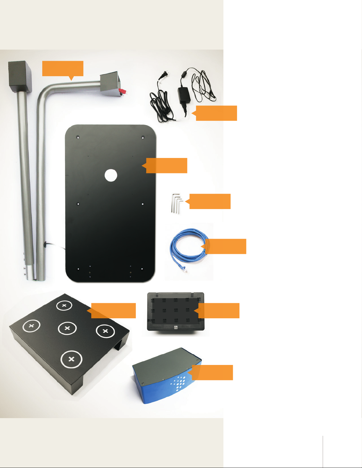
1 Inventory
Pole
Carefully unpack and
familiarize yourself with
everything in the box.
Power cord
Base
Hex wrenches
Calibration box
Ethernet cable
Display
Head
3DimStation Quickstart
Page 4
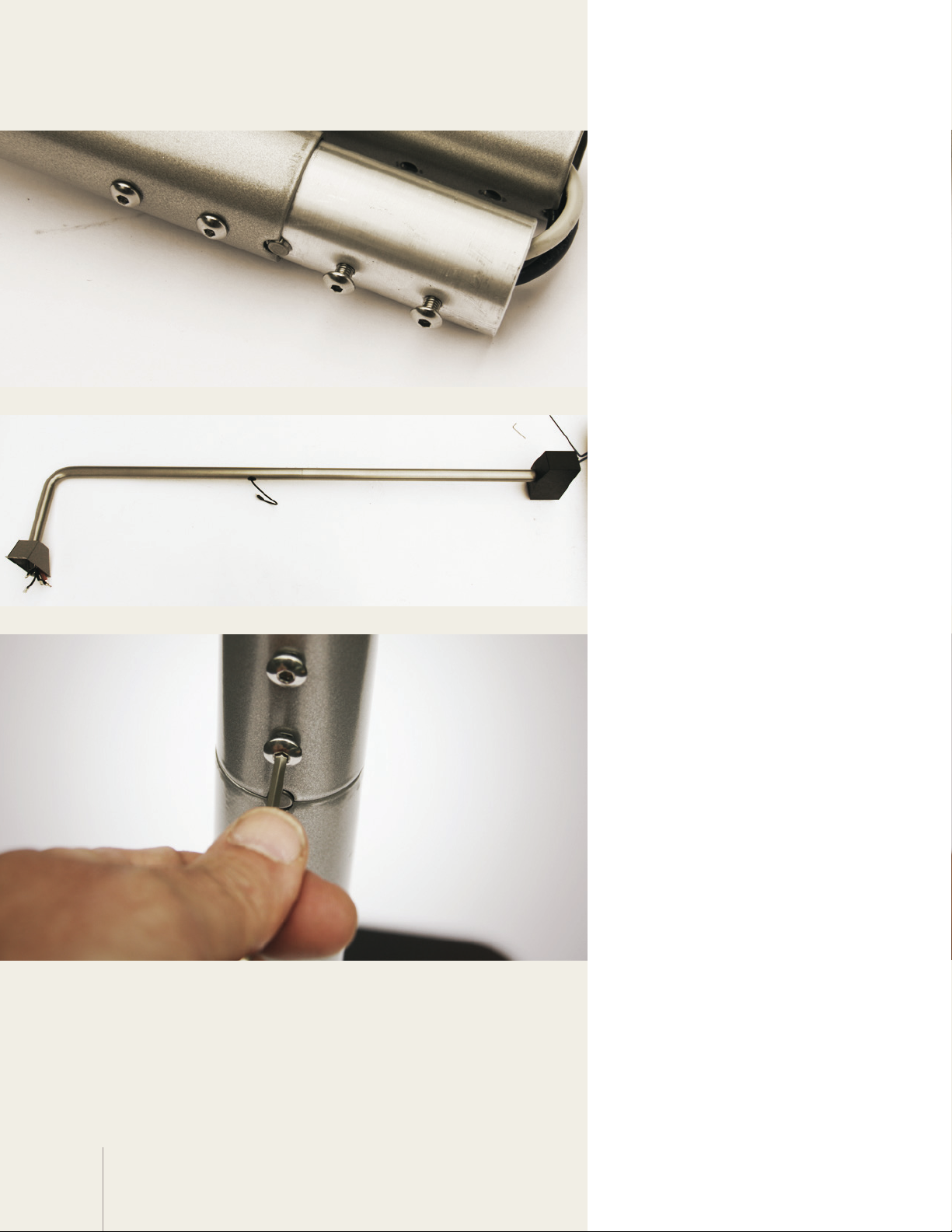
2 Begin pole assembly
Locate the two screws loosely
pre-installed at the pole joint.
Using the appropriate hex
wrench, remove them and set
them aside. Leave the other two
screws in place.
3 Assemble pole
Taking care not to strain the
cables, lay the pole out on the
floor (preferably on a rug or
similar soft surface). Insert the
lower half of the pole into the
upper half.
4 Connect pole halves
Make sure that the poles are
aligned correctly aligned,
using the notch and pin as a
guide. Reinsert and tighten
the bolts you removed in the
previous step.
4
Page 5
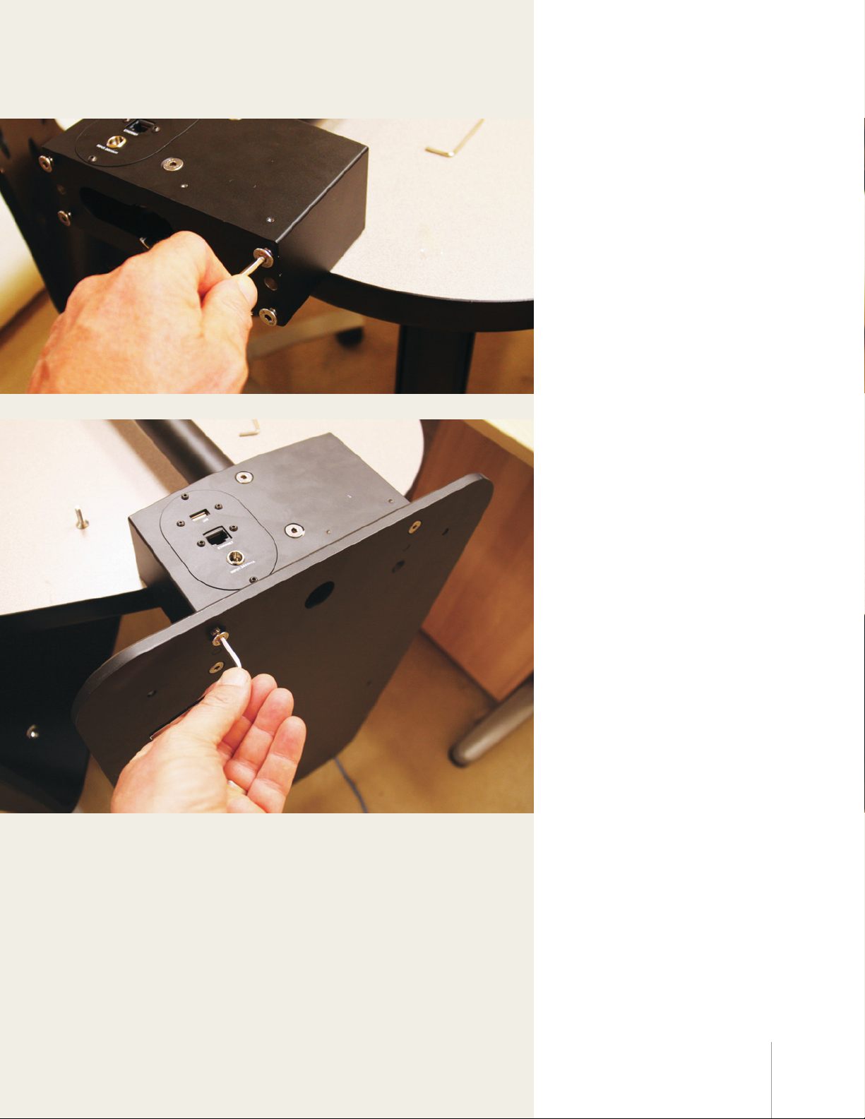
5 Remove power block screws
Lay the pole over a table or the
arms of a chair for this step.
Remove the four bolts that are
pre-installed in the block at the
bottom of the pole.
6 Attach base
With the power block hanging
o the edge of the table, insert
the two pins in the base into the
matching holes in the power
block.
Insert and tighten the four bolts
removed in the previous step.
5DimStation Quickstart
Page 6
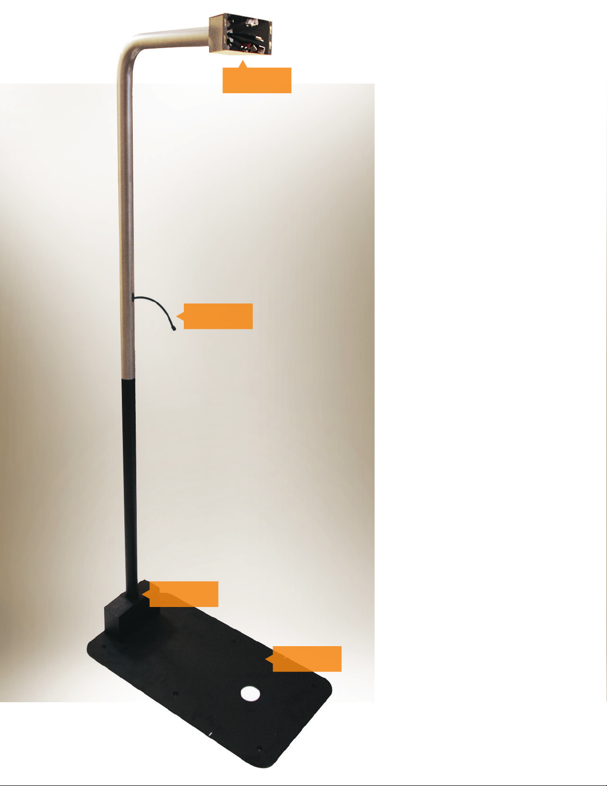
Cable shroud
Display cable
7 Complete pole
Stand the complete, assembled
pole upright.
To make the rest of the
assembly process as simple as
possible, review the names of
the DimStation’s parts at left.
6
Power block
Base
Page 7
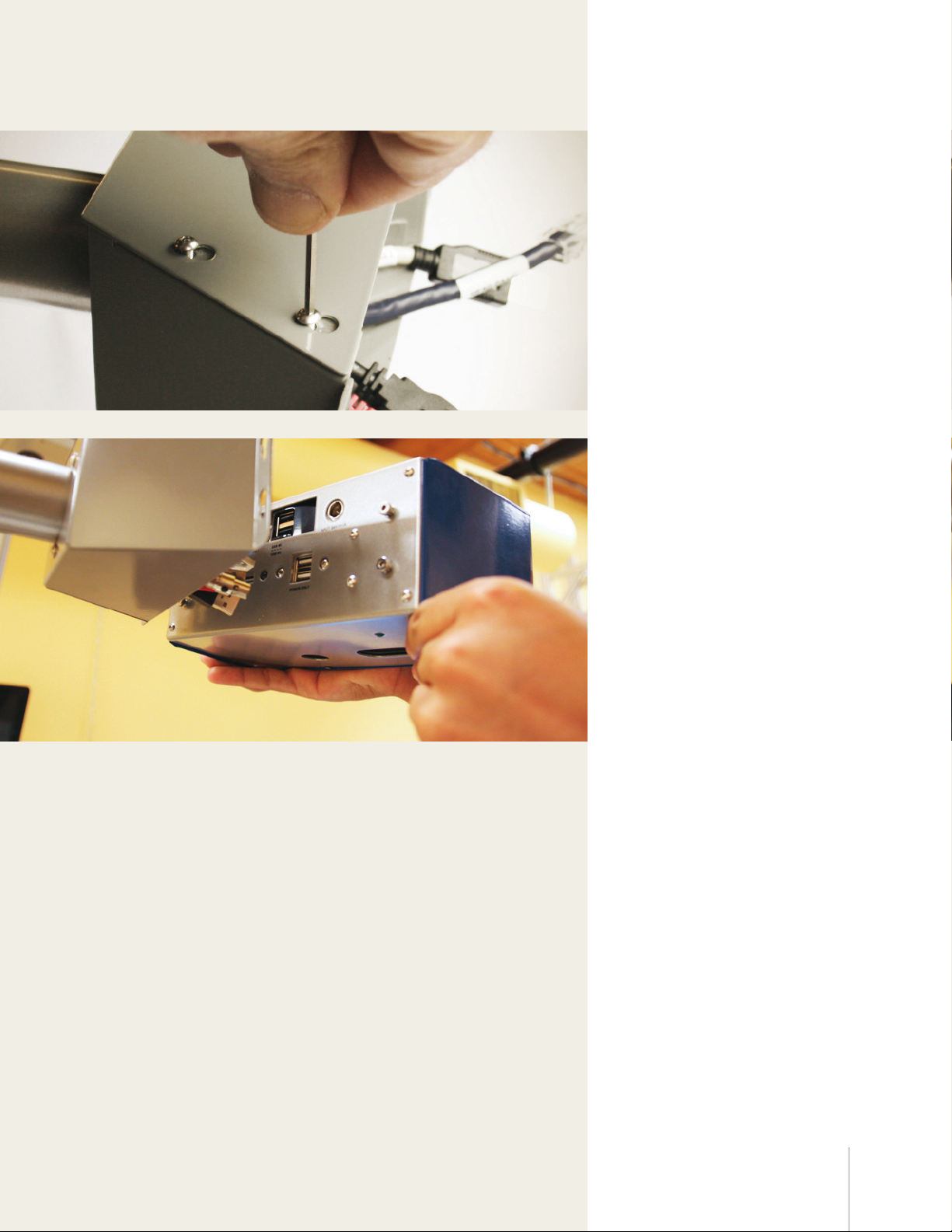
8 Remove cable shroud cover
Loosen the four bolts that
secure the top of the cable
shroud. Do not remove them.
Slide the shroud cover back and
lift it o. Set it aside.
9 Begin attachment of head
Align the head with the cable
shroud at the top of the pole.
It may help to stand on a
stable chair or something of
similar height.
7DimStation Quickstart
Page 8
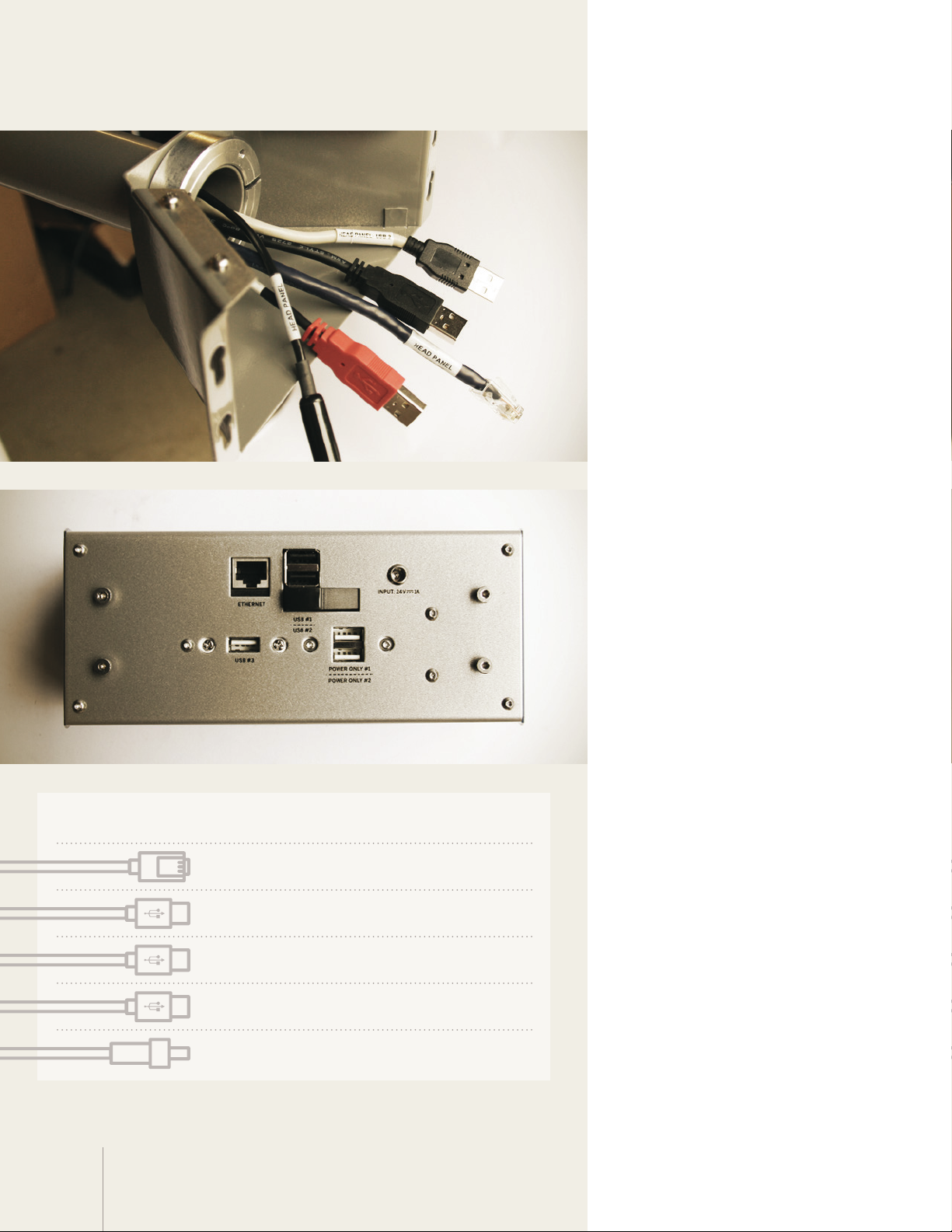
10 Cable names
Note that the cables are labeled.
11 Port names
The ports on the back of the
head are also labeled.
8
Order Cable label Port label
1 Ethernet Ethernet
2 USB 3 USB 3
3 USB 2 USB 2
4 Auxiliary power only Power only 1
5 24 VDC in Input: 24v
12 Attach cables
Use this guide to correctly
connect cables to their ports, in
the listed order.
Page 9
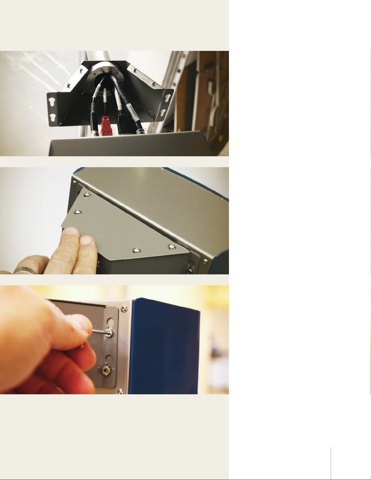
13 Align the head
Gently folding the cables into
the cable shroud, insert the
bolts on the head into the
keyhole slots on the shroud.
Do not tighten them yet.
14 Reattach shroud cover
Put the top back on the shroud
cover. Slide it forward until it
clicks into place, then re-tighten
the fours screws that secure it.
15 Tighten head bolts
Tighten the bolts that attach the
head to the shroud.
9DimStation Quickstart
Page 10
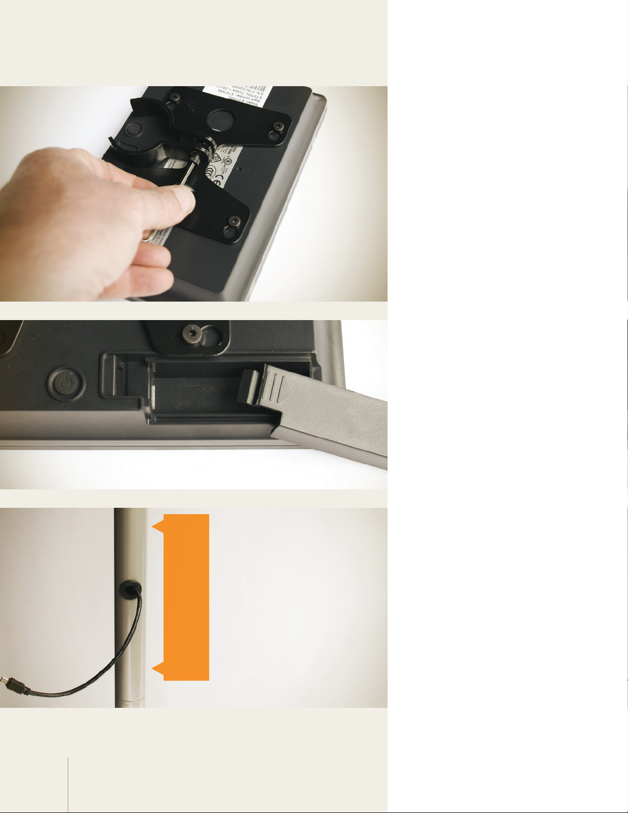
16 Prepare the display
Loosen the bolt that holds the
U-shaped display bracket.
17 Remove cable cover
Remove the cable cover in the
bottom corner on the back of
the display.
±
6 inches
You won’t need this again.
18 Choose display location
The display is usually mounted
just above the display cable
opening.
It’s possible to mount the
display up to 6 inches above or
below the opening – depending
on the size of the items you
dimension, operator height, or
other factors. (You can easily
adjust the display height later.)
10
Page 11
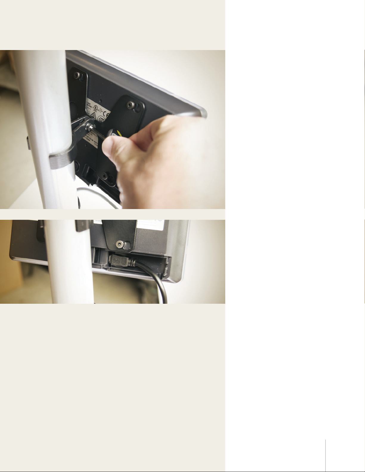
19 Mount the display
Mount the display to the pole
at your chosen location by
re-tightening the bolt on the
U-shaped bracket.
20 Connect the display cable
Attach the display cable to the
mini-USB port located where
you removed the cable cover in
a previous step.
Next, remove the overlay that
protects the display screen.
11DimStation Quickstart
Page 12
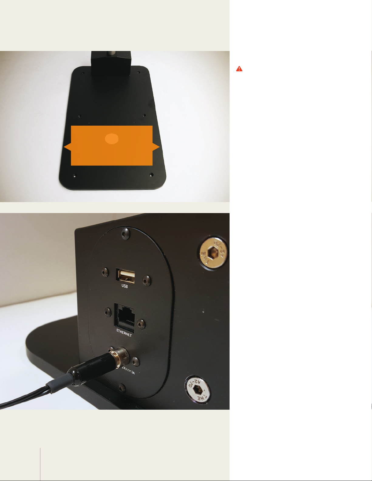
Center the scale
on the engraved lines
on the base
19 Place a scale
If you’re not using a scale,
skip this step.
If you’re using a scale, place it
on DimStation’s base. Center it
from side to side.
To locate your scale front-toback, find the small groove
engraved on both edges of
the base. Use this as the
front-to-back centering point
for your scale.
20 Attach the power cable
Attach the DimStation’s power
cable to the port labeled
“In put 24v.”
The other ports are used in
advanced configurations
covered in additional
documentation.
12
Page 13
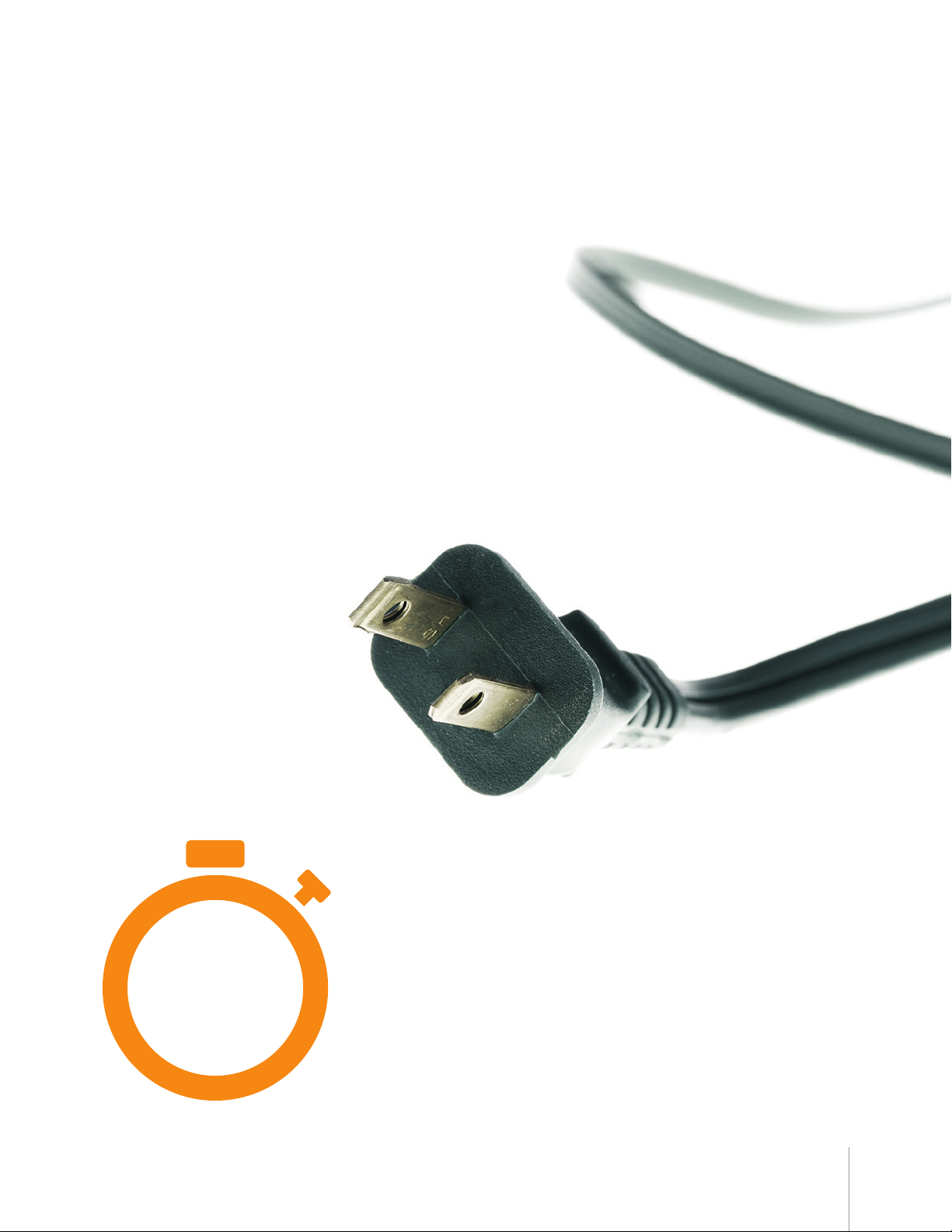
Your DimStation is now ready
to be plugged in. When it is, the
software setup process will
begin automatically.
Don’t plug in your DimStation
unless you have a few minutes to
complete all of the setup steps.
5
minutes
13DimStation Quickstart
Page 14
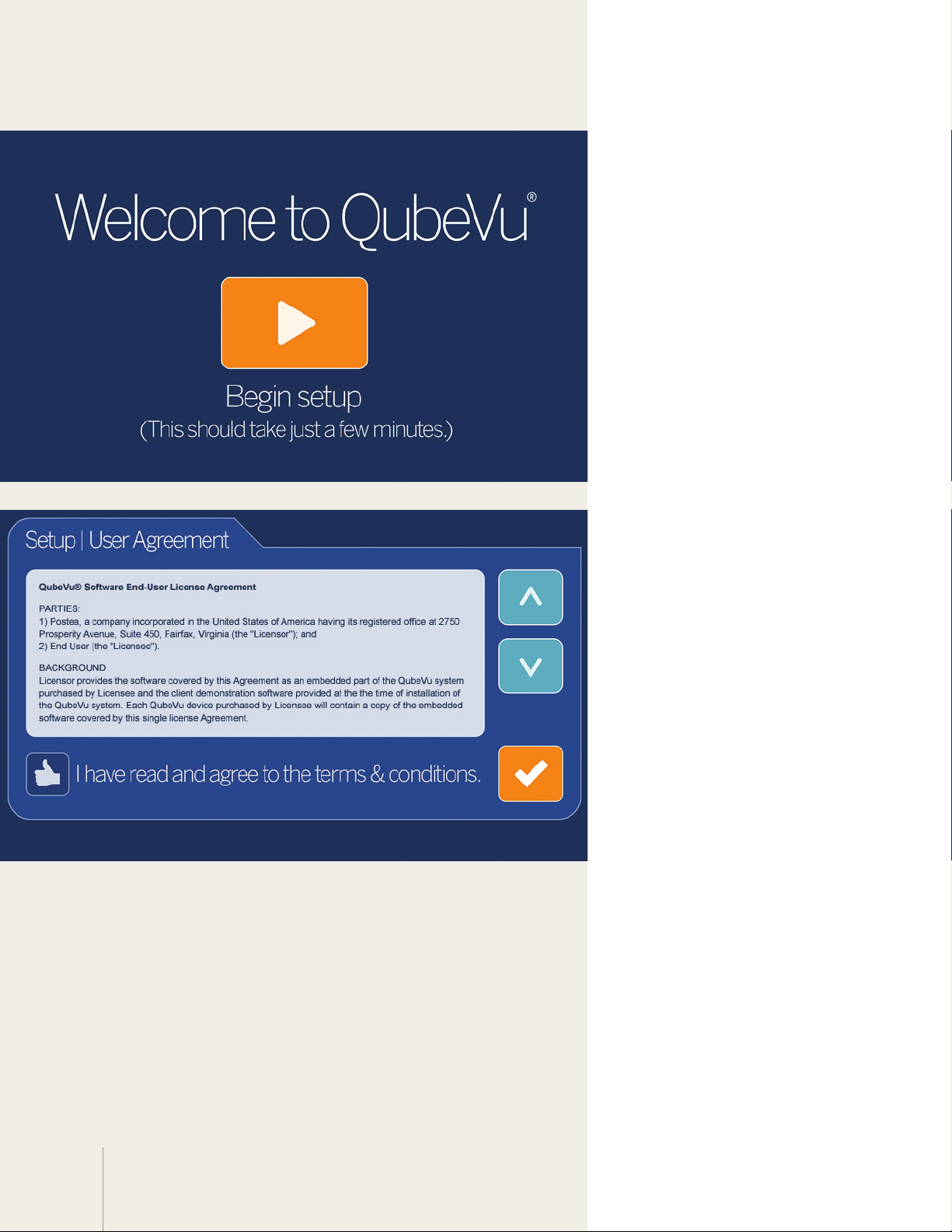
1 Initiate setup
When you start your
DimStation for the first time,
the setup wizard will launch
automatically. Touch the arrow
button to begin setup.
2 Accept the User Agreement
Review the End User License
Agreement (EULA) by using the
up and down scroll buttons on
the right hand side.
Touch the thumbs up button
to confirm you have read and
accept the EULA terms and
conditions. You will not be able
to continue until you do so.
Touch the checkmark to
continue.
14
Page 15
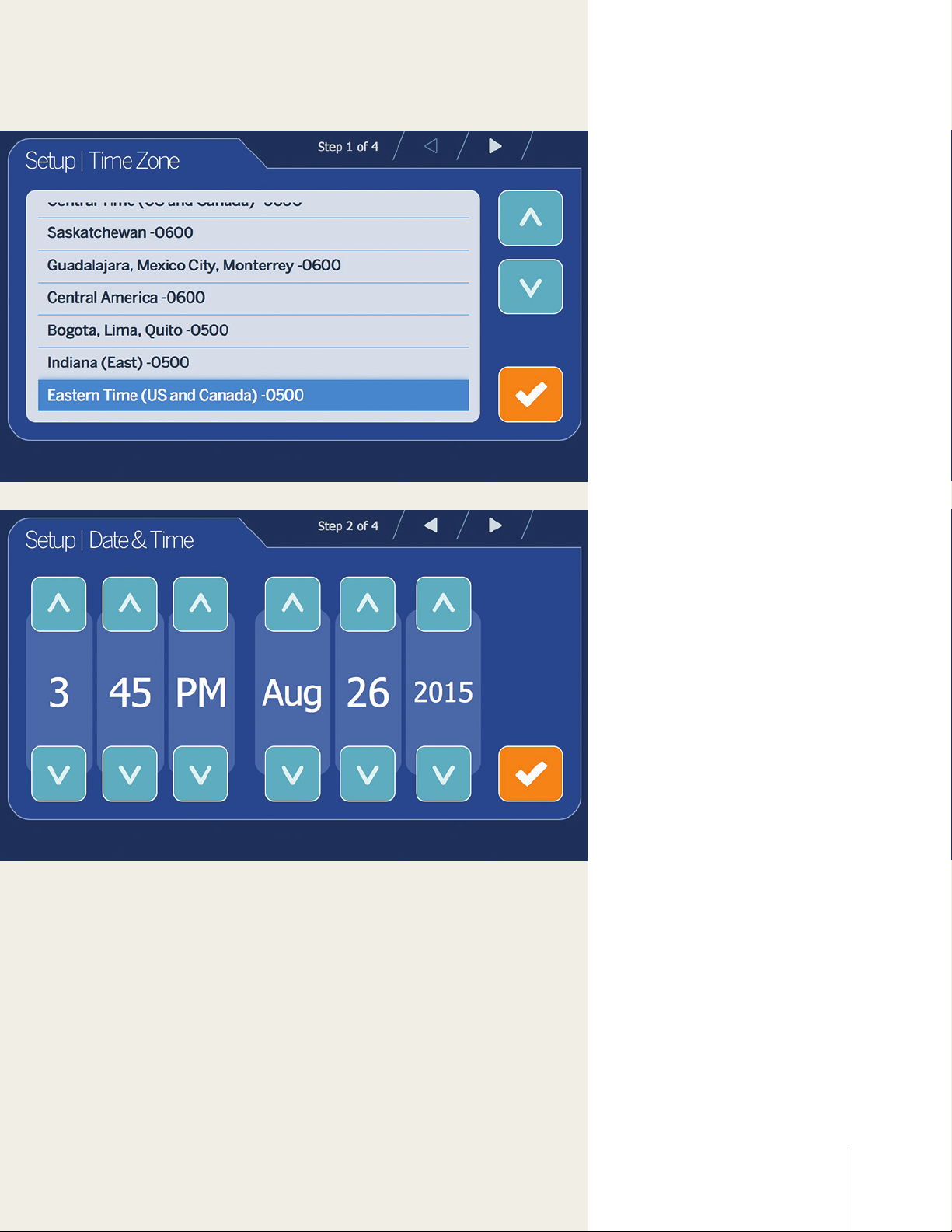
3 Set your time zone
Select your time zone, and
then touch the checkmark to
continue.
4 Adjust the date and time
Adjust the date and time if
necessary, and then touch the
checkmark to continue.
15DimStation Quickstart
Page 16
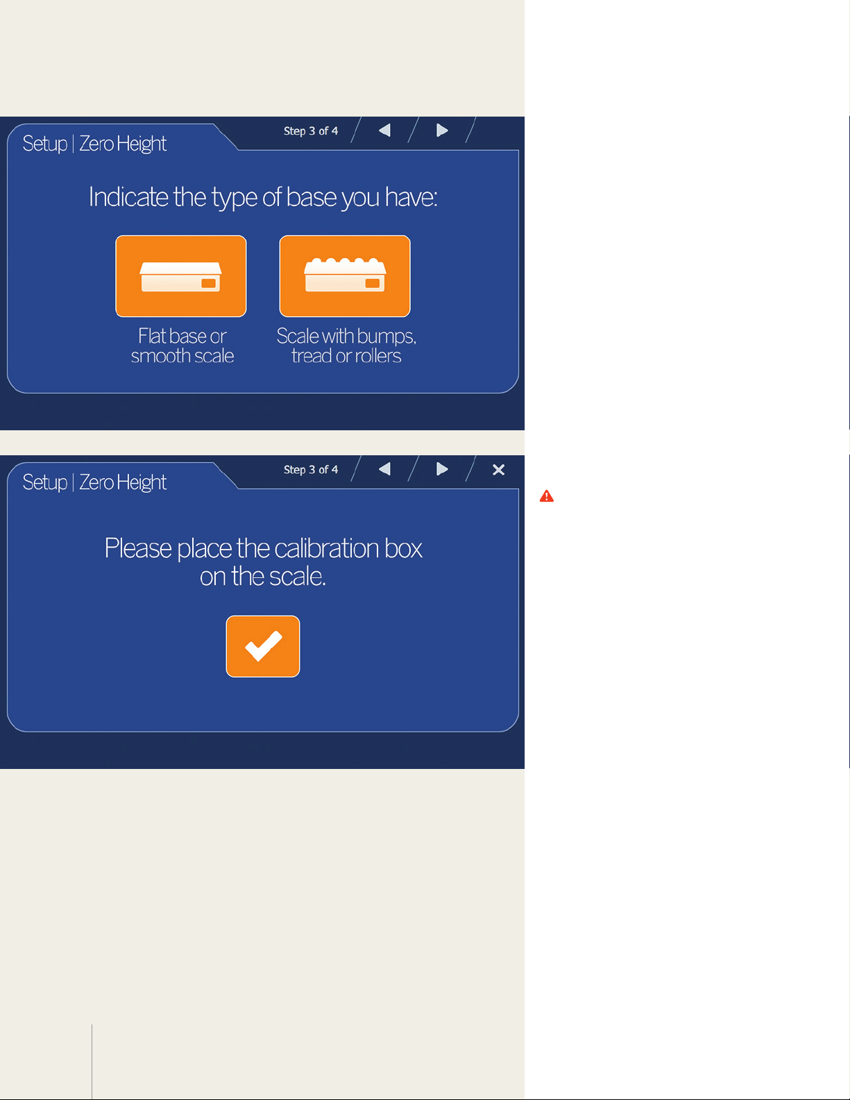
5 Calibrate Zero Height
Zero Height calibration allows
DimStation to calculate the
distance between the scan
head and the base. The process
diers depending on whether
the base is flat or uneven.
If your base is a smooth-topped
scale or the DimStation base,
touch the left button.
If your base is a scale with an
uneven surface (such as rollers),
touch the right button.
6 Zero Height/Uneven surface
If you have a smooth-topped
scale or base, skip this step.
If you indicated that your base
is an uneven scale, you need to
take the extra step of placing
the calibration box on top
of the scale. Then touch the
checkmark to continue.
16
Page 17
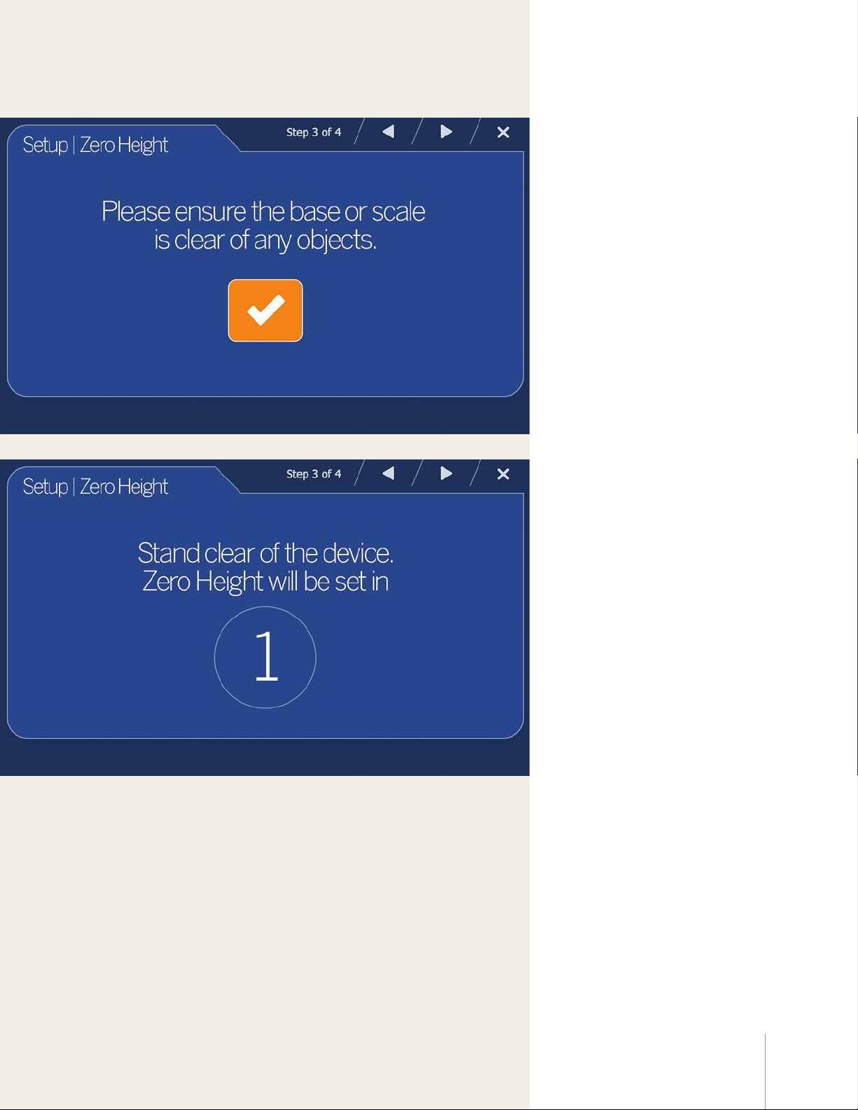
7 Zero Height continued
It is important to keep
DimStation’s base clear and
unobstructed during zero
height calibration, so that it can
set Zero Height accurately.
8 Zero Height continued
Please stand clear before the
countdown completes.
17DimStation Quickstart
Page 18
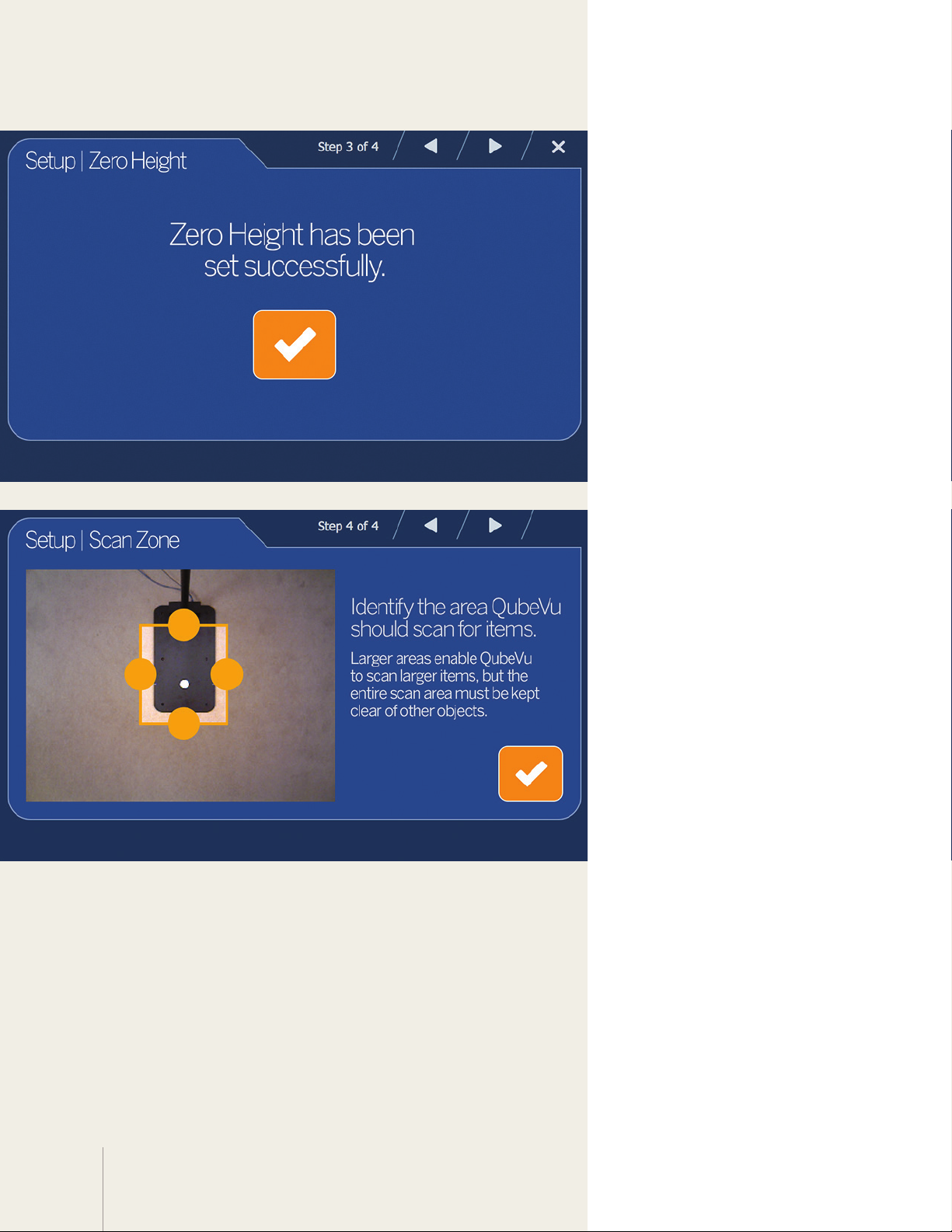
9 Zero Height continued
Zero height has been set.
If you used the calibration
object, remove it from the
base. Touch the checkmark to
continue.
10 Set the Scan Zone
The Scan Zone is the area in
which DimStation looks for
and dimensions items. For
best performance, adjust this
to cover the largest area
possible that can be used for
scanning items and kept clear
of all other objects.
18
Adjust the scan area by
dragging each of the four
touch points. Then touch the
checkmark to continue.
Page 19
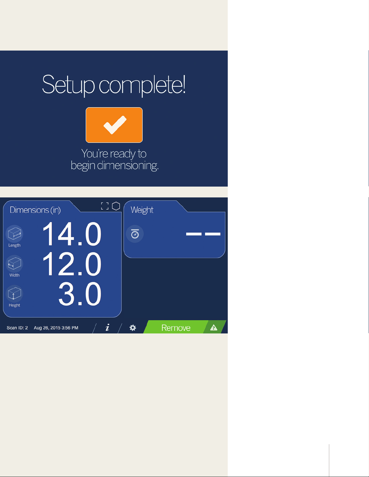
11 Complete setup
Touch the checkmark to begin
using your QubeVu DimStation.
12 Confirm calibration
Test whether your DimStation
is properly calibrated by placing
the calibration object on the
base or scale and checking the
displayed dimensions.
Dimensions should be:
Length: 14.0 inches
Width: 12.0 inches
Height: 3.0 inches
19DimStation Quickstart
Page 20

Congratulations. Your QubeVu
DimStation is ready to use!
• Retain QubeVu packaging. When
transporting your unit, always
disassemble and pack it in its
original packaging.
Please keep these important
precautions in mind when using
your new DimStation.
Failure to adhere to them will
invalidate your warranty, and
resulting damage may lead to
repair or replacement charges.
• Use only supplied power adapter.
Never short-circuit the power
adapter or the QubeVu device.
• Keep dry.
• Operate between 5 and 40ºC.
• Never remove QubeVu’s head
cover, or the electrical connection
panels at the base of the pole
assembly.
• Never modify or attempt to
repair your unit. Service must
be performed only by Postea
personnel.
• Handle cables and cable
connectors with care. Never use
damaged power cords and plugs
or loose electrical sockets, or touch
the power cord with wet hands.
• Ensure that the base plate, pole
assembly and head unit are
all securely attached before
attempting to move your unit.
• Never lift QubeVu by grasping only
the pole assembly; always ensure
that both sections of the pole
assembly and the base plate are
supported.
• Never drop or allow an impact to
QubeVu’s head.
• Mount on a flat surface.
• Never use QubeVu for anything
other than its intended purpose.
20
Page 21

Advanced configuration with
QubeVu Manager
QubeVu Manager is an optional set of software tools provided to enable advanced configuration. They are not
needed in most cases. They are recommended for use only by a technical systems administrator.
This introduction is not intended as a replacement for complete documentation. Please refer to the QubeVu
Manager Guide for a complete guide to the tools. The latest version of the Manager Guide, along with all other
product documentation, can be downloaded from Postea at postea.com/downloads.
Define QubeVu on your Network
QubeVu Manager is accessed via QubeVu’s IP address over a wired Ethernet connection. To access the tools your
QubeVu must be defined on your network.
QubeVu can be installed as a network device and can be configured with a static IP address or using DHCP. Talk to
your network administrator to determine the best approach for your enterprise network.
QubeVu is shipped with a dual IP configuration. The network interface will lease an IP address from any available
DHCP server. However, it also has a fixed, fail-safe IP address of 169.254.1.1. If your prefer to use DHCP, your
network administrator can advise you as to the IP address leased by QubeVu.
Configure PC network settings to connect to QubeVu on 169.254.1.1
• Connect QubeVu to a computer using a standard Ethernet cable
• Configure your computer’s Ethernet interface with an IP address of 169.254.1.10.
Consult with your network administrator if you are unsure how to change your computer’s IP address.
Verify connectivity
• Verify that you can communicate with QubeVu from your computer.
• Use the “ping” command to confirm connectivity.
• ping 169.254.1.1.
If the ping command does not show QubeVu is responding this may be due to an issue with your network
configuration. Make sure that wireless networking is turned o and then try the ping command again. If this is still
unsuccessful contact your network administrator for further assistance.
Access QubeVu Manager
To view the QubeVu Manager home page, open an Internet browser and enter http://169.254.1.1. If you are using
DHCP, remember to replace 169.254.1.1 with the IP address provided by your network administrator.
The default credentials for QubeVu Manager are:
Username: admin
Password: password
21DimStation Quickstart
Page 22

©2015 Pos tea Inc. Al l rights re served . QubeVu and Di mStation a re registe red trade marks of Pos tea.
another innovation by
222 Third Street
Cambridge, MA 02142 USA
www.postea.com
 Loading...