

POSTBERG+Co measuringSYSTEM MA-Di Operating Instructions Manual

measuringSYSTEM
MA-Di
OPERATING INSTRUCTIONS
COMPRESSED AIR AT ITS BEST
Postberg + Co. oers an allround range around the
energy-ecient use of compressed air in industry
From eciency consulting to customized product development of measuring and
sensor technology – also customer-specific as OEM – up to professional support on
all service and outsourcing levels – Postberg + Co. oers you compressed air
eciency packaged under one roof.
Please read these Operating Instructions before you start up the
measuringSYSTEM. These Operating Instructions must be kept at
a place that is accessible to all users at any time.
NOTES ON THE OPERATING INSTRUCTIONS
Notes
This arrow highlights special issues that are to be observed
during operation.
WARNING
This symbol marks instructions where the failure to follow them
will pose a risk to the health and life of persons.
CAUTION
This symbol draws your attention to instructions where the failure
to follow them exactly may lead to damage or destruction of the
measuring system.
Reference
This symbol makes a reference to further information in other
manuals, chapters or sections.
All rights and changes reserved. Any copying, processing and dissemination of this document in whole or in extracts is only
permitted if a written approval from Postberg + Co. GmbH has been obtained in advance.
Copyright
2
©
by Postberg + Co. GmbH, Emilienstr. 37, D-34121 Kassel, represented by Dr. C. Postberg and P. Otto. [Imprint]

MA-Di
V 1.4 KW
valid from 1018
Welcome to Postberg + Co.
Your product: MA-Di
CONTENTS
1 General 4
1.1 Incoming goods inspection, transport and storage 4
2 Safety precautions 5
2.1 Intended use 5
2.2 Installation, start-up and operation 6
2.3 Disclaimer 7
3 Functions and applications | Scope of supplies 8
3.1 Electrical sensor Direct-i 9
3.2 Measuring armature of brass 11
3.3 PB+CO®lock-blind plug 11
3.4 ISO Calibration Points 12
4 Technical Data 12
4.1 Thermal mass flow sensor 12
4.2 Accessories 13
5 Installation 15
5.1 Identifying the installation position 15
5.2 Linear dimension of the measuringSYSTEM 15
5.3 Installation position 16
5.4 Required measuring distance 17
5.5 Flow direction 18
5.6 Installation of the sensor in the measuring armature 18
5.7 Sensor exchange 19
5.8 Electrical connections 20
6 Operation 22
6.1 Operating and display elements 22
6.2 Operating modes 24
7 Menu 25
7.1 Menu Overview 25
7.2 Menu explanation 26
8 Programming + parameter setting 27
8.1 Programming 27
8.2 Parameter setting scenarios 29
8.2.1 Settings for flow rate monitoring 29
8.2.2 Settings for consumption rate monitoring 30
8.2.3 Settings for temperature monitoring 32
8.2.4 User settings (optional) 33
8.2.5 Service functions 35
8.2.6 Impulse setting 36
9 Maintenance 39
9.1 Error messages 39
9.2 Sensor cleaning 39
9.3 Calibration 40
10 Troubleshooting 41
10.1 Replacement of defective parts 41
10.2 Replacement of O-ring and sealing ring 41
10.3 Returning sensors 41
10.4 Disposal 41
Notes 42
COMPRESSED AIR AT ITS BEST
3

1 General
1 GENERAL
1.1 Incoming goods inspection, transport and storage
• Please make sure that the packaging is undamaged!
Please notify any damage on the packaging to your supplier.
Hold on to the damaged packaging until clarification is achieved.
• Please make sure that the content is undamaged!
Please notify any damage on the packaging to your supplier.
Keep the damaged item until clarification is achieved.
• Check the scope of supplies against the delivery documents and
your order for completeness.
• For storage and transport, the device shall be packed in an impact-
resistant manner and protected against moisture.
The original packaging oers optimum protection. In addition, the
permissible ambient conditions shall be ensured ( Section 4
Technical Data p. 12).
• In the case of queries, please contact your supplier or his central
sales oce.
4

2 Safety precautions
Any other use than the one described does not ensure the
safety of persons and the entire measuring device and is not
permitted.
The manufacturer shall not be liable for damage that occurs as a
result of improper or not intended use or installation.
To avoid damage to the devices or health risks, no manipulations
with tools on the measuring devices are allowed unless they are
expressly described in these Operating Instructions.
MA-Di
2 SAFETY PRECAUTIONS
Please read these Operating Instructions before you start up the
measuringSYSTEM. These Operating Instructions must be kept at
a place that is accessible to all users at any time.
2.1 Intended use
The measuringSYSTEM is exclusively intended for use in piping line
systems for operating compressed air, unless its permission for the
use with other gases is expressly stated on the calibration certificate.
Due to its design, it can be operated in pressure systems up to PN 16.
CAUTION
The measuringSYSTEM must not be operated or assembled and dis-
mantled under the ambient conditions indicated in the technical data.
Otherwise, measurement inaccuracies occur or device failures cannot
be excluded.
To ensure the safety of the user and the function of the devices, the
start-up steps, inspections and maintenance activities recommended
by the manufacturer shall be observed and conducted.
For reasons of clarity, these Operating Instructions do not include the
complete detail information. Should you wish to obtain further information or should any special problems occur which are not described
in detail in these Operating Instructions, the required information can
be requested directly from the manufacturer.
COMPRESSED AIR AT ITS BEST
5

2 Safety precautions
2.2 Installation, start-up and operation
The measuringSYSTEM was manufactured and tested for reliable
operation and left the factory in a fault-free safe condition.
As user, you shall be responsible for compliance with all applicable
safety regulations, e.g.:
• Installation regulations
• Local standards and regulations.
The manufacturer has taken every eort to ensure safe operation.
The user has to make sure that the devices are placed and installed in
such a way that their safe use is not aected.
The devices were factory-tested and delivered in reliable operating
condition. The present Operating Instructions include information and
warnings that must be followed by the user to enable safe operation.
• Installation, start-up, operation and maintenance of the measuring
device may only be performed by trained and qualified personnel.
This qualified personnel must be authorised by the plant operator to
perform the described activities.
• The qualified personnel must have read and understood these
Operating Instructions and must follow the mentioned instructions.
• Check before starting up of the overall measuring point if all connections
have been made correctly.
• Any damaged products must not be started up and shall be safe-
guarded against unintended start-up. The damaged product must be
marked as defective.
• Any failure on the measuring point may only be remedied by authorised
and trained personnel.
• If failures cannot be remedied, the products must be taken out of
operation and safeguarded against unintended start-up.
• Any repairs which are not described in these Operating Instructions
may only be performed directly by the manufacturer or the service
organisation.
6

2 Safety precautions
MA-Di
2.3 Disclaimer
In general, the manufacturer and his vicarious agents shall only be liable
in the case of intent or gross negligence. The scope of liability shall be
limited to the value of the relevant order placed to the manufacturer.
The manufacturer shall not be liable for damage that occurs due to
failure to follow the safety instructions, non-compliance with these
Operating Instructions or the operating conditions. Any consequential
damages shall be excluded from the liability.
COMPRESSED AIR AT ITS BEST
7
3 Functions and applications | Scope of supplies
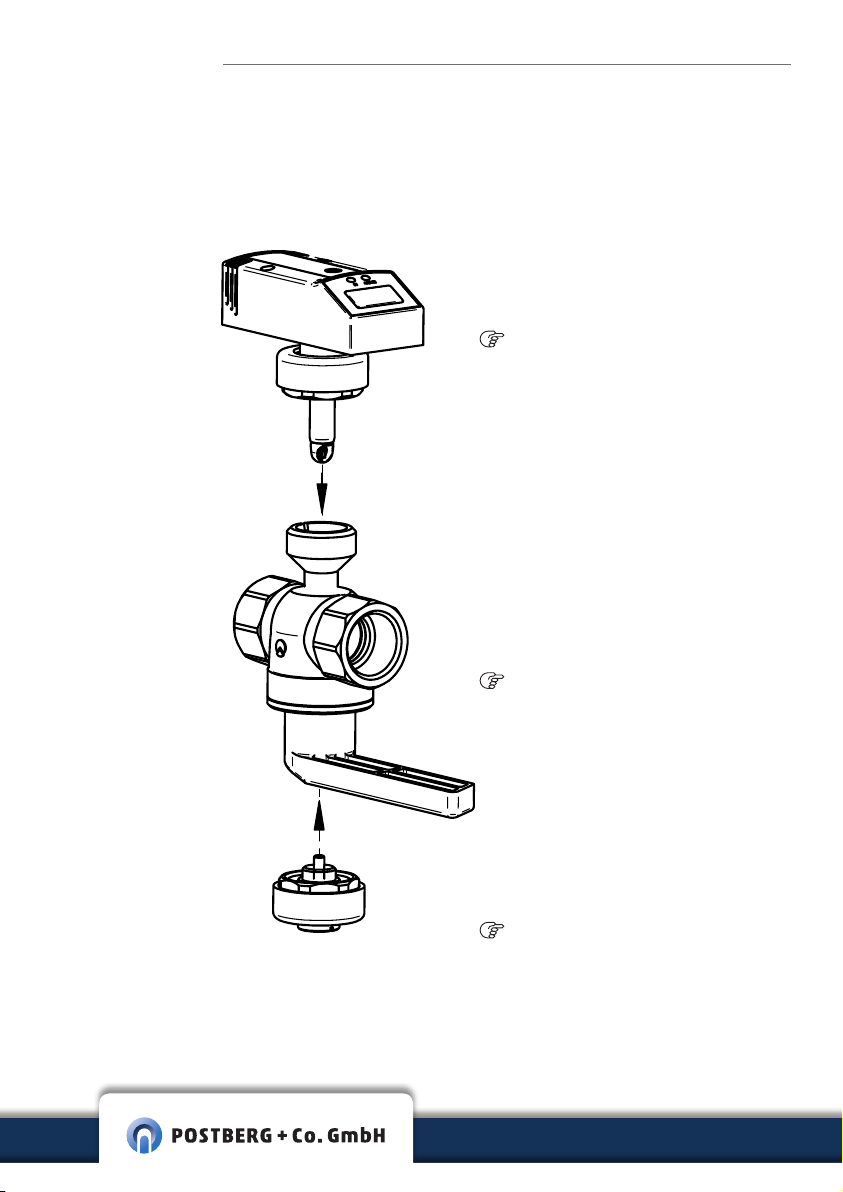
3 FUNCTIONS AND APPLICATIONS |
SCOPE OF SUPPLIES
Components List
Sensor unit
Direct-i
3.1 | p. 9
Measuring armature
brass
3.2 | p. 11
Furthermore, the following is included in the scope of supplies:
• Calibration certificate according to ISO/IEC 17025
• Optional: Test badge for recalibration on the device
8
PB+CO®lock blind plug
3.3 | p. 11

3 Functions and applications | Scope of supplies
MA-Di
3.1 Electrical sensor Direct-i
With the aid of the calorimetric measuring principle, the sensor detects
the standard volume flow of the operational compressed air.
To this end, the standard volume flow is calculated on the basis of DIN
ISO 2533 (1013.25 mbar, 15 °C and 0 % relative humidity) if not indicated
otherwise in the calibration certificate. The unit of this is Nm³/h or Nl/min.
Please observe the General Operating Conditions of compressed
air systems. The air quality of the operational compressed air has the
following impact on the measuring accuracy:
Quality grades as per ISO 8573-1
Particles – moisture - oil
1-4-1 ± (3 % of measured value + 0.3 %
3-4-4 ± (6 % of measured value + 0.6 %
Measuring failure
of end value of measuring range)
of end value of measuring range)
Measuring signals
The instrument shows the current process values on display.
It generates 2 output signals according to the parameter assignment.
• Current flow rate
• Current consumption rate (impulse output and totalizer)
Display
• A Current flow rate in Nm³/h or Nl/min
• Current consumption rate in Nm³
• Current mean velocity in Nm/s
• Current media temperature in °C
• Switching conditions of the relevant outputs
COMPRESSED AIR AT ITS BEST
9
The compressed air meter may be used for volume flow measurements of operating compressed air up to an overpressure of
16 bar.
3 Functions and applications | Scope of supplies
Sensor output 1
• Switching signal as limit value for flow rate or flow speed, hysteresis or
window function as normally open or normally closed contact.
• Quantity control by preselection meter.
Sensor output 2
• Switching signal as limit value for flow rate, flow speed or temperature,
hysteresis or window function as normally open or normally closed contact.
• Analog signal (4...20 mA) for corresponding volume flow, flow speed or
temperature.
Relative measuring range (%)
Measuring range Detection range / display range
0.33 % (0.4 %) - 100 % 0 % - 120 %
The absolute measuring range is depending on the nominal width (see
table below).
Absolute measuring range
WARNING
Nominal width Measuring range Detection /
DN 15 0.33-100 m³/h 0-120 m³/h
DN 20 0.5-150 m³/h 0-180 m³/h
DN 25 0.8-250 m³/h 0-300 m³/h
DN 32 1.3-400 m³/h 0-480 m³/h
DN 40 2.1-620 m³/h 0-744 m³/h
DN 50 3.3-1000 m³/h 0-1200 m³/h
Data according to DIN ISO 2533 (15 °C, 1013 mbar and 0 % rel. humidity).
10
display range
The measuring armature must not be dismantled (function loss)
and can be used up to an overpressure of max. 16 bar.
3 Functions and applications | Scope of supplies
MA-Di
3.2 Measuring armature of brass
The measuring armature patented by Postberg + Co. is equipped with
an integrated safety ball valve that accommodates the sensor unit. As a
result, it enables the shut-o of the pressure line at any time and an easy
sensor replacement.
It is possible to de-pressurize areas of the pressure network which are
currently not in operation or not needed. As a result, leakage losses on
the consumers are excluded during downtimes. The measuring armature
is designed for nominal pipe widths of DN 15 to DN 50.
WARNING
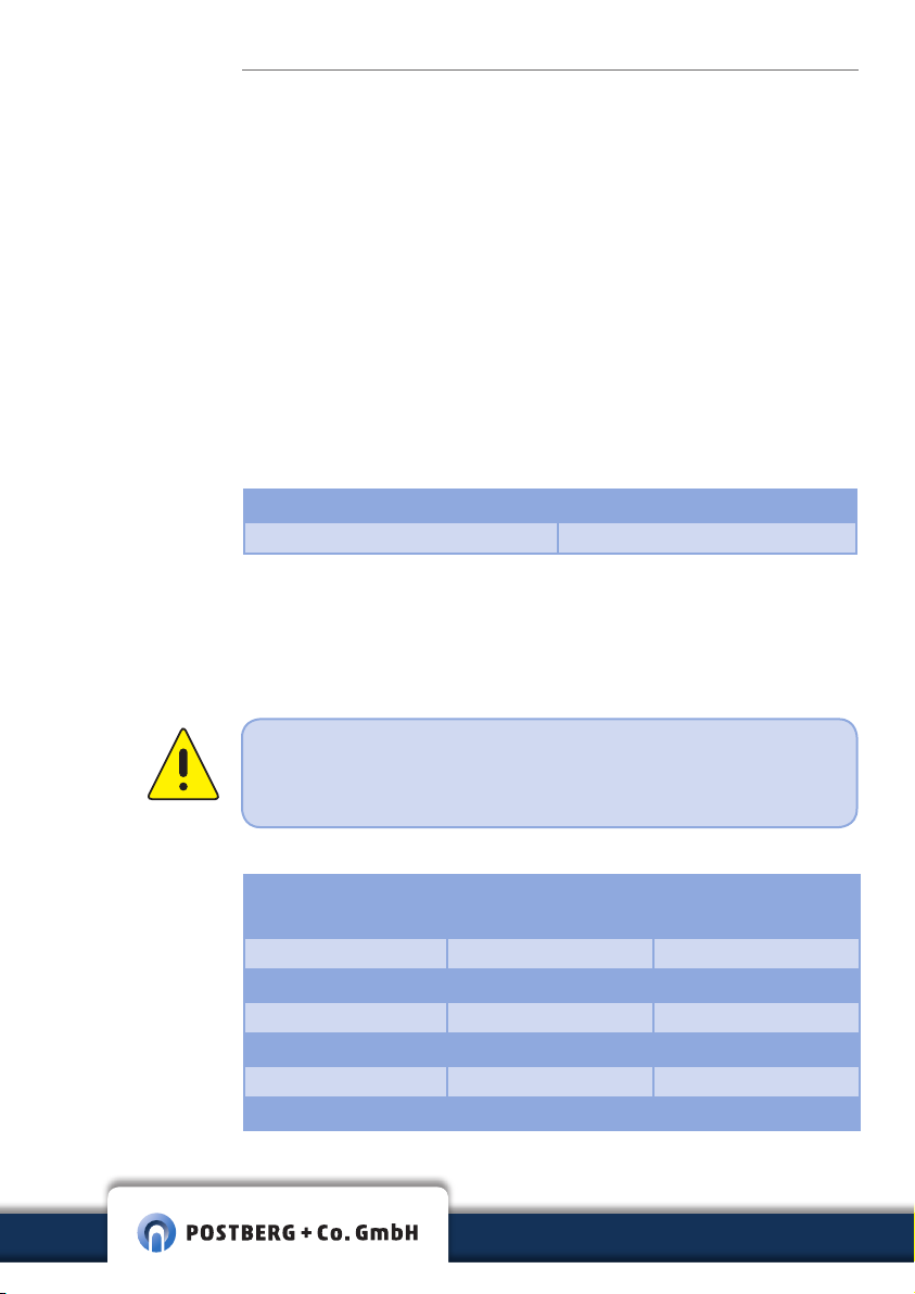
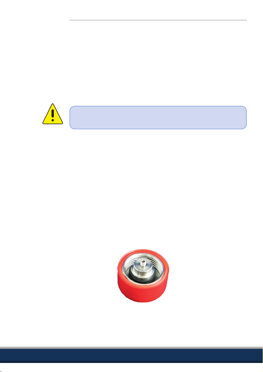
3.3 PB+CO®lock-blind plug
The PB+CO®lock-blind plug protects the measuring point interface while
the sensor is not installed. The PB+CO®lock provides a metallic seal and is
equipped with a redundant O-ring sealing.
A significant benefit compared to the simple blind plug is that the
enclosed compressed air may be released without any risk during an
(unintended) dismantling under pressure. When turning the cap screw,
a sucient number of threads remains to prevent a “shooting o”.
COMPRESSED AIR AT ITS BEST
11

4 Technical data
3.4 ISO Calibration Points
The MA-Di measuringSYSTEM has been calibrated to your nominal width
before delivery. At least six measuring points with defined nominal width,
standard temperature and pressure are parameterized, started up on the
test stand and checked regarding the standard volume. The calibration
certificate according to ISO/IEC 17025 is included in the scope of supplies.
Optionally, a test badge is attached to the device.
4 TECHNICAL DATA
4.1 Thermal mass flow sensor
The thermal mass flow sensor for the compressed air volume flow measurement depends on the process pressure and the fluid temperature.
Sensor Thermal, glass-passivated ceramic sensor
Fluids Compressed air, with special calibration also
CO2, N
Accuracy for compressed air quality classes (ISO 8573:
particle-moisture-oil) 1-4-1: ±3 % of measured
value, ±0.3 % of end value for compressed air
quality classes (ISO 8573) 3-4-4: ±6 % of
measured value ±0.6 % of end value
Temperature control ± 2 °C
Reproducibility ±1.5 % of measured value
Display, operation 4-digit alphanumeric display, two operating
buttons, operating menu, 5 x LED green (phys.
units), 1 x LED green (10³), 2 x LED yellow
(switching conditions)
Display units * Nl/min, Nm³/h, Nm/s, Nm³, °C
Measurement dynamics 1:300
Response time < 0.1s
Pressure-resistant Up to 16 bar overpressure
Medium temperature 0 ... + 60 °C (max. 90 % rel. humidity)
Ambient temperature 0 … + 60 °C
Storage temperature -25 …+ 60 °C
Fluid contact V2A (1.4301), ceramic glass-passivated, PEEK,
polyester, Viton, anodized aluminium
Housing materials PBT-GF 20, PC (APEC), Makrolon, V2A (1.4301),
Viton
Degree of protection / IP65 / III
protection class
2
12

Due to its small size, the sensor has a very small surface for attack.
Consequently, the pressure loss can be neglected (typically 1 mbar).
4 Technical data
Electrical connection M12 x 1-plug, capacity up to 250 mA,
short-circuit proof
Voltage supply 19 … 30 VDC, current input < 100 mA
Delay before start 1 s
Notes
* The measuring, display and setting ranges refer to, unless indicated
otherwise in the calibration report of sensor, to the standard volume
flow according to DIN ISO 2533 (15 °C, 1013 mbar and 0 % rel. humidity).
Output signals
Analog output 4…20 mA, measuring range scalable
max. load 500 Ω
Impulse output DN 15 - DN 25: 1 Imp./0.1 Nm³
DN 32 - DN 50: 1 Imp./1 Nm³
Current load capacity 2 x 250 mA, short-circuit proof, protected against
polarity reversal, overload-proof
EMC
IEC 1000/4/2 ESD 4 / 8 kV
IEC 1000/4/3 Hf radiated 10 V/m
IEC 1000/4/4 Burst 2 kV
IEC 1000/4/6 Hf line-bound 10 V
MA-Di
4.2 Accessories
4.2.1 In- and outlet pipe (DN 15–DN 50)
To calculate the inlet pipe needed it is 15x diameter (D) + additional flow
columing section (B) and 5x diameter (D) for the outlet pipe ( 5.4 |
p. 17). They are both made of stainless steel with a male thread to connect
to the existing pipe system.
COMPRESSED AIR AT ITS BEST
13

Please make sure to indicate the certificate no. of the damaged
sensor when ordering a new one. This ensures factoring the
customized measuring conditions while calibrating.
4 Technical data
4.2.2 Connecting line with potential isolation
As accessory, a connecting line with a potential isolation integrated in the
plug is available. The line has a length of 5 m and serves for galvanic isolation between sensor output and connected electronic system. The line
will be delivered with an appropriate connection plug for the mass flow
sensor on one side and open line ends on the other side.
4.2.3 Replacement sensor
The replacement sensor serves as spare part in the case of damage or
loss of the original mass flow sensor.
Notes
4.2.4 Calibration options
• ISO certificate
An ISO certificate of the manufacturer documents six measuring points
incl. measuring conditions.
• Test badge for next recalibration
By request a test badge as a reminder of the annual recalibration can be
fixed to the sensor.
• Sensor parametrization on CO2 and N
At least six measuring points with defined nominal width, standard tem-
perature and pressure for nitrogen or carbon dioxid are parameterized,
started up on the test stand and checked regarding the stand volume.
calibrationSERVICE
Safeguard the measuring quality
and, with this, the implementation of ISO 9001 and ISO 50001
through an annual recalibration –
on request with immersion sensor
to minimize the downtime.
Further support modules p. 43
14
2
 Loading...