

Page 1

Instruction Manual
for
POSP 4x24 / PSO-1
Rifle scopes
1. NTRODUCTION
Before using the scope carefully read this instruction manual.
The scope is equipped with built-in mount that can incorporate three different types of clamps designed to mount on
distinct types of rails. Before attempting to mount the scope learn which type of mount your plate will accept as it is crucial
for proper function of the scope.
The scope is designed with extended eye relief and has a rangefinding capability. Red illuminated reticule will ensure
target acquisition at low light conditions.
As the design constantly being updated the actual scope may slightly differ from this manual.
The scope can be used in a variety of climatic conditions with temperatures ranging from -50°C...+50°C (-50°F…+120°F)
The scope is also sealed against sand and dust as well as filled with Nitrogen to prevent fogging.
2. SPECIFICATIONS
Magnification…………………………………. 4x
Input lens dia………………………………….24 mm
Field of view………………………………….. 6°
Eyerelief………………………………………. 68 mm
Battery type………………………………….. "AA"
Temperature range…………………………. -50° F...120° F
Dimensions………………………………….. 16" x 5.4" x 2.8"
Weight…………………………………………20 oz.
3. INCLUDED EQUIPMENT
3.1 All scope packages must contain items listed under “STANDARD PACKAGE”
3.2 Manufacturer, upon its own discretion or by the customer request might also include items from the “OPTIONAL
ACCESSORIES”
STANDARD ACCESSORIES
Scope w/illuminated reticule – 1
Rubber eyepiece – 1
Manual – 1
Carry case – 1
OPTIONAL ACCESSORIES
Light filters – 1
Mounting plate – 1
Rubber eyepiece – 1
Cold battery pack -- 1
4. GENERAL DESCRIPTION
4.1 Inserting / Replacig the Battery
The scope is quipped with reticule illumination system that uses single 1.5V “AA” battery. To replace battery remove cover
from the battery compartment, by pressing it down and twisting it counter clockwise.
Install new battery keeping the polarity, close the battery compartment.
If reticule looses its brightness over time, replace the battery.
Page 2
1
4.2 Mounting the scope
The scope has a built-in mount that can be equipped with three different types of clamps designed to mount on different
types of rails. Before attempting to mount the scope learn which type of mount your plate will accept as it is crucial for
proper function of the scope, as some mounting clamp are not designed to accept certain types of rails.
PLEASE NOTE, that by "not designed to accept certain types of rails" we mean the configuration of the rail and NOT its
size, as 99.99% of the scopes, if properly adjusted (please see 4.2.1), will fit the bulk majority of the mounting rails found
on AK family of guns. Thus, it might be possible to mount the scope on the gun, you may encounter such problems, as too
much or not enough of eye relief, or the scope won't hold its "zero" if removed. Often you can tell that the scope isn't
designed to fit the rail on your gun by mounting the scope and firing a few shots. If the clamp on your scope doesn't match
the rail, the scope will fall off after the third or fourth shot, no matter how tight it is locked.
To avoid this, you should learn about the three types of Russian rifle scope clamps and which rails should be used with
each type of clamp.
A. Russian Standard Small Arms Mounting System clamp, used on all of the Night Vision Rifle Scopes and
some daylight scopes. This type of mount is universal and will properly fit all types of mounting plates.
B. PSO-1 or Dragunov style mount found on the PSO/POSP rifle scopes. This type of mounting clamp has a
forward placed stopping pin. The clamp moves all the way forward on the rail until the stopping pin comes
to rest at the closed end of the rail. REMEMBER that the scopes with the PSO- type of mounting clamp
will properly fit the plate on your rifle ONLY if the front end of the rail is CLOSED. This won't allow the
scope to come off at the other end of the rail and the scope will always retain its "zero".
C. Saiga/AK type of mounting clamp has the rear placed stopping pin and designed to fit mounting plates
found on AK, Saiga, and Vepr rifles. The clamp has to slide forward on the rail until it stops as the pin
comes against the back (right) end of the mounting plate. REMEMBER that the scopes with the AK/Saiga
type of mounting clamp will properly fit the plate on your rifle ONLY if the plate has a CLOSED right end
of the rail.
To mount the scope release the locking lever and align the rail on your gun with mounting clamp, slide the scope forward
on the rail until it stops. Close the locking clamp. If the scope can not slide along the rail or the locking lever can not be
closed with reasonable force the mounting clamp has to be adjusted. Adjustment might be needed if the scope sits too
loosely.
4.2.1 Locking clamp adjustment
LOCKING CLAMP ADJUSTMENT REQUIRES NO SPECIAL TOOLS OR SKILLS, PLEASE READ THE
INTSRUCTIONS BELLOW
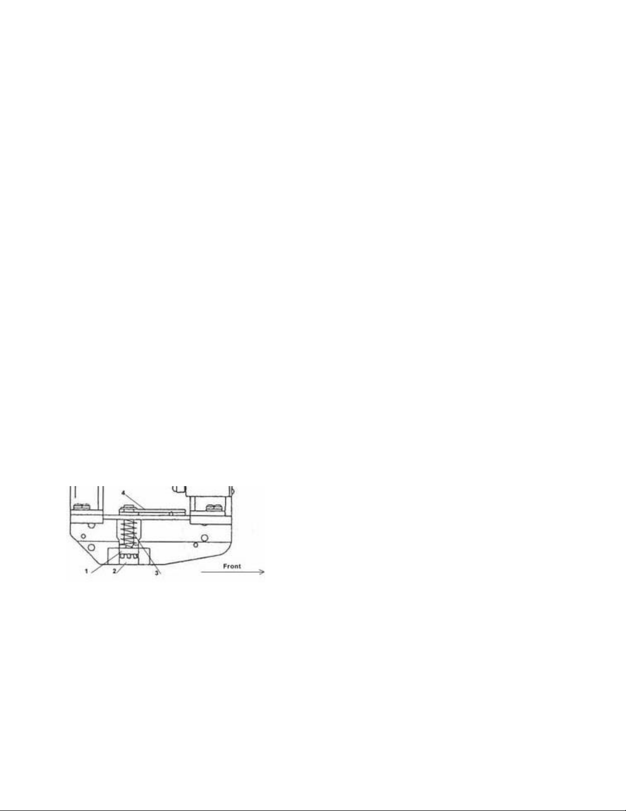
Locate the locking clamp assembly, (see picture on the left). The
locking assembly consists out of the locking rail (1) round adjustment
nut (2), spring (3) and the locking lever (4). The round nut controls the
tightness of the locking mechanism. To adjust the clamp, turn the
scope up side down, presses down and hold the locking rail (1) with
the thumb of your left hand. With your right hand adjust the nut (2) by
turning it. Turn the nut clockwise to tighten the mount and
counterclockwise to loosen it up.
5. Sighting and Zeroing the Scope
Tightly secure the gun at the firing station using sandbags or special sighting rack to avoid shooter related inaccuracy.
Using your iron sights fire 4-5 shot group. Without moving the rifle look through the scope and determine average point of
impact (API). One or two shot may deviate, this it is normal, disregard those shots. Make necessary adjustments to the
scope using the windage and the elevation turrets. If during sighting process you run out of adjustment room on either the
windage or the elevation turret do the following: Loosen two screws located on the top of the turret and turn the black, top
part of the turret without touching the silver cam. Once the reticule is in the required position stop turning the top part of
the turret and now move the silver cam somewhere to the middle of the scale relative to the dash mark on the scope. After
adjusting the reticule, fire a few more control shots and compare the API with the previous group of shots if the result are
the same the scope is sighted. Now you will have to put the elevation cam to “zero” position which in some cases may not
be the actual “0” on the elevation cam. Please refer to the table bellow to see where the actual “zero” is on your scope.
Page 3

2
To adjust the elevation cam to “zero” position loosen the two screws on the top of the turret and carefully move the cam
to proper position. Tighten the screws.
5.1 Elevation turret
There are at least two different elevation turrets that come with POSP/PO/PSO type scopes. One has an uneven scale
numbered from 0 to 10 with different number of clicks between the numbers. The other turret has a scale from 0 to 20 with
evenly incremented clicks. Bellow are two tables that will give you a rough idea on how to use the both types of turrets to
make adjustments for the bullet drop at distances between 100 and 850 meters. After 850 meters you'll have to use the
consequently following chevrons for each 100 m of the distance for up to 1200 meters. Remember that the data in these
tables is estimated as the actual bullet drop depends on many other factors, such as the ammo, rifle, surrounding
environment, air temperature, and etc. Also, the bullet drop compensation presented in these tables is for 7.62x54R and
with some minor adjustments the .308 round can also be use. If you have a scope with 400m rangefinding reticule it is
calibrated for 7.62x39 round. In this case you should use the chevrons to compensate for each 100 m of the distance for
up to 300 m.
Table 1, for Elevation Turret with 0-10 scale, 7.62x54R round
Turret Position 0 1 2 3 3.5 4 4.5 5 5.5 6 6.6 7 7.5 8
Distance, m 100 200 300 350 400 450 500 550 600 650 700 750 800 850
Table 2,for Elevation Turret with 0-20 scale, 7.62x54R round
Note: When zeroing the scope assume 1.5 (one click past "1") as a "zero" position.
Turret Position 1.5 2 3 3.5 4 4.5 5 5.5 6.5 7.5 8 9 10 11
Distance, m 100 200 300 350 400 450 500 550 600 650 700 750 800 850
5.2 Using the scope
5.2.1 While aiming you must put your eye on the optical axis of the scope so the image appears flat and without
shadows on the edges. Using soft rubber eyepiece will help you to properly align your eye on the optical axis and
ensure the proper eye relief.
5.2.2 Use the extendable shade for shooting at bright daylight conditions to prevent sunshine directly striking the
objective lens and preventing excessive glare.
5.3 Aiming and shooting at fixed targets.
5.3.1 Adjust the elevation turret or chose the appropriate chevron with respect to the range to the target.
Assuming there is no cross wind, keep the windage turret at the “0” position.
5.4 Aiming and shooting at moving targets
5.4.1 While shooting at moving targets it is necessary to aim ahead of the target.
5.4.2 To determine how far the aiming point has to be taken out you’ll need to estimate the speed of the target and the
distance to it. The faster the target moves and the further the distance to it the further ahead you’ll have to aim.
5.4.3 Have the moving target aligned with horizontal hairs of the reticule as you aiming.
6. SAFEKEEPING
6.1 Avoid hard strikes to the scope or dropping it.
6.2 After using the scope in wet conditions wipe it with dry soft cloth and live it to dry out at temperature not exceeding
112 F°
6.3 To protect the glass surfaces of the scope always use objective lens and eyepiece cups when the scope is not in use.
6.4 NEVER ATTEMPT TO FIX THE SCOPE YOURSELF OR TAKE IT APART FOR WHATEVER REASON.
VIOLATION WILL VOID ALL THE WARRANTIES.
6.5 When not in use keep the scope in a dry place at room temperature with humidity not exceeding 80%
Page 4

3
7. WARRANTY
7.1 The scope meets or exceeds the quality standards set forth by the manufacturer and its technical specifications match
those listed in this manual.
7.2 The scope carries 24 months limited warranty against manufacturing defects from the date of sale.
7.3 The retailer can not store the scopes for more then 3 years from the date of the manufacture.
7.4 The scopes can still be sold after the expiration of the 3-year storing limit after receiving an approval from the
manufacturer.
7.5 If the scope fails during the warranty period the customer is entitled to have the scope repaired of fixed at the
desecration of the dealer of the manufacturer. Each party is responsible for shipping cost of the scope at their end.
7.6 The scope must be shipped to the manufacturer of to the party providing the warranty support well packaged to avoid
additional undue damage. The package must contain the detailed description of the problem and the clearly written
return address.
7.7 If the date of sale can not be determined the warranty period assumed to begin at the date of manufacture of the
scope.
7.8 If maintenance or feasible and justifiable repairs have to be done upon expiration of the warranty period, all costs
related to these services is responsibility of the customer.
8. RETICULE FOR 7.62X54R
8.1 Rangefinder
8.1 The rangefinder works by placing the target (1.7 m or 5’8” in height) between the
horizontal and the top reclining line with numbers. On the reclining line locate the number
closest to the point where the target touches the line. Multiply that number by 100, this is
the distance to the target in meters. 1meter = 1.11 yards.
8.2 Windage scale / rangefinder
Windage scale can be used to make horizontal adjustments or as a rangefinder. Shifting
the aiming point by one division left or right will move the point of impact by 10cm / 4” for
every 100m / 333 ft of the distance. The distance to the target can be determined by
assuming that a 1m / 3’4” wide/long object fits between the small divisions at 100 m / 333
ft.
8.3 Aiming chevrons
The chevrons designed to adjust for bullet drop at 1000, 1100 and 1200 meters, aiming with 2nd, 3rd and the 4
chevrons accordingly.
9. RETICULE FOR 7.62X39
9.1 Rangefinder
The rangefinder works by placing the target (1 m or 3’4” in height) between the horizontal
and the top reclining line with numbers. On the reclining line locate the number closest to the
point where the target touches the line. Multiply that number by 100, this is the distance to
the target in meters. 1meter = 1.11 yards.
9.2 Aiming Chevrons
The chevrons designed for aiming at 100, 200 and 300 meters for the 1st 2
nd
and the 3
chevron accordingly.
9.3 Windage scale / Rangefinder
Windage scale can be used to make horizontal adjustments or as a rangefinder. Shifting the aiming point by one division
left or right will move the point of impact by 10cm / 4” for every 100m / 333 ft of the distance. The distance to the target
can be determined by assuming that a 1m / 3’4” wide/long object fits between the small divisions at 100 m / 333 ft.
th
rd
 Loading...