


For Help Call
1.800.241.6264
Logic Controls CR3000
- CR3001 User Manual
More information available at POSMicro.com
QUESTIONS?
Ask the experts at POSMicro.com.
1.800.241.6264
Live Chat Now
support@POSMicro.com
Monday - Friday 6 AM to 5 PM Pacic Time
BULK DISCOUNTS
FREE SHIPPING*
*Free ground shipping to the continental USA on orders over $100.
SE HABLA
ESPAñOL

Model: CR3000 Series
Compact Cash Drawers
Compact, with Small Footprint
USER MANUAL

NOTICE
The manufacturer of the POS cash drawer makes no representations or
warranties, either expressed or implied, by or with respect to anything in
this manual, and shall not be liable f or an y implied w arranties of fitness for
a particular purpose or for any indirect, special or consequential damages.
Information in this document is subject to change without notice and does
not represent a commitment on the part of the manufacturer.
FCC NOTICE
This equipment generates, uses, and can radiate radio frequency energy
and if not installed and used in accordance with this manual, may cause
interference to radio communications. It has been tested and found to
comply with the limits for a Class A digital device pursuant to Subpart J of
Part 15 of FCC Rules, which are designed to provide reasonable protection
against interference when operated in a commercial en vironment. Operation
of this equipment in a residential area is likely to cause interference in
which case the user at his own expense will be required to take whatever
measures may be required to correct the interference.
LOGIC CONTROLS, INC.
355 Denton Av e
New Hyde Park, NY 11040
TEL: (516) 248-0400
F AX: (516) 248-0443
Email: lci@logiccontrols.com
http://www .logiccontrols.com
i

TABLE OF CONTENTS
FEATURES................................................................................. 1
CARTON CONTENTS................................................................ 2
INTERFACE DESCRIPTION...................................................... 2
INSTALLATION........................................................................... 3
FUNCTIONAL TEST .................................................................. 4
KEY LOCK OPERATION............................................................ 6
SPECIFICATIONS...................................................................... 7
CONNECTOR PIN OUT............................................................. 8
CONTROLLER BOARD JUMPERS ......................................... 10
ii

FEATURES
• Low cost
• Small foot-print with efficient use of internal space
• Drawer opens from any POS printer drive circuit
•Bill and coin compartments
• Three-position lock for maximum cash security
• High security - no screws on the outside of the case
• Check slot for non-cash or large-bill transaction
• Rugged design with reinforced heavy gauge steel construction
• Large ball bearings riding on special guides for remarkably smooth
drawer slide
• Contemporary style
• Input/Output expansion connectors for Model CR3001
• Advanced electronics that extend the MTBF (Mean Time Between
Failure)
• Precision mechanical parts with tight tolerance to assure wobble-
free drawer movements
• Optional interfaces include (CR3001):
• Printer
• Dedicated RS232C
• Non Dedicated RS232C
• Parallel
1

CARTON CONTENTS
CR3000
1. Cash drawer, pre-assembled
2. Printer interface cable
3. Two keys
4. User’s manual
CR3001
1. Cash drawer, pre-assembled
2. Computer interface cable; DB9
female and a DB25 female
connectors.
3. Two keys
4. Power adapter 120VAC to
12VAC standard
5. User’s manual
INTERFACE DESCRIPTION
Model CR3000 - Printer Driven Interface:
Connect the drawer to the POS printer as shown in Figure 1.
Whenever the POS application software sends a drawer open
command to the POS printer, the printer will output an electrical
pulse to open the drawer.
Model CR3001 - Dedicated Interface:
Connect the drawer to the computer as shown in Figure 2. Connect
the power adapter output to the power input jack.
Whenever the POS application software transmits data to the
computer’s COM1 (COM2) port, the drawer will be opened. No
other RS232C data-receiving device(s) can be connected to this
serial port.
Model CR3001 - Non-Dedicated Interface:
Connect the drawer to the computer as shown in Figure 2. Connect
the power adapter output to the power input jack.
Whenever the POS application software transmits the pre-set
security code to the computer’s COM1 (COM2) port, the drawer
will open. The security code was pre-set by the manufacturer to (07
Hex) and can be
re-configured as shown in Figure 4. Under normal operations, the
selected pre-set code should be a non-displayable ASCII character.
NOTE:
Other serial devices, such as a printer, can be connected
to the same serial port.
2

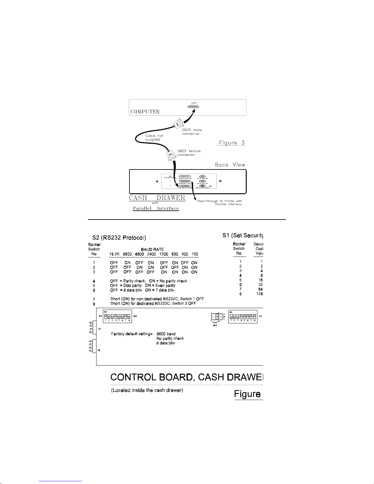
Model CR3001 - Parallel Interface:
Connect the drawer to the computer as shown in Figure 3. Connect
the power adapter output to the power input jack.
Whenever the POS application software transmits the pre-set
security code to the computer’s parallel (LPT1) port, the drawer will
open. The security code was pre-set by the manufacturer at (07
Hex) and can be re-configured as shown in Figure 4. Under normal
operations, the selected pre-set code should be a non-displayable
ASCII character.
NOTE:
Other parallel devices, such as a printer, can be con-
nected to the same parallel port.
INSTALLATION
Your cash drawer has been pre-assembled to make the installation
as simple as possible.
Model CR3000
1. Remove the cash drawer from its shipping container.
2. Remove the keys and interface cable from its plastic bag.
3. Connect the interface cable to the printer.
4. Connect the other end of the interface cable to the “Control
Signal Input” of the cash drawer.
Model CR3001 with serial interface
1. Remove the cash drawer from its shipping container.
2. Remove the keys and interface cable from its plastic bag.
3.Connect the DB9F connector of the interface cable to the COM1
or COM2 port of the computer.
4.Connect the DB25F connector of the interface cable to the DB25M
"Serial Input From Computer" connector on the cash drawer.
NOTE:
The interface cable may not be used for other
applications.
5. Connect the power adapter output to the “Power Input From
Adapter” connector on the cash drawer.
3

Model CR3001 with parallel interface
NOTE:
The parallel interface cash drawer does not come with
an interface cable. Any standard centronic parallel
printer cable may be purchased to interface between the
computer and the cash drawer.
1. Remove the cash drawer from its shipping container.
2. Remove the keys from its plastic bag.
3. Connect a parallel interface cable between the parallel port on
the computer and the “Parallel Input From Computer” connector
on the cash drawer.
4. Connect the power adapter output to the “Power Input From
Adapter” connector on the cash drawer.
FUNCTIONAL TEST
The following test sequence will verify that your cash drawer is
working properly. Before you start this procedure, you must install
the cash drawer correctly as outlined in the installation section
NOTE:
The actual key entries are enclosed within
quotation marks (“ “). Do not type the quotation
marks as part of your entry.
Model CR3000, CR3001 with dedicated interface:
1. From the C prompt type “MODE COM1 96,N,8,2” and press
ENTER.
2. Type “TYPE CON>COM1” and press ENTER.
3. Type any alphanumeric character(s) and press ENTER. The
cash drawer will open.
4. To return to the C prompt press and hold the CTRL key while
depressing the letter C.
4

MODEL CR3001 with non-dedicated interface
1. From the C prompt type “MODE COM1 96,N,8,2” and press
ENTER.
2. Type “TYPE CON>COM1” and press ENTER.
3. TYPE “^G” and press ENTER. The cash drawer will open if the
security code is 07 Hex as set by the manufacturer.
NOTE:If another security code has been selected to open the
cash drawer then the corresponding ASCII character must be
substituted to open the drawer.
4. To return to the C prompt press and hold the CTRL key while
depressing the letter C.
MODEL CR3001 with parallel interface
1. From the C prompt type “ECHO ^G>LPT1” and press ENTER.
The cash drawer will open if the security code is 07 Hex as set
by the manufacturer.
NOTE:
If another security code has been selected to
open the cash drawer then the corresponding ASCII character
must be substituted to open the drawer.
The computer has automatically returned to the C prompt.
5

KEY LOCK OPERATION
All cash drawers have a three position key lock for maximum
security. The fully counter clockwise lock position offers
maximum security. The cash drawer can not be opened by
computer or an individual when the lock is in the full counter
clockwise position. With the lock in the center position, the drawer
will open when an electronic pulse is received from either the
printer or computer. The cash drawer is manually opened when the
lock is in the full clockwise position.
Model CR3000, CR3001 Keylock Operation:
KEYLOCK
:Drawer securely locked. Can not be opened by computer, printer,
or manually.
:Opens the drawer with the supplied key.
:Automatically opens the drawer by computer or printer control.
6

SPECIFICATIONS
MECHANICAL:
Weight 14.3 lb. (6.5 kg)
Height 3.3 in. (8.5 cm)
Width 15.7 in. (40 cm)
Depth 16.1 in. (41 cm)
ELECTRICAL:
INPUT TO SOLENOID (CR3000, CR3001)
Pulse Amplitude 12VDC to 24VDC
Pulse Width 100 milliseconds to 200 milliseconds
Pulse Duty Cycle 10% maximum
Peak Current 1 Ampere
POWER ADAPTER (CR3001)
Input Voltage 120 VAC. +10%-20%
50-60 Hz
20W
12 VAC at 1A
SERIAL INPUT (CR3001)
Data Format Standard RS232C
Protocol (see Fig. 4)
Baud Rate 150,300,600,1200,2400,
Parity None*, Even, or Odd
Data bits 7 or 8*
Handshake None
Security Code(CR3001) 1-255; 7*
Open Drawer Indicator Open collector, conducting when
opened
4800, 9600*, 19,200
* Denotes factory default settings.
PARALLEL INPUT (CR3001)
Data Format Standard Centronics parallel interface
Security Code 1-255; factory preset value = 7
Open-Drawer Indicator Open-collector, conducting when
opened
7

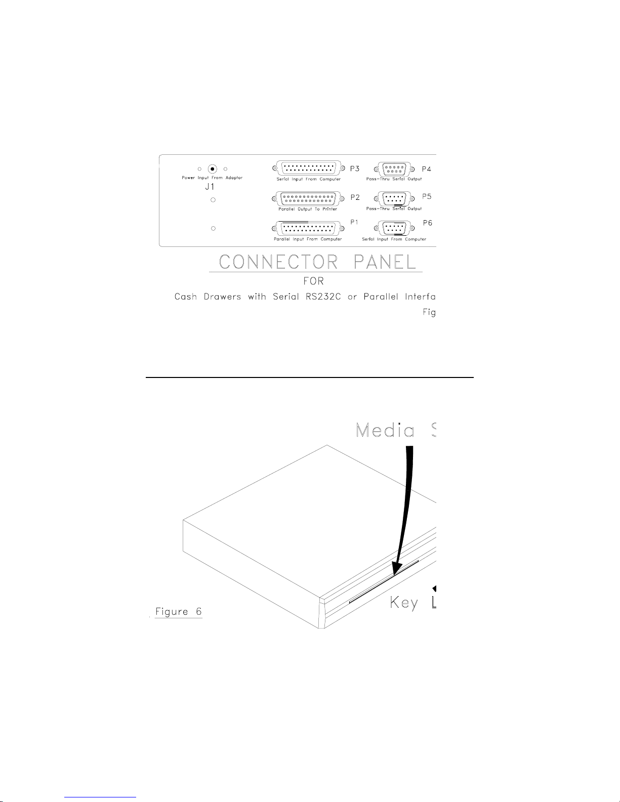
CONNECTOR PIN OUT
Figure 5 will show the connector arrangement for the CR3001 cash
drawer. The following char ts will show the function of each pin.
P1 (DB25 M) - Parallel Input From Computer
Pin # Function Pin # Function
1 -Strobe 13 Select
2 Data 0 14 -Auto Feed
3 Data 1 15 -Error
4 Data 2 16 -Initialized printer
5 Data 3 17 -Select input
6 Data 4 18 Ground
7 Data 5 19 Ground
8 Data 6 20 Ground
9 Data 7 21 Ground
10 -Ack 22 Ground
11 Busy 23 Ground
12 Paper end 24 Ground
25 Ground
P2 (DB25F) - Parallel Output to Printer
Pin # Function Pin # Function
1 -Strobe 13 Select
2 Data 0 14 -Auto Feed
3 Data 1 15 -Error
4 Data 2 16 -Initialized printer
5 Data 3 17 -Select input
6 Data 4 18 Ground
7 Data 5 19 Ground
8 Data 6 20 Ground
9 Data 7 21 Ground
10 -Ack 22 Ground
11 Busy 23 Ground
12 Paper end 24 Ground
25 Ground
8

P3(DB25M) - Serial Input From Computer
Pin # Function
1 No connection
2 Receive data from computer
3 Transmit data to computer
4 RTS, Request To Send; from computer (tied to pin 5 internally)
5 CTS, Clear To Send; to computer (tied to pin 4 internally)
6 DSR, Data Set Ready; to computer (tied to pins 8 & 20 internally)
7 Ground
8DCD, Data Carrier Detect; to computer (tied to pins 6 & 20)
9No connection
10No connection
11No connection
12-17 No connection
18 POS pr inter interface; paired with pin 25
19 No connection
20 DTR, Data Terminal Ready; from computer (tied to pins 6 & 8)
21-24 No connection
25POS printer interface, paired with pin 18
P4(DB9F) - Pass Thru Serial Output
Pin # Function
1Connected to pin 1 of P5
2 Receive data from printer
3Transmit data to printer
4No connection
5Ground
6 Connected to pin 6 of P5
7 Connected to pin 7 of P5
8 Connected to pin 8 of P5
9 Connected to pin 9 of P5
P5(DB9M) - Pass-Thru Serial Output
Pin # Function
1Connected to pin 1 of P4
2Receive data from printer
3Transmit data to printer
4 No connection
5 Ground
6Connected to pin 6 of P4
7Connected to pin 7 of P4
8Connected to pin 8 of P4
9Connected to pin 9 of P4
9

P6 (DB9M) - Serial Input from computer
Pin # Function
1 DCD, tied to pins 4 & 6
2Transmit data to computer
3Receive data from computer
4 DTR, tied to pins 1 & 6
5 Ground
6 DSR, tied to pins 1 & 4
7 RTS, tied to pin 8
8 CTS, tied to pin 7
9 No connection
CONTROLLER BOARD JUMPERS
( Located inside the drawer)
J12 - Connects to “Input Power Jack”
JP1 - Not used
JP2 - Jump 1-2* for non-dedicated RS232
Jump 3-4 for dedicated RS232
JP3 - Jump 1-2 for input data applies to P3-3 or P6-2
Jump 3-4* for input data applies to P3-2 or P6-3
J10 - Connects to solenoid, no polarity
10

11
12
13
 Loading...