

POSline SM2430 User Manual

Manual del Usuario
SM2430
ESPECIFICACIONES SUJETAS A CAMBIO SIN PREVIO AVISO.

No warranty of any kind is made in regard to this material, including, but not limited to, implied
warranties of merchantability or fitness for a particular purpose. We are not liable for any errors con
tained herein nor incidental or consequential damages in connection with furnishing, performance
or use of this material.
No part of this document may be reproduced, transmitted, stored in a retrieval system, transcribed, or translated into any language or computer language in any form or by any means electronic, mechanical, magnetic, optical, chemical, manual or otherwise, without express written
consent and authorization.
We reserve the right to make changes in product design without reservation and without notification. The material in this guide is for information only and is subject to change without notice.
All trademarks mentioned herein, registered or otherwise, are the properties of their various
respective owners.
Copyright © 2004. All rights reserved.
Radio Notice
This equipment generates, uses and can radiate radio frequency energy. If not installed and
used in accordance with the instructions in this manual, it may cause interference to radio commu
nications. The equipment has been tested and found to comply with the limits for a Class A computing device pursuant to EN55022 and 47 CFR, Part 2 and Part 15 of the FCC Rules. These
specifications are designed to provide reasonable protection against interference when operated in
a commercial environment.
Radio and Television Interference
Operation of this equipment in a residential area can cause interference to radio or television
reception. This can be determined by turning the equipment off and on. The user is encouraged to
try to correct the interference by one or more of the following measures:
* Reorient the receiving antenna.
* Relocate the device with respect to the receiver.
* Move the device away from the receiver.
* Plug the device into a different outlet so that the device and the receiver are on different
branch circuits.
If necessary the user may consult the manufacturer, an authorized dealer, or experienced
radio/television technician for additional suggestions. The user may find the following booklet pre
pared by the Federal Communications Commission helpful: “How to Identify and Resolve Radio-TV
Interference Problems.” This booklet is available from the U.S. Government Printing Office, Wash
ington, DC 20402 U.S.A., Stock No. 004000003454.
For CE-countries
This scanner is in conformity with CE standards. Please note that an approved, CE-marked
power supply unit should be used in order to maintain CE conformance.
i

Laser Safety
The Dual-Laser Omnidirectional Vertical Scanner complies with safety standard
IEC 60825 for a Class I laser product. It also complies with CDRH as applicable
to a Class IIa laser product. Avoid long term staring into direct laser light.
Radiant Energy: The Dual-Laser Omnidirectional Vertical Scanner uses two
low-power visible laser diodes operating at 650nm in an opto-mechanical scan
ner resulting in less than 3.9µW radiated power as observed through a 7mm
aperture and averaged over 10 seconds.
Do not attempt to remove the protective housing of the scanner, as unscanned
laser light with a peak output up to 0.8mW would be accessible inside.
Laser Light Viewing: The scan window is the only aperture through which
laser light may be observed from this product. A failure of the scanner motor,
while the laser diode continues to emit a laser beam, may cause emission lev
els to exceed those for safe operation. The scanner has safeguards to prevent
this occurrence. If, however, a stationary laser beam is emitted, the failing scan
ner should be disconnected from its power source immediately.
-
-
-
Adjustments: Do not attempt any adjustments or alteration of this product. Do
not remove the protective housing of the scanner. There are no user-service
-
able parts inside.
Caution: Use of controls or adjustments or performance of procedures other
than those specified herein may result in hazardous laser light exposure.
Optical: The use of optical instruments with this product will increase the eye
hazard. Optical instruments include binoculars, magnifying glasses, and micro
-
scopes but do not include normal eye glasses worn by the user.
ii

Table of Contents
1 Introduction.................................................. 1
2 Unpacking.................................................... 1
3 Finding Your Way Around .......................... 2
4 Connecting and Mounting............................ 2
4.1 Power................................................... 2
4.2 Verifying Scanner Operation................ 3
4.3 Mounting .............................................. 4
4.4 Connecting to the Host ........................ 8
5 Setting Up the Scanner ............................... 8
5.1 Scan Test............................................. 8
5.2 Set Up ..................................................8
6 Operation................................................... 10
6.1 LED Indications.................................. 10
6.2 Beeps................................................. 11
6.3 Changing the Beep Volume ............... 11
6.4 Sleep Mode........................................ 11
6.5 Controlling from a POS System ......... 12
7 Maintaining the Scanner............................ 13
7.1 Cleaning the Scan Window................ 13
7.2 Replacing the Interface Cable............ 13
8 Specifications ............................................ 14
9 Dimensions................................................ 15
10 Pin Assignments...................................... 17
11 Troubleshooting ...................................... 18
iii

1 Introduction
This advanced scanner is a proud to be among the world's first dual-laser presentation scanners, and it incorporates numerous record-breaking features. Its
pioneering application of dual laser diodes drastically enhances scanning
power by doubling the scan lines, broadening scan angle and intensifying the
scan pattern across the scan field. With this state-of-the-art technology, it is
able to deliver a comprehensive 32-line scan pattern cycling at 2400 scans per
second. The scanner is additionally equipped with Z-SCAN technology—an
innovative ASIC hardware decode protocol that provides real-time decoding
that effectively shortens customer transaction time.
The broad, omnidirectional scan field effectively facilitates hands-free scanning
of barcodes on products of many different shapes. Also, the scanner is pro
grammed with multiple beeper tones and barcode data edition functions to
accommodate a variety of applications.
-
2 Unpacking
The Dual-Laser Omnidirectional Vertical Scanner package should contain:
1 ea. Dual-Laser Omnidirectional Vertical Scan-
ner, with attached mounting plate
1 ea. 5V power adapter (model depends on
electrical requirements of your geographic
location)
1 ea. User's Manual (this booklet)
1 ea. Programming Guide
1 ea. Connection cable (This cable is usually,
but not always, supplied. Model depends
on customer needs.)
Please check for any damaged or missing items; contact your dealer if there is
a problem.
1
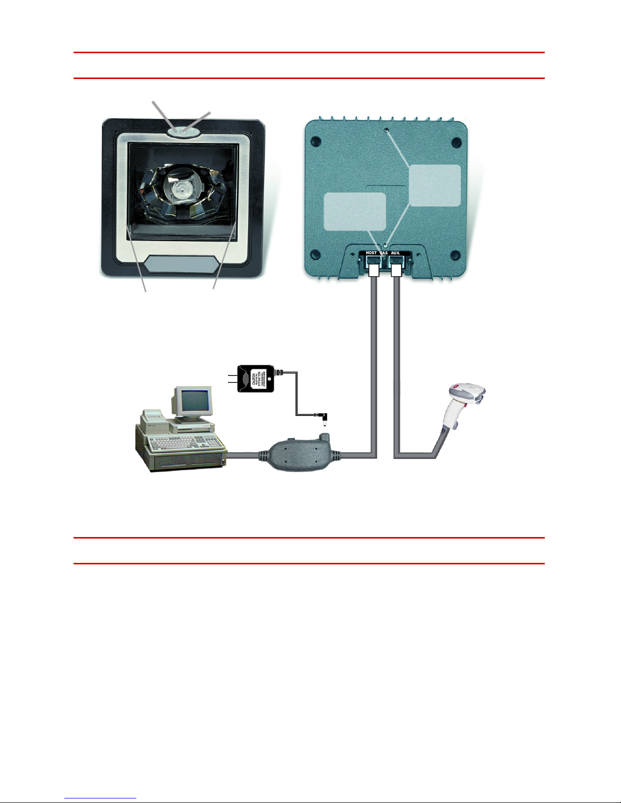
3 Finding Your Way Around
LED indicator
scan window
host POS
terminal
push
button
AC adapter
EAS
connection
(optional)
back
mount
holes
(optional)
auxiliary scanner
4 Connecting and Mounting
4.1 Power
The scanner requires a minimum of 300mA at 5 Vdc power. The interface cable
that comes with the scanner supports both direct power (where the scanner
takes power from the host machine) and external power (that's what the sup
plied power adapter is for). A sufficiently robust POS system can support a
scanner successfully without external power; a POS system with a barely ade
quate power supply may produce erratic performance (either of the POS system itself, or of the scanner, or both) when a scanner is attached. Unless you
Figure 1: Overview
-
-
2
are sure your POS system can handle the load, it is recommended that you use
the supplied power adapter. When an external adapter is connected, the scan
-
ner does not take power from the host.
The scanner turns on when power is supplied, and turns off when power is
removed. There is no on/off switch on the scanner itself.
Use only an AC/DC power adapter approved for the scanner. Use of other
power supplies may cause damage to the product, and void the factory war
-
ranty.
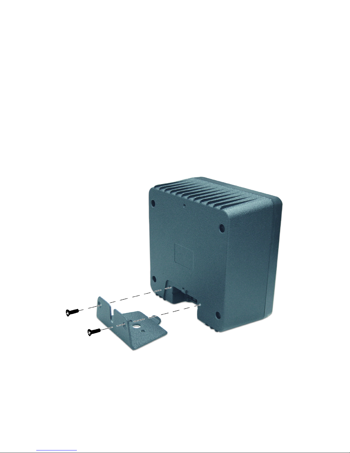
4.2 Verifying Scanner Operation
Before mounting your scanner, please follow the procedure below to verify
scanning operation.
1. Take out the screws and remove the mounting plate.
Figure 2: Remove Mounting Plate
3

2. Insert the 8-pin modular plug of the power link cable into the “host” connec-
tor in the back of the scanner until a firm click is heard.
3. Plug the power adapter into the jack on the power link cable. (See Figure
1.)
4. Plug the AC end of the power adapter into an AC outlet. The scanner pow-
ers up, the buzzer sounds four beeps and the LED indicator glows blue.
5. Present a known-good test barcode to the scanner. The scanner should
issue a short beep and the LED should flash red momentarily. [If the scan
-
ner is connected to a keyboard wedge for this test, it should read one bar-
code, beep, then remain with a red LED indicating light. This is normal
when the keyboard wedge is not connected to a live host terminal.]
Note: If the scanner does not produce any beeps, or produces the wrong
beeps, or the LED does not light, remove the power connection and refer to the
section on Troubleshooting.
4.3 Mounting
After the scanner passes its verification test (Section 4.2 above), proceed with
mounting.
The scanner should be installed in a location away from direct sunlight; high
levels of ambient light reduce scanner effectiveness.
The two basic styles of mounting are a) with the included mounting plate, and
b) with a custom bracket (not included) for back mounting. If an auxiliary hand
held scanner is to be attached, it must be properly connected as part of the
mounting process.
-
4
 Loading...