


FJ1100L User Manual
FJ1100L User Manual
R1.1
Author Revision Changes Date
jinyi 1.1 Initial version 2018-01-03

FJ1100L User Manual
Contents
1 Introduction .................................................................................................................. 3
ID and Tooling Design ...................................................................................................................... 3
2 Hardware ............................................................................................................................. 4
Physical and Electrical Specifications ................................................................ 4
Input/Output .................................................................................................... 4
Cellular Communication.................................................................................... 4
GPS Specification .............................................................................................. 4
Harnesses .......................................................................................................... 5
Hardware Introduction ..................................................................................... 6
Basic RF Performance ....................................................................................... 7
Safety ....................................................................................................................... 7
3 Software Features ............................................................................................................... 8
Basic Software................................................................................................... 8
Power Modes .................................................................................................... 9
Reset ........................................................................................................................ 9
Test Method ...................................................................................................... 9
Hardware .......................................................................................................... 9
Software Test ...................................................................................................................... 9
4 Event codes ................................................................................................................... 9
FCC Regulations .................................................................................................................... 11
FJ1100L User Manual
1 Introduction
The FJ1100L is a vehicle tracking device that uses a GPS satellite receiver to determine
location information and a CAT-1 transceiver to communicate information to and from a
land based server. In addition, the FJ1100L has several Inputs that may be configured to
detect states of sensors and Outputs that can control accessories.
The FJ1100L is powered by standard vehicle power (12V or 24V). It accepts several
harnesses: a 2 wire power harness, and 4 wire IO harness.
Communications between the FJ1100L and the server are carried out using the UDP protocol
with sequence acknowledgment messages to confirm receipt of messages by the server.
Configuration of the device can be conducted using serial communications over the USB
port or by sending SMS messages to the device.
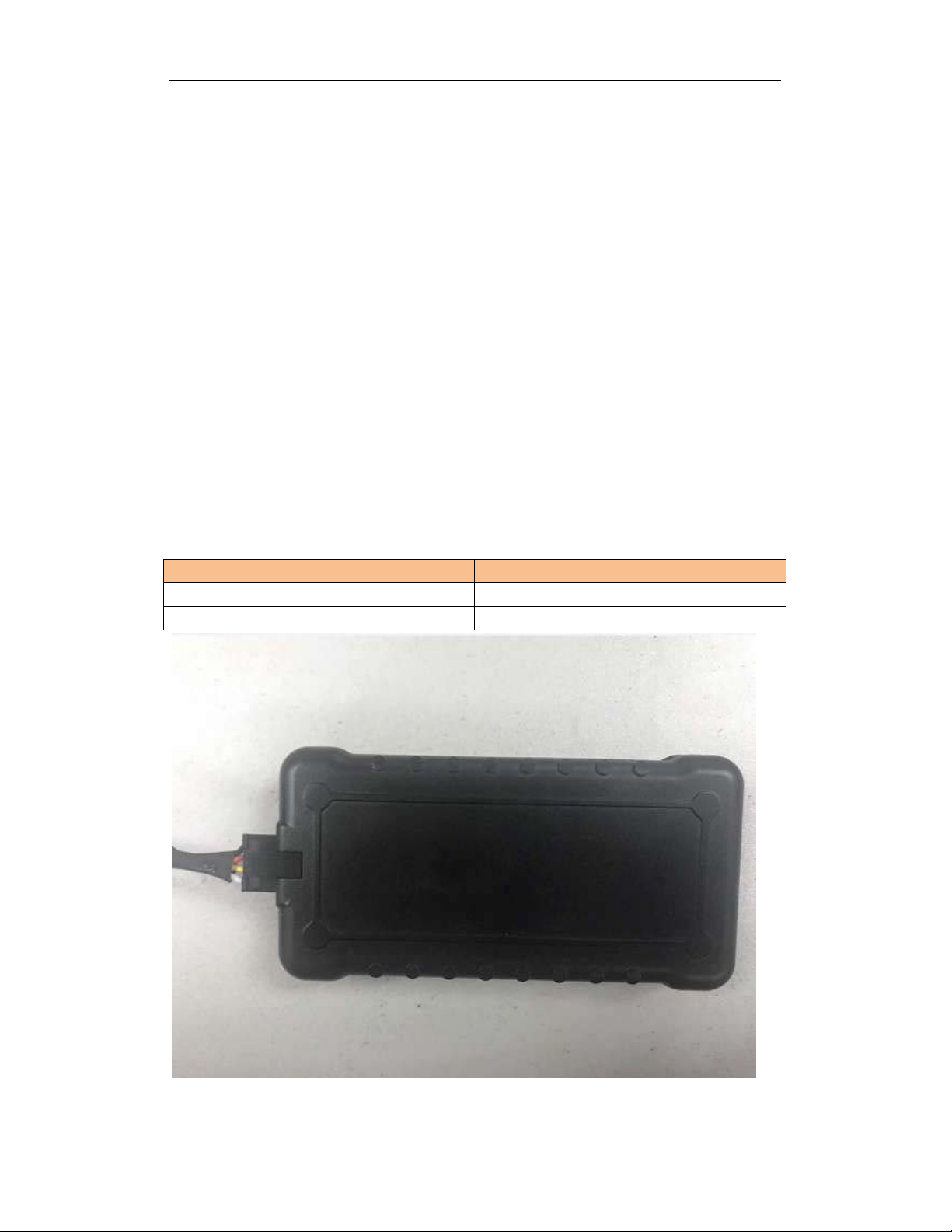
ID and Tooling Design
The housing will be provided by customer. The product appearance is shown as f ollows:
Item
Dimension 103mm *53mm *18.65mm
Weight
Definition
/

2. Hardware
Physical and Electrical Specifications
Dimensions: 103mm *53mm *18.65mm
Weight: 74.5 g (with optional battery)
FJ1100L User Manual
Input Voltage: 4-36VDC
Power consumption:
- Active mode: 200mA @12VDC
- Sleep mode: <2mA @12VDC
Operating temperature: -30
Storage temperature: -40℃to 85℃
Input/Output
Digital Inputs: 1
Relay driver Outputs: 1
Function LEDs: 2
GPS Status GREEN
Cellular Status ORANGE
Cellular
℃
to 75
Communication
℃
Operation Mode:
Operation Band
Lte_B13
Modulation: Uplink:QPSK
FDD_LTE(Cat1)
: Lte_B4,
Downlink: QPSK/16QAM
2.5 GPS Specification
‐167dBm Tracking Sensitivity
Location Technology(72 channel GPS)
Location Accuracy (2 meter CEP50)

Harnesses
FJ1100L User Manual
There are1 harnesses that may be used with the
1. 4 wire power and I/O harness
FJ1100L
:
The picture above shows the 4 wire power and I/O harness. The wiring details are:
Power and I/O Harness 4 wires
1. Black
2. Red
3. Yellow
V-
is connected to Negative or Ground
V+
is connected to Positive , +12VDC or +24VDC
Input0
is an input biased high, negative trigger.
4. White Output 0 is an output, open collector, may be used for Starter Disable.

FJ1100L User Manual
Hardware features
The FJ1100L provides support for specialized hardware features through extended AT
commands. The features supported include the following.
GPS
The major functionality of the GPS module is to compute the correlation results between the
incoming signal and the selected PRN code based on certain Carrier Doppler Frequency, Code
Doppler Frequency, code phase, carrier phase, and the particular satellite the module is
tracking or acquiring.
GPIO
Two GPIO pins, GP1 and GP2, are presented to the external environment on the main
connector. They are general purpose bidirectional lines capable of providing system
interrupts to generate a report or drive logic levels to external devices. These pins default to
input. GP1 is pulled down representing 0 when disconnected; GP2 is pulled up representing
logical 1 when disconnected. They should be asserted to a known value if used. GP1 is
intended to use for Ignition Sensing.
LED’s
Two LED status indicators are provided to verify correct installation and operation. The
status LEDs are color coded and directly convey the status of the CAT-1 and GPS subsystems
as described in the table below. Their valid operation also indicates operational status and
power.
The device provides user control allowing the LEDs to be extinguished once installation is
verified. This feature reduces power and further conceals the device Tracker from untrained
parties wishing to defeat its operation.
LED
GREEN GPS
ORANG
E
Function
CAT_1
Battery Monitor
The battery monitor is internal analog input scaled such that the DC value of the power input
pin to the device system is measured. This value is scaled to span the most significant 8 bits
of the A/D and consequently covers a scale from 0 to 25.5 Volts.
Status
On: GPS satellites acquired and
Locked
Flash Slow
in progress
Off: No power or GPS subsystem
fault
On: Indicates
made
Flash Slow
initialized but no connection
Flash Fast
process
Off: No power or
subsystem fault
: GPS satellite search is
CAT_1
connection is
: CAT_1 subsystem
: CAT_1 initialization in
CAT_1

_27RB
_27RB
FJ1100L User Manual
Timers
Timers resident on the CAT-1 baseband chip generate periodic interrupts for power down
wakeup, watchdog support, report generation and other timer related functions. Report
timers are supported by related AT command and cause generation of periodic reports.
Motion Detect
A factory populates option for motion detector is provided. If populated at the time the
FJ1100L is manufactured, this option will work with firmware power down options to keep
the FJ1100L in a very low power down state until motion is detected. Upon wakening, a
report can then be generated.
Basic RF Performance
LTE BAND4 LTE BAND13
BW Mode Maximum Target BW Mode Maximum
22.5dBm±1.5
22.5dBm±1.5
22.5dBm±1.5
22.5dBm±1.5
22.5dBm±1.5
22.5dBm±1.5
22.5dBm±1.5
22.5dBm±1.5
B4/B13 TX Performance
QPSK
5MHZ
16QAM
10MH
Z
15MH
Z
20MH
Z
Minimum Output Power <-39dBm
QPSK
16QAM_UP
_27RB
QPSK
16QAM_UP
QPSK
16QAM_UP
Transmit OFF power <-48.5 dBm
5MHZ
10MHZ
QPSK
16QAM
QPSK
16QAM_UP_27RB
22.5dBm±1.5
22.5dBm±1.5
22.5dBm±1.5
22.5dBm±1.5
Frequency Error |Δf| ≤ (0.1 PPM + 15 Hz)
Error Vector Magnitude
(EVM)
PUSCH 17.5@QPSK BPSK ;12.5%@16QAM
PUCCH 17.5%
PRACH 17.5%@FFS

Carrier leakage
FJ1100L User Manual
<-24.2dBc@3.2 dBm ±3.2dB
<-19.2dBc@-26.8 dBm ±3.2dB
<-9.2dBc@-36.8 dBm ±3.2dB
Adjacent Channel
Leakage power Ratio
<-32.2dBc@ACPR1_UTRA
<-35.2dBc@ACPR2_UTRA
<-29.2dBc@ACPR_EUTRA
<-36
dBm@BW=1 9 kHz ≤ f < 150 kHz
KHz
<-36
Transmitter Spurious
emissions
dBm@BW=1
0KHz
<-36
150 kHz ≤ f < 30 MHz
dBm@BW=1 30 MHz ≤ f < 1000 MHz
00KHz
<-30dBm@B
W=1MHz
1 GHz ≤ f < 12.75 GHz
Frequency Range
:
B4: TX (1710--1755) MHZ RX (2110--2155) MHZ
B13: TX (698--716) MHZ RX (746--756) MHZ
Safety
Items
Drop Design 1.2meter 6 direction standard drop test
Temperature Range -40 to 85°C Operation
Humidity: 20% to 90% Operation
Altitude: -500 to +18,000m
Requirement
-50 to +100° C Storage
10% to 95% Storage
Safety UL Listing
Others Operator Requirement Industry Canada/ AT&T (optional)
ESD Requirement 15KV non-conductive
 Loading...