


FJ1000LS
FJ1000LS User Manual
Positioning Universal
1

FJ1000LS
Contents
1 Introduction ....................................................................................................................3
1.1ID and Tooling Design.......................................................................................................3
2 Hardware.........................................................................................................................3
2.1 Physical and Electrical Specifications ..............................................................................3
2.2 Input/Output...................................................................................................................3
2.3 Cellular Communication...................................................................................................3
2.4
Harnesses.........................................................................................................................3
2.5 Event Codes ....................................................................................................................4
2.6 System network structure...............................................................................................5
2.7 Appearance and installation instructions........................................................................5
3 USER MANUAL.................................................................................................................6
3.1INTRODUCTION...............................................................................................................6
3.2List...................................................................................................................................6
3.3Description......................................................................................................................7
2
FJ1000LS
1.1 ID and Tooling Design
Dimensions: 80.5mm*52mm*18mm
Weight: 60g (with optional battery)
2.1Physical and Electrical Specifications
Input Voltage: 7-30VDC
Power consumption:
- Active mode: 100mA @12VDC
- Sleep mode: <8mA @12VDC
Operating temperature: -30℃ to 80℃
Storage temperature: -40℃to 85℃
2.2Input/Output
Download and debug port: 1
SWDInterface: 1
Function LEDs: 2
2.3 Cellular Communication
Operation mode :LTE/GPS
Operation band :LTEB12/B25/B26;GPS 1.57542GHz
Modulation: QPSK/16QAM
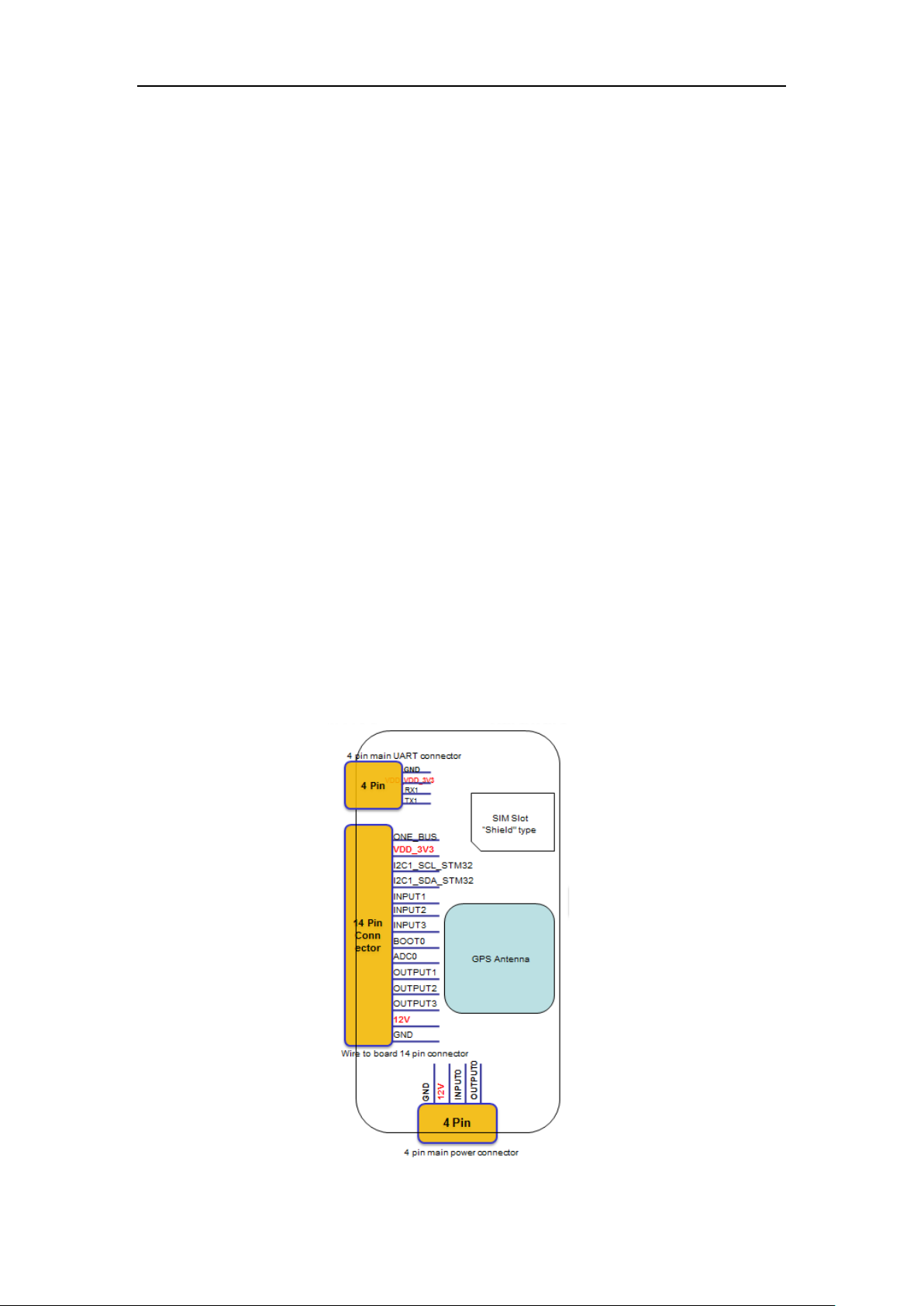
2.4 Harnesses
There are 3 harnesses that may be used with the FJ1000LS:
1. 4 wire power and I/O harness
2. 4 wire uart
3. 14 wire power and I/O harness
The picture as below.
3

FJ1000LS
2.5 Event Codes
The table below relates the Event codes in the message to the reason the message was
generated:
Message # Message Type Description
0 Interval Auto Report (auto report when moving)
1 Vibration Vibration alarm(report when GPS is OFF and vibrati on detected)
2 Power Disconnect Power cut alarm (report when external power is cut off)
3 Power Connect Power connected alarm (external power has been connected)
4 Ignition ON Hardwired or Virtual Ignition ON detected
5 Ignition OFF Hardwired or Virtual Ignition OFF detected
6 Input 2 High Input2 high alarm
7 Input 2 Low Input2 low alarm
8
9
10
11
12
2.6 System network structure
GPS alarm is currently the most advanced security Settings. GPS alarm more expensive than
ordinary burglar alarm, and need to pay t he additional service fe e, so the po pularity is not high.
And alarm is based on a GPRS net work communicati on network, combinin g with the i ntelligent
linkage of mobile phone and car anti-theft, t his kind of alarm alarm is not restricted by di stance,
overlay network is wide, but need to pay the monthly rent al. Buying guide to edit GPS alarm
when the choose and buy, need to pay attenti on to is t he compa ris o n of sever al c ommon GP S
performance.
2.7 Appearance and installation instructions
3.1 Introduction.
This chapter is user manual for FJ1000LS.
3.2List.
4

1.One UART cables.
2.The FJ1000LS devices.
FJ1000LS
5

FJ1000LS
3.One DC 12V cable.
3.3 Description.
1.Connect the UART cable to the UART interface of MCU on the device, the other side
connect to PC, you can communication to MCU wit h UA RT cable.
6

FJ1000LS
2. Connect the DC 12V cable to the connector of J203 on the device, the other side
connect to DC 12V, you can use the DC 12v cable to supply power.
4. The other interfaces of the FJ1000LS device are shown in the following pictures.(The
Modem UART 1 on device is for modem debug and update firmware).
7

mcu download
test point
GPS UART test point
FJ1000LS
8

FJ1000LS
NOTE: This equipment has been tested and found to comply with the li mits for a Class B
digital device, pursuant to part 15 of the FCC Rules. These limits are designed to provide
reasonable protection against harmful interference in a residential installation. This equipment
generates, uses and can radiate radio frequency energy and, if not installed and used in
accordance with the instructions, may cause harmful interference to radio communications.
However, there is no guarantee that inter ference will not occur in a particula r instal lation. I f this
equipment does cause harmful interference to radio or television reception, which can be
determined by turning the equipment off and on, the u ser is encouraged to try to correct the
interference by one or more of the following measures:
—Reorient or relocate the receiving antenna
—Increase the separation between the equipment and receiver.
—Connect the equipment into an outlet on a circuit different from that to which the receiver is
connected.
—Consult the dealer or an experienced radio/TV tech ni cian for help.
This device complies with part 15 of the FCC Rules. Operation is subject to the following two
conditions: (1) This device may not cause harmful interference, and (2) this device must
accept any interference received, including interf erence that may cause undesired operation.
Changes or modifications not expressly approved by the party responsible for compliance
could void the user's authority to operate the equipm ent.
Keep at least 20cm away from the unit when it works.
9
 Loading...