

POSI LOCK PH-102T, PH-100T, PH-123T, PH-102TV, PH-102TDA Instructions-parts List Manual
...
100-TON & 200-TON
!
!
!
Hydraulic Puller Systems
INSTRUCTION & PARTS SHEET
IMPORTANT: READ CAREFULLY!
IMPORTANT RECEIVING INSTRUCTIONS:
Visually inspect all components for shipping damage. Shipping
damage is not covered by warranty. If shipping damage is found
notify the carrier at once. The carrier is responsible for all repair
and replacement costs resulting from damage in shipment.
SAFETY FIRST:
It is impossible to predict the exact force needed for every
pulling situation. The amount of press-t and force of removal
can vary greatly between jobs. The set-up requirements along
with the size, shape and condition of the parts being pulled
are all variables which must be considered. Remember that a
signicant amount of force can be exerted with a puller. Respect
this force and always observe safety precautions. Failure to
comply with the following cautions and warnings could cause
equipment damage or personal injury.
WARNING: DO NOT touch or handle hydraulic hoses or
ttings with pressure in the system. Escaping oil under
pressure may cause serious injury. If oil is injected under the
skin see a doctor immediately.
DO NOT make any electrical adjustments with electrical power
active in the system.
IMPORTANT: Inspect puller for dents, cracks, or
excessive wear before each use. Immediately replace
worn or damaged parts.
It is recommended to use 3-jaw puller whenever possible for a
more secure grip, a more even pulling force and better stability.
Cover application with a protective blanket before applying
force. Since high force is applied on the part being pulled,
breakage may occur and user may be exposed to ying debris.
Use hydraulic gauges in each hydraulic system to indicate safe
operating loads.
Apply force gradually. Be sure the puller is square with the
component to be pulled.
Wear safety glasses or other approved eye protection.
Keep hands away from possible pinching points.
Always make sure the puller is aligned with the shaft.
Select the appropriate ram extender for each application.
DO NOT make or break any hydraulic connections with pressure
in the system.
DO NOT overload the equipment. Use the right size puller.
DO NOT stand on, under or near the puller while in use. Keep
hands, feet and clothing away from moving parts.
To avoid personal injury and equipment damage, make sure
all hydraulic components withstand the maximum hydraulic
pressure of 700 bar (10,000 psi).
Make sure all system components are protected from external
sources of damage, such as excessive heat, ame, moving
machine parts, sharp edges and corrosive chemicals.
Always check to ensure that all cylinders and components are
securely fastened.
Always place the puller in the lowest position and remove ram
extenders while transporting.
Keep slide rollers and mast clean and lubricated.
Always keep puller hoist vertical and the control valve closed
when not adjusting vertical position.
A small amount of oil seepage is normal from breather vent on
hoist cylinder.
Use only genuine POSI LOCK parts and endorsed hydraulic
components.
CAUTION: Make sure that all items being pulled are
supported by a means other than the puller. When
using a puller in excess of 50 pounds, support puller by other
means than a single person. Do not use the puller for lifting or
supporting objects.
Avoid sharp bends and kinks in hoses as they may lead to
premature hose failure. Inspect hoses and ttings for leaks or
damaged areas. Immediately discard and replace damaged
components.
1
POSI LOCK® 100-TON & 200-TON
max. 66.54 in.
(1690 mm)
min. 26.50 in.
(673 mm)
77.95 in.
(1980 mm)
40.98 in. (1041 mm)
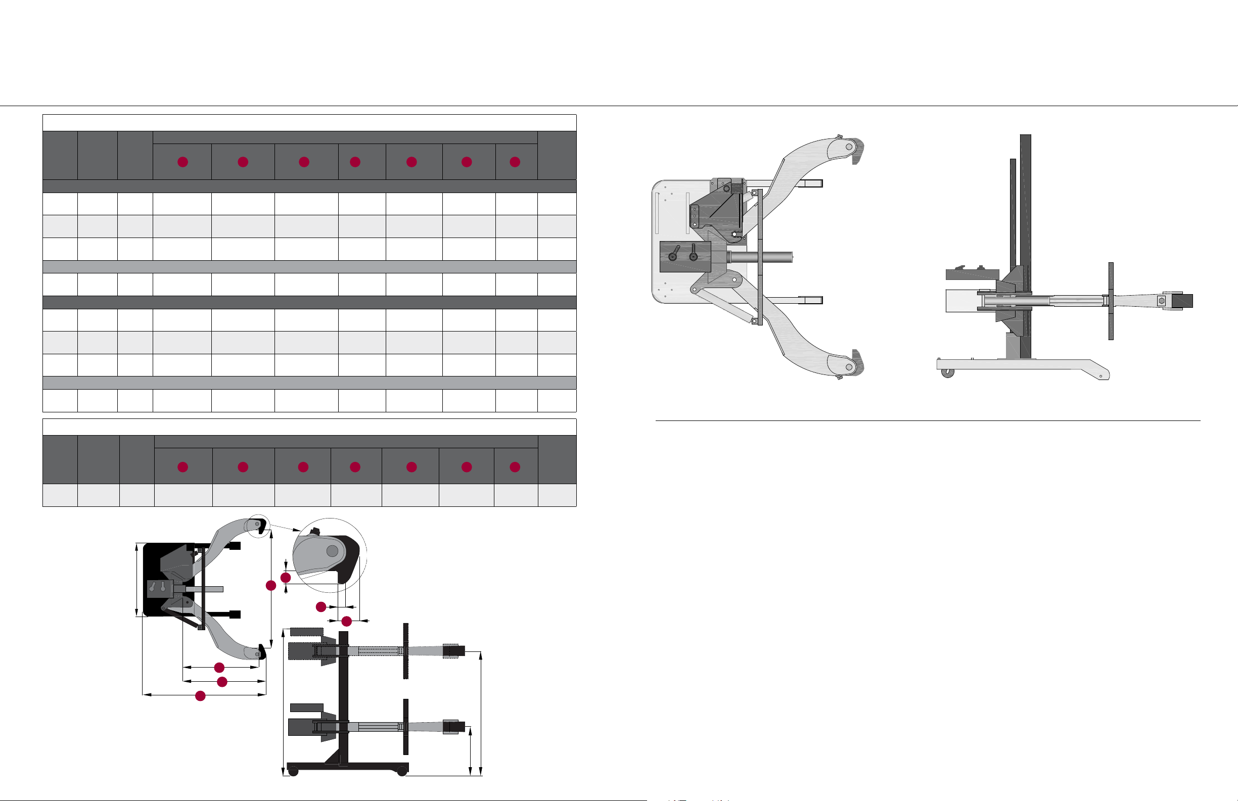
POSI LOCK® 100-TON & 200-TON
Hydraulic Puller Systems
Instructions applicable to part numbers described below:
Portable 100-Ton Hydraulic Puller Systems
Dimensions
PH-
PH-
PH-
PH-
PH-
Capacity
Tons (kN)
100 tons
(890 kN)
100 tons
(890 kN)
100 tons
(890 kN)
100 tons
(890 kN)
100 tons
(890 kN)
100 tons
(890 kN)
100 tons
(890 kN)
100 tons
(890 kN)
Model
Number
Single Acting
PH -102T
PH -100 T
PH -123T
Single Acting Vertical
102T V
Double Acting
102T DA
100TDA
123 TD A
Double Acting Vertical
102DATV
Number
of Jaws
2
3
2/3
2
2
3
2/3
2
Spread
A
in. (mm)
7.5 to 70 in.
(191 to 1778 mm)
7.5 to 70 in.
(191 to 1778 mm)
7.5 to 70 in.
(191 to 1778 mm)
7.5 to 70 in.
(191 to 1778 mm)
7.5 to 70 in.
(191 to 1778 mm)
7.5 to 70 in.
(191 to 1778 mm)
7.5 to 70 in.
(191 to 1778 mm)
7.5 to 70 in.
(191 to 1778 mm)
Overall Length
B
in. (mm)
77 in.
(195 6 m m)
77 in.
(195 6 m m)
77 in.
(195 6 m m)
77 in.
(195 6 m m)
77 in.
(195 6 m m)
77 in.
(195 6 m m)
77 in.
(195 6 m m)
77 in.
(195 6 m m)
Reach
C
in. (mm)
50 in.
(1270 mm )
50 in.
(1270 mm )
50 in.
(1270 mm )
50 in.
(1270 mm )
50 in.
(1270 mm )
50 in.
(1270 mm )
50 in.
(1270 mm )
50 in.
(1270 mm )
Jaw Length
D E F G
in. (mm)
53 in.
(1346 mm )
53 in.
(1346 mm )
53 in.
(1346 mm )
53 in.
(1346 mm )
53 in.
(1346 mm )
53 in.
(1346 mm )
53 in.
(1346 mm )
53 in.
(1346 mm )
Jaw Tip Width
in. (mm)
1.25 in.
(32 mm)
1.25 in.
(32 mm)
1.25 in .
(32 mm)
1.25 in.
(32 mm)
1.25 in.
(32 mm)
1.25 in.
(32 mm)
1.25 in .
(32 mm)
1.25 in.
(32 mm)
Tip Clearance
in. (mm)
3.5 in .
(89 mm)
3.5 in .
(89 mm)
3.5 in .
(89 mm)
3.5 in .
(89 mm)
3.5 in .
(89 mm)
3.5 in .
(89 mm)
3.5 in .
(89 mm)
3.5 in .
(89 mm)
Tip De pth
in. (mm)
3.5 in .
(89 mm)
3.5 in .
(89 mm)
3.5 in .
(89 mm)
3.5 in .
(89 mm)
3.5 in .
(89 mm)
3.5 in .
(89 mm)
3.5 in .
(89 mm)
3.5 in .
(89 mm)
Weight
lbs. (kg)
1700 lbs.
(771 kg)
1950 lbs.
(885 kg)
2000 lbs.
(907 kg)
180 0 l bs .
(816 kg)
1800 lbs.
(816 kg)
2050 lbs.
(930 kg)
2100 lbs.
(953 kg)
180 0 l bs .
(816 kg)
Hydraulic Puller Systems
Overview
I
Top view Side view
A
J
G
D
E
C
Diagram of a PH-102T
B
H
G
F
K
J
C
A B
200-Ton Hydraulic Puller System
Model
Number
PH-2 00T
Capacity
Tons (kN)
200 tons
(17 79 kN )
Number
of Jaws
4
Top view
Spread
A
in. (mm)
6.5 to 70 in .
(203 to 1778 mm)
B
Overall Length
B
in. (mm)
78.5 in.
(1994 m m)
C
D
Dimensions
Reach
C
in. (mm)
48 in.
(1219 mm)
G
A
E
Jaw Length
D E F G
in. (mm)
53 in.
(1346 mm )
F
Jaw Tip Width
in. (mm)
1.25 in.
(32 mm)
Tip Clearance
in. (mm)
3.5 in .
(89 mm)
Tip De pth
in. (mm)
3.5 in .
(89 mm)
Weight
lbs. (kg)
4150 lbs .
(188 2 kg )
A.
B.
C.
D.
E.
F.
G.
H.
I.
J.
K.
Jaw
Jaw Tip
Cage
Pushing Adaptor
Cage Cylinder
Pushing Cylinder
Control Valves
Hoist Cylinder
Mast
Base
Casters
Diagram of a PH-102T
32
POSI LOCK® 100-TON & 200-TON
Hydraulic Puller Systems
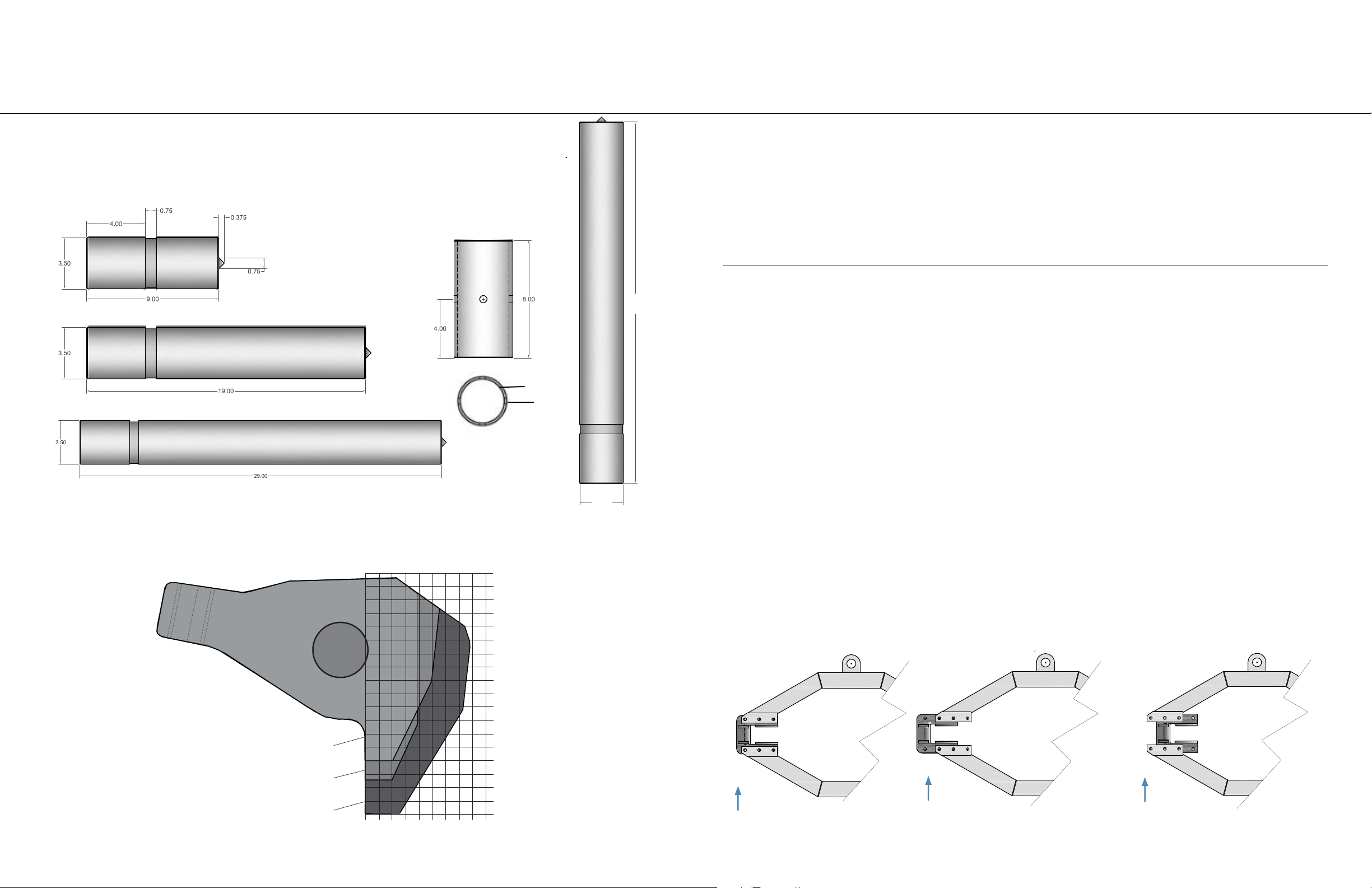
Pushers | Jaw Tips
POSI LOCK® 100-TON & 200-TON
Hydraulic Puller Systems
Assembly | Adjustments
PUSHERS:
Included with the 100-Ton pullers are THREE pushers and a coupler. String 2 pushers together to increase the reach
of the ram. Using a variety of combinations may be necessary to complete the pull of a deeply set gear or bearing.
Included with the 200-Ton puller are FOUR pushers. The diameters are 4 inches. The 200-T does not include a
coupler.
Coupler
*Not included with the
200-Ton.
HT-1164
HT-1163
HT-1162
3.52
ASSEMBLY:
1. Ensure that shipping crate rmly rests on level ground in upright position.
2. Open small side panel and conrm that puller is resting rmly in upright position in the create.
3. Remove remainder of plywood.
4. Inspect puller for any damage that may have been caused by shipping.
5. Save bolts that were used to brace the cart. These will be used for securing the included cart wheels to the cart.
6. Inspect hoses for proper ratings. Connect the 10,000 psi hose to the port marked “10,000 psi only” on the puller and the
pressurized port on the pump. Connect hose with the lower pressure rating to the return port on puller and pump.
7. Fill reservoir of pump with pump manufacturer specied oil. See pump or cylinder manual for details.
ADJUSTMENTS:
RAISING THE PULLER:
39.00
4
1. Place cylinder control valve lever in “Hoist Oil Supply” position.
2. Raise puller by placing remote jog switch in “On” position and opening the puller hoist vertical control valve.
3. Release remote jog switch. Close vertical control valve after reaching desired height.
LOWERING THE PULLER:
1. Place cylinder control valve lever in “Hoist Lower” position.
2. Lower puller by turning puller hoist vertical control valve counterclockwise.
3. Close vertical control valve after reaching desired height.
NOTE:
HOIST TRAVEL SPEED:
The restrictor valve, located at the top of the hoist cylinder, is used to control the rate of puller descent. This valve should be set at
the desired rate and locked in place using the nut on the valve shaft.
JAW TIPS:
3 jaw tip sizes are available for 100 and 200 Ton puller models.
• HT-1180: standard with all models.
• HT-1180A: optional, for operations with limited space constraints.
• HT-1180S: optional, for operations with limited space constraints.
*Tip widths are 3 inches thick.
HT-1180S
HT-1180A
HT-1180*
0.0
0.5
1.0
1.5
2.0
2.5
3.0
3.5
4.0
9.0
4.5
8.5
8.0
7.5
7.0
6.5
6.0
5.5
5.0
4.5
4.0
3.5
3.0
2.5
2.0
1.5
1.0
0.5
0.0 in.
4
*Included with
200-Ton only.
An appropriate starting point is one full turn from the closed position. This valve is a one-way restrictor only and does not aect
the rate at which the puller is raised.
CHANGING THE JAW SPREAD:
If opening/closing the jaws using the standard cage setting does not provide enough spread or does not provide enough closure,
use the following adjustments to achieve the maximum and minimum spreads.
1. Support the jaws.
2. Remove 6 cap screws, lock washers and nuts on 1 jaw guide at a time.
3. Slide jaw guide inward/outward on cage 1 bolt hole.
4. Replace 4 cap screws, lock washer, and nuts and tighten appropriately.
5. Reverse this process to return to standard jaw spread.
Default jaw guide position
when puller is shipped.
Jaw guide moved 1 bolt hole
OUT to increase spread.
Jaw guide moved 1 bolt hole
IN to decrease spread.
54
POSI LOCK® 100-TON & 200-TON
!
!
POSI LOCK® 100-TON & 200-TON
Hydraulic Puller Systems
Adjustments (continued) | Removing puller from cart
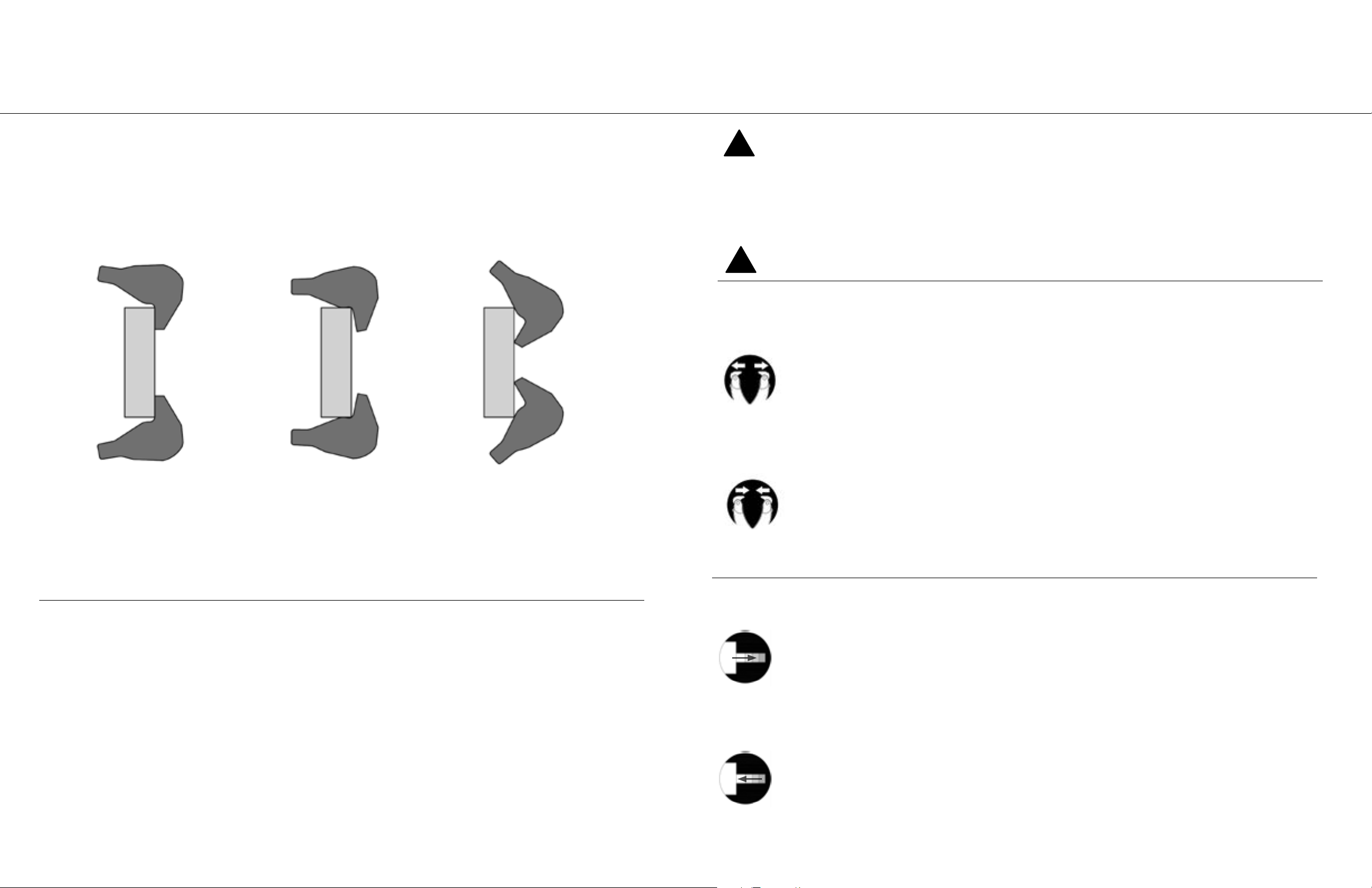
ADJUSTING JAW TIPS:
1. Adjust jaw tips by turning 1 ¼” cap screw.
NOTE: Always use maximum pulling surface of jaw. To angle tip inward, turn cap screw clockwise. To angle tip outward, turn cap
screw counterclockwise. Before pulling, always make certain machined caps are properly tted to curved surface.
Correct Alignment
Incorrect Incorrect
Hydraulic Puller Systems
Set-up | Pulling an object
OPERATION IMPORTANT: Hydraulic power is one of the safest methods for applying force when used correctly. Be sure to
read all instructions, warnings and cautions carefully.
Follow all safety precautions to avoid personal injury or property damage during system operation. Posi Lock cannot be responsible
for damage or injury resulting from unsafe use of product, lack of maintenance or incorrect product and/or system operation.
It is important that the operator has a full understanding of all the instructions, warnings, cautions and safety regulations before
starting to operate equipment. When in doubt contact Posi Lock at +1-701-797-2600.
MAINTENANCE: Always clean the puller after use and store in a clean, dry place.
SET-UP:
1. Transport the puller by use of the puller cart of forklift.
2. Line the puller up to the workpiece.
3. Open the jaws.
OPENING THE JAWS:
I. Place cylinder control valve lever in “Oil Supply” position.
II. Place cage control lever in “Jaw Open” position and activate pump by pushing remote switch to the “On”
position to open jaws to the desired spread.
ADJUSTING SLIDE ROLLERS:
1. Lower slide and puller assembly until it rests solidly on base.
2. Loosen 5/8” hex bolt.
3. Move roller using eye bolts on each side of roller.
4. Adjust roller until equal spacing is obtained between mast and slide tube on both roller side and opposite side.
5. Tighten locking nut on eye bolt.
6. Tighten 5/8” hex bolt.
100-TON:
REMOVING PULLER FROM THE CART:
1. Support puller weight using lifting brackets provided.
2. Close puller hoist vertical control valve.
3. Disconnect puller hoist hose coupler at control panel.
4. Remove 2 of the ½” bolts which fasten locking plate to the puller lift bracket.
5. Remove puller from cart by rotating cart while keeping puller stationary.
200-TON:
REMOVING PULLER FROM THE CART:
1. Support puller weight using lifting brackets provided.
2. Close puller hoist vertical control valve.
3. Disconnect puller hoist hose coupler at control panel.
4. On each slide, remove the top and bottom ½” bolts. Do this on both the left and right slide, removing a total of 4 bolts.
5. While keeping the puller supported and balanced, remove from the cart by moving the puller forward.
4. Position the workpiece to be removed in between the jaws.
5. Continue to adjust the height until the workpiece and extending cylinder are aligned. See RAISING THE PULLER on page 3.
6. Close the jaws.
CLOSING THE JAWS:
I. Place cylinder control valve lever in “Oil Supply” position.
II. Place cage control lever in “Jaw Closed” position and activate pump by pushing remote switch to the “On”
position to close jaws to the desired spread or for clamping.
7. Adjust the jaw tips appropriately. See ADJUSTING JAW TIPS on page 4.
PULLING AN OBJECT:
1. Extend the cylinder ram towards the workpiece until there is contact.
EXTENDING CYLINDER:
I. Place cylinder control valve in “Extend” position.
II. Activate pump with jog switch.
2. Continue to extend the ram. The workpiece will begin to move gradually o the shaft.
3. Retract the cylinder.
4. Completely remove the workpiece.
RETRACTING CYLINDER:
I. Place cylinder control valve in the “Retract” position.
II. Activate pump with jog switch.
NOTE: On a single acting cylinder the cylinder ram will retract without activating the pump.
76
POSI LOCK® 100-TON & 200-TON
POSI LOCK® 100-TON & 200-TON
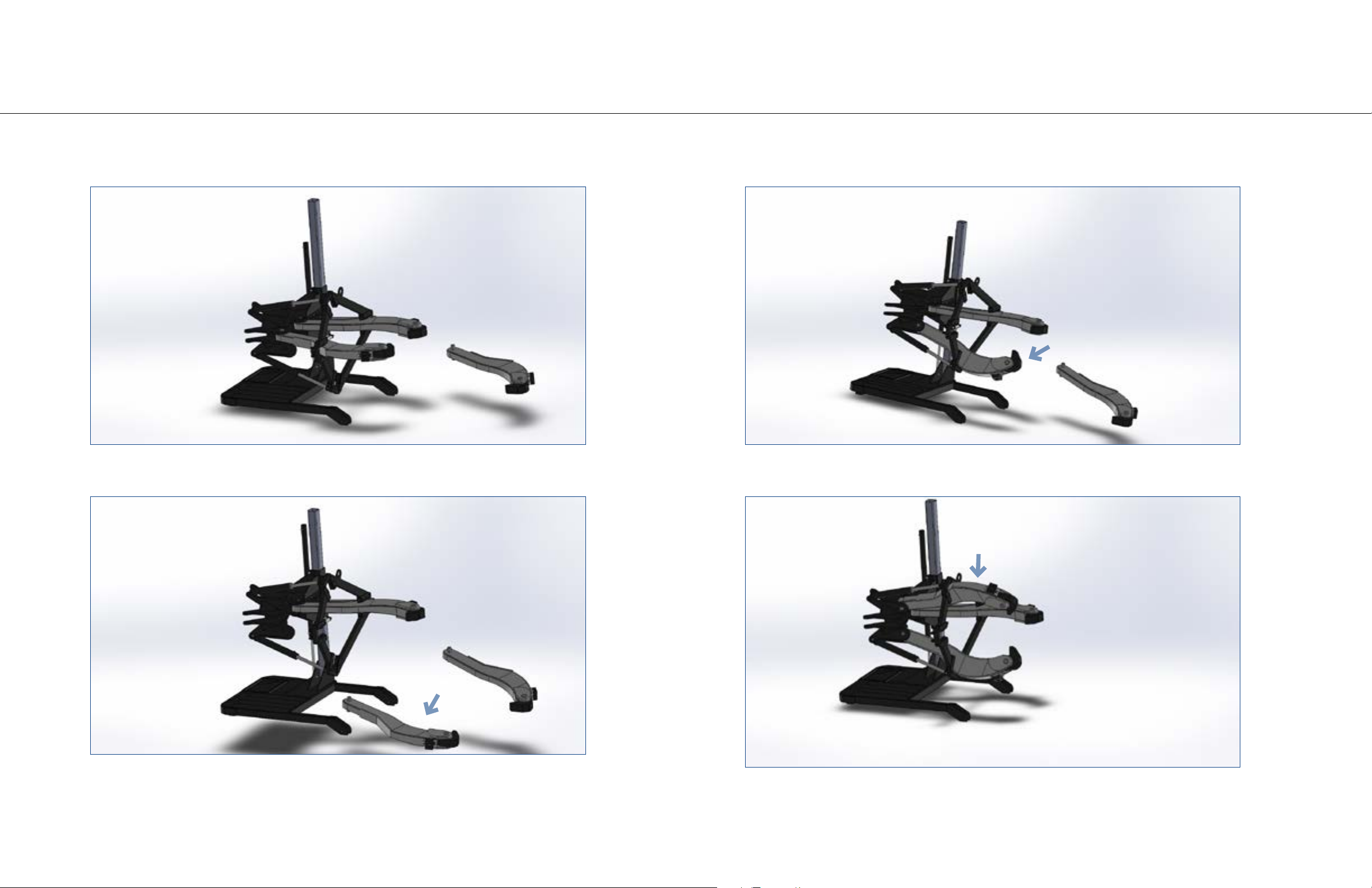
Hydraulic Puller Systems
PH-123T Transformation
1. Starting in a 2-jaw conguration, move the cage cylinder from the 2-jaw position to the 3-jaw position.
Hydraulic Puller Systems
PH-123T Transformation (continued)
3. Place the jaw into the lower 3-jaw position.
2. Remove the jaw on the left from the 2-jaw position.
4. Place jaw from the left 2-jaw position into upper 3-jaw position to complete the transformation.
98

100 Ton Spread Range Diagram
POSI LOCK® 100-TON & 200-TON
POSI LOCK® 100-TON & 200-TON
Hydraulic Puller Systems
Spread Range
SPREAD RANGE DIAGRAM:
Use the diagram to determine the limitations of the jaw-opening. Spread ranges apply to all POSI LOCK 100-Ton and 200-Ton
hydraulic puller systems. Gears, pulleys, wheels, sleeves, and other press t parts must t within these limitations.
Hydraulic Puller Systems
Schematics | PH-100T | PH-123T
1110

POSI LOCK® 100-TON & 200-TON
POSI LOCK® 100-TON & 200-TON
Hydraulic Puller Systems
Hydraulic Fittings | PH-100T | PH123T
Hydraulic Fittings for 3 Jaw 100-Ton Pullers
SYM PART # DESC. QTY
A H T -112 3
B H T-112 4 3/8 Male NPTF x 3/8 Male 37 NPTF 1
C HT-112 5 3/8 Male NPTF x 3/8 Female NPTF 3
D H T -112 6 3/8 Female NPTF Tee 1
E H T-113 4
G H T -112 8
H HT-112 9
I H T -1113 3/8 Male NPTF x 3/8 Female NPTF 2000 PSI Relief 1
J H T -113 0 3/8 Male NPTF x 3/8 Female NPTF x 3/8 Female NPTF 2
K HT-1131
N HT-10 01 3/8 Male NPTF x 3/8 Female NPTF x 3/8 Female NPTF 1
O HT-1002 3/8 Male NPTF x 3/8 Male NPTF 1
P HT-1003
Q HT-10 0 4 3/8 Male NPTF x 3/8 Female NPTF 1
R H T-1 011 3/8 Female NPTF x 3/8 Female NPTF 1
S H T-1191 3/8 Male NPTF x 3/8 Male Barbed 2
U H T-115 4 3/8 Male NPFT Vent 1
V H T-10 06 3/8 Female NPTF x 3/4 BOSS 1
W HT-1013
X HT-1014 3/8 Male NPTF x 3/8 Female NPTF 2
Y H T -113 4 A
Z H T-113 4 B
3/8 Male NPTF x 3/8 Male 37
3/8 Male NPTF x 1/4 Male 37
3/8 Male NPTF x 3/8 Female 37
3/8 Male 37
3/8 Male NPTF x 3/8 37
3/8 Male NPTF x 3/8 37
3/8 Male 37
3/8 Male NPTF x 1/4 Male 37
3/8 Male NPTF x 1/4 Male 37
˚
˚
˚ Cross
˚
˚
˚ x 3/8 Female 37˚
˚
˚
Hydraulic Puller Systems
Hydraulic Hoses and Components | PH-100T | PH123T
Hydraulic Hoses and Components for 3 Jaw 100-Ton Pullers
SYM PART # DESC. QTY
5
7
˚
1
1
2
4
3
2
1
AA PH10010 100-Ton Cylinder 1
BB H T-110 3 3-Ton Cylinder 3
CC HT-VC4 4-Way Valve 1
DD H T-1114 3 Section Flow Divider 1
EE FHCH-38M Male Coupler 3
FF HT-VC20
GG HT-V82
4-Way Closed Center Valve
Needle Valve
HH H T -112 1 1-Way Valve 1
II H T-1117 Hoist Cylinder 1
KK HT-GA3 Gauge Adaptor 1
LL PGB254TLM 10,000 PSI Gauge 1
MM PH-2022 Pump 1
NN H T-113 5 16” 10,000 PSI Hose 1
QQ H T -1139 33” Hose 2*
RR FHCH-38F Female Coupler 3
SS H T-114 0 44” Hose 1**
TT H T-1141 21” Hose 1
UU H T-1142 A 15” H os e 2
WW HT-1005 30” Hose 1
AA1 PH-927 10’ 10,000 PSI Hose 1
AA2 H T-119 0 10’ Return Hose 1
1
1
ST-1 HT-ST1 Steel Line 1
ST-2 HT-ST2 Steel Line 1
ST-3 HT-ST3 Steel Line 1
ST-4 HT-ST4 Steel Line 1
SPECIAL NOTES:
* 1- 33” hose is included for the 2/3 jaw combination puller.
** 2- 44” hoses are included with the 2/3 jaw combination puller.
1312

POSI LOCK® 100-TON & 200-TON
POSI LOCK® 100-TON & 200-TON
Hydraulic Puller Systems
Schematics | PH-102T
Hydraulic Puller Systems
Hydraulic Fittings, Hoses and Components | PH-102T
Hydraulic Fittings for 2 Jaw Pullers
SYM PART # DESC. QTY
A H T -112 3
B H T-112 4 3/8 Male NPTF x 3/8 Male 37 NPTF 1
C HT-112 5 3/8 Male NPTF x 3/8 Female NPTF 3
D H T -112 6 3/8 Female NPTF Tee 1
E H T-113 4
F H T-112 7
I H T -1113 3/8 Male NPTF x 3/8 Female NPTF 2000 PSI Relief 1
J H T -113 0 3/8 Male NPTF x 3/8 Female NPTF x 3/8 Female NPTF 2
K HT-1131
N H T-10 01 3/8 Male NPTF x 3/8 Female NPTF x 3/8 Female NPTF 1
O HT-1002 3/8 Male NPTF x 3/8 Male NPTF 1
P HT-1003
3/8 Male 37
3/8 Male NPTF x 3/8 Male 37
3/8 Male NPTF x 1/4 Male 37
˚x 3/8 Female 37 ˚ x 3/8 Male 37˚
3/8 Male NPTF x 3/8 37
3/8 Male NPTF x 3/8 37
˚
˚
˚
˚
5
7
1
3
1
Q HT-10 0 4 3/8 Male NPTF x 3/8 Female NPTF 1
R H T-1 011 3/8 Female NPTF x 3/8 Female NPTF 1
S H T-1191 3/8 Male NPTF x 3/8 Male Barbed 2
U H T-115 4 3/8 Male NPFT Vent 1
V H T-10 06 3/8 Female NPTF x 3/4 BOSS 1
X HT-1014 3/8 Male NPTF x 3/8 Female NPTF 2
Y H T -113 4 A
Z H T-113 4 B
3/8 Male NPTF x 1/4 Male 37
3/8 Male NPTF x 1/4 Male 37
˚
˚
2
1
1514

POSI LOCK® 100-TON & 200-TON
POSI LOCK® 100-TON & 200-TON
Hydraulic Puller Systems
Hydraulic Fittings, Hoses and Components | 102T
Hydraulic Hoses and Components for 2 Jaw 100-Ton Pullers
SYM PART # DESC. QTY
AA PH10010 100 -To n Cylinder 1
BB H T-110 3 3-Ton Cylinder 2
CC HT-VC4
EE FHCH-38M Male Coupler 3
FF HT-VC20
GG HT-V82
HH H T -112 1 1-Way Valve 1
II H T-1117 Hoist Cylinder 1
JJ H T-118 7 2 Section Flow Divider 1
KK HT-GA3 Gauge Adaptor 1
LL PGB254TLM 10,000 PSI Gauge 1
4-Way Closed Center Valve
4-Way Valve
Needle Valve
Hydraulic Puller Systems
Schematics | PH-200T
1
1
1
MM PH-2022 Pump 1
NN H T-113 5 16” 10,000 PSI Hose 1
OO H T -1136 12 1/4” Hose 2
RR FHCH-38F Female Coupler 3
WW HT-1005 30” Hose 1
XX H T-113 9 33” Hose 2
AA1 PH-927 10’ 10,000 PSI Hose 1
AA2 H T-119 0 10’ Return Hose 1
ST-1 HT-ST1 Steel Line 1
ST-2 HT-ST2 Steel Line 1
ST-3 HT-ST3 Steel Line 1
ST-4 HT-ST4 Steel Line 1
1716

POSI LOCK® 100-TON & 200-TON
POSI LOCK® 100-TON & 200-TON
Hydraulic Puller Systems
Hydraulic Fittings | PH-200T
Hydraulic Fittings for 200-Ton Puller
SYM PART # DESC. QTY
A H T -112 3
B H T-112 4 3/8 Male NPTF x 3/8 Male 37 NPTF 1
C HT-112 5 3/8 Male NPTF x 3/8 Female NPTF 3
D H T -112 6 3/8 Female NPTF Tee 1
E H T-113 4
F H T-112 7
I H T -1113 3/8 Male NPTF x 3/8 Female NPTF 2000 PSI Relief 1
J H T -113 0 3/8 Male NPTF x 3/8 Female NPTF x 3/8 Female NPTF 3
K HT-1131
N H T-10 01 3/8 Male NPTF x 3/8 Female NPTF x 3/8 Female NPTF 5
P HT-1003
Q HT-10 0 4 3/8 Male NPTF x 3/8 Female NPTF 1
R H T-1 011 3/8 Female NPTF x 3/8 Female NPTF 1
S H T-1191 3/8 Male NPTF x 3/8 Male Barbed 2
U H T-115 4 3/8 Male NPFT Vent 2
V H T-10 06 3/8 Female NPTF x 3/4 BOSS 1
X HT-1014 3/8 Male NPTF x 3/8 Female NPTF 1
Y H T -113 4 A
3/8 Male 37
3/8 Male NPTF x 3/8 Male 37
3/8 Male NPTF x 1/4 Male 37
˚x 3/8 Female 37 ˚ x 3/8 Male 37˚
3/8 Male NPTF x 3/8 37
3/8 Male NPTF x 3/8 37
3/8 Male NPTF x 1/4 Male 37
˚
˚
˚
˚
˚
15
10
Hydraulic Puller Systems
Hydraulic Hoses and Components | PH-200T
Hydraulic Hoses and Components for 200-Ton Puller
SYM PART # DESC. QTY
AA PH20 013 200-Ton Cylinder D/A 1
BB H T -110 3 3-Ton Cylinder 4
CC HT-VC4
EE FHCH-38M Male Coupler 3
1
FF HT-VC20
4-Way Closed Center Valve
GG HT-V82
II HT -1117 Hoist Cylinder 2
3
JJ HT-118 7 2 Section Flow Divider 2
KK HT-GA3 Gauge Adaptor 1
5
LL PGB254TLM 10,000 PSI Gauge 1
MM PH-2022 Pump 1
NN H T -113 5 16” 10,000 PSI Hose 2
OO H T -113 6 12 1/4” Hose 4
RR FHCH-38F Female Coupler 3
SS H T - 114 0 46” Hose 2
3
XX H T-113 9 33” Hose 3
4-Way Valve
Needle Valve
2
1
1
Z H T-113 4 B
3/8 Male NPTF x 1/4 Male 37
˚
1
AA1 PH-927 10’ 10,000 PSI Hose 1
AA2 H T- 119 0 10’ Return Hose 1
AA3 H T-113 5 - 7 23” 10,000 PSI Hose 1
AA4 HT-34 34” Hose with 3” Elbow 1
AA5 HT-78 78” Hose 1
ST-1 HT-ST1 Steel Line 1
ST-2 HT-ST2 Steel Line 1
ST-3 HT-ST3 Steel Line 1
ST-4 HT-ST4 Steel Line 11
1918

POSI LOCK® 100-TON & 200-TON
POSI LOCK® 100-TON & 200-TON
Hydraulic Puller Systems
Parts List
QUANTITY
PART # DESC. 10 0T/123T 102T 200T
HT-1001 Fitting N 6 fp-fp-mp 1 1 5
HT-1002 Fitting O 6MP-6MP90 1 1 -
HT-1003 Fitting P 8MJ-6MP 4 1 5
HT-1004 Fitting Q 6MP-6FP45 1 1 -
HT-1005 Hose WW-115 30" 1 1 -
HT-1006 Fitting 3/4" male 3/8 FP 1 - 1
HT-1011 Fitting R 6FP-6FP 1 1 1
HT-1013 Fitting 1/2" MJ X1/2 FJ80 3 - -
HT-1014 Fitting 13/8" MP X 3/8" FP 2 2 1
HT-1015 5/8" hex lock nut 4 4 4
HT-1016 1/2" hex nut 29 23 32
HT-1017 1/2" lock washer 25 19 30
HT-1018 3/8" hex nut 12 8 -
HT-1019 3/8" lock washer 12 12 -
HT-1020 1/4" lock washer 4 4 6
HT-1021 1/4" at washer 4 4 -
Hydraulic Puller Systems
Parts List (continued)
QUANTITY
PART # DESC. 10 0T/123T 102T 200T
H T -110 6 A Pin (1" X 4-1/8") 4 3 6
HT-
110 6 A -2 3
H T -110 6 B Pin (1" X 6-1/2") 1 1 -
H T -110 6 C Pin (1"X 5-1/4") 2 1 -
H T -110 7 1" external snap ring 14 10 16
H T -1111 Cart 1 1 -
H T -1111A Mast 1 1 -
H T -1111B Slide (puller holder) 1 1 -
H T -1113 Relief valve #RV-38-K-2000 1 - 1
H T -1114 Flow divider 3 jaw and combo 1 1 -
H T -1117 Mast Cylinder #1540 1 1 2
H T -1117B Roller adjuster 4 4 8
H T -1118 B Bushing 2 2 4
H T -1119B Roller 2 2 4
H T -112 1 Flow control valve 1 1 -
H T -112 3 Fitting A 6mp-8mj90 5 5 15
Pin (1" X 4-1/8") not plated - - 1
HT-1022 3/8" hex Lock nut 4 4 8
HT-1023 3/8" at washer 4 4 -
HT-1024 5/16"X1 hex head cap screw - 4 12
HT-1025 5/16" hex nut - 4 8
HT-1026 5/16" lock washer - 4 12
HT-1027 5/16" at washer - 4 -
HT-1028 5/8"X6" hex cap screw grade 8 2 2 4
HT-1051 1/4"X3/4" hex cap screw 4 4 6
HT-1052 1/2"X 1-1/2" hex cap screw 3 3 18
HT-1053 1/2"X1/4" sock head cap screw 2 2 -
HT-1054 1/2X1/2 Socket set screw 1 1 1
HT-1057 Decal (hoist oil) 1 1 1
HT-1058 Self drilling screws 8 6 8
H T -110 3 3 -Ton cylinder # 2016 3 2 4
H T -110 4 Jaw 3 2 4
H T -110 5 Jaw head for 3 jaw 1 - -
H T -112 4 Fitting B 6mp-fp90 1 1 1
H T -112 5 Fitting C 6mp-6mp 3 3 3
H T -112 6 Fitting D 6fpt 1 1 1
H T -112 7 Fitting F 8fjx-8mj-8mj 0 1 1
H T -112 8 Fitting G 6mp-8fjx90 1 - -
H T -112 9 Fitting H 8mj-cross 1 - -
H T -113 0 Fitting J 6fp-6mp-6fp 2 2 3
HT-1131 Fitting K 6mp-8mj45 2 3 3
H T -113 4 Fitting E 6mp-6mj90 7 7 10
H T -113 4 A Straight tting 6mp-6mj 2 2 2
H T -113 4 B 45 degree tting 6mp-6mj45 1 1 2
H T -113 5 Hose NN-101 15" high jack 1 1 -
H T -113 5 - 7 Hose NN-101-23" high jack - - 2
H T -113 5 -
15
H T -113 6 OO hose-103 12.25" - 1 4
H T -113 9 XX-112 33" hose 2 2 3
Hose AA6-101-32" high jack - - 1
2120

POSI LOCK® 100-TON & 200-TON
POSI LOCK® 100-TON & 200-TON
Hydraulic Puller Systems
Parts List (continued)
QUANTITY
PART # DESC. 100 T/123 T 102T 200T
H T -1142 A Hose YY-116 15" 2 - -
H T -114 4 Decal 100-Ton 1 - -
H T -1145 Decal, 100-Ton cyl/sup oil 1 1 1
H T -1146 Decal, lift area 2 2 4
H T -1147 Decal, 10,000 PSI 1 1 1
H T -1148 Decal, jaw area 2 2 4
H T -1149 Decal, return oil 1 1 1
H T -115 0 Decal, 100-Ton 2 jaw - 1 -
H T -115 3 Control cover 1 1 1
HT-1154 3/8" male vent #4450K3 1 1 2
H T -115 5 Caster 2 2 -
H T -115 6 Wheel 2 2 -
Hydraulic Puller Systems
Parts List (continued)
QUANTITY
PART # DESC. 10 0 T/123T 102T 200T
H T -1187 Flow divider for 2 jaw - 1 2
HT-1190 10' return hose 1 1 1
H T -1191 Barbed male hose end - - 2
H T -1199 Adapter for pusher 1 1 -
HT-1205 Jaw head for 2 jaw - 1 -
HT-120 6 Cage rail w/ eyelet (2 jaw) - 1 -
HT-1207 Cage rail w/o eyelet (2 jaw) - 1 -
HT-120 8 Coupler for pusher 1 1 -
HT-20 013 200 -Ton cylinder D/A - - 1
HT-2005A Hose AA4 - 34" with 3" elbow - - 1
HT-2005B Hose AA5 - 78" - - 1
HT-2159 200-Ton jaw guide - - 2
H T -115 8 Cage rail w/o eyelet 3-2/3jaw 2 - -
H T -115 9 Jaw guide 3 2 -
H T -1160 A Pin (1-1/2"X 5 1/4" 2 1 -
H T -1160 - B Pin (1-1/2" X 6") 1 1 -
H T -1161 1-1/2" external snap ring 6 4 4
H T -1162 Pusher 3-1/2" X 29" 1 1 -
H T -1163 Pusher 3-1/2" X 19" 1 1 -
H T -116 4 Pusher 3-1/2"X 9" 1 1 -
H T -1165 1/2" X 4" hex cap screw 4 4 -
H T -1166 3/8"X 3" hex cap screw 8 8 -
H T -1167 Plate, Puller Lock 1 1 -
H T -1168 Cage rail for Combo 2/3 only 2 - -
H T -1170 Control valve mounting bracket 1 1 1
HT-1171 1/2" X 2-1/2" hex cap screw 18 12 -
H T -1172 Cage rail w/eyelet 3-2/3 jaw 1 - -
H T -1175 5/8" X 4" hex cap screw 2 2 -
H T -1176 Decal, hoist valve/oil 1 1 1
H T -1178 Decal, cage control 1 1 1
H T -118 0 Jaw end 3 2 4
H T -1181 Pin (2" X 6") 3 2 -
H T -1182 2" external snap ring 6 4 4
HT-2160A Pin 1 1/2 x 13 13/16 - - 2
HT-2162 200-Ton pusher 29" - - 1
HT-2163 200-Ton pusher 19" - - 1
HT-216 4 200-Ton pusher 9" - - 1
HT-2181 Pin 2 x 12 3/16 - - 2
HT-2199 Adaptor for pushers - - 1
HT-2204 3-Ton cylinder spacer - - 2
HT-2204-
1
HT-2206 200-Ton upper cage - - 1
HT-2207 200-Ton lower cage - - 1
HT-2210 Jaw guide spacer - - 8
HT-2405 Jaw head for 200-Ton puller - - 1
HT-
9306K34
HT-2150 Decal, 200-Ton 4 jaw - - 1
HT-2171 1/2" x 3 1/4' hex head cap SCR - - 12
UW16 1" Dia. hardened washer - - 2
HT-1029 1" x 1 1/4" hex head cap SCR - - 2
HT-1030 1" lock washer - - 2
HT-
2170DA
HT-2106B Pin 1 x 12 1/2" - - 2
3-Ton cylinder spacer - - 4
Bumper stops - - 2
Control valve nounting bracket - - 1
2322

POSI LOCK® 100-TON & 200-TON
FLOW DIVIDERS
Delta Power Company
4484 Boeing Drive - Rockford, IL 61109
etc.
POSI LOCK® 100-TON & 200-TON
PGB254TLM Gauge 1 1 1
FHCH-38M Male Coupler 3 3 -
Hydraulic Puller Systems
Parts List (continued)
QUANTITY
PART # DESC. 10 0T/123T 102T 200T
H T -2111A R 200-Ton Mast - - 1
H T -2112 200-Ton Puller Slide - - 2
HT-ST1 Steel Tube 1 1 1
HT-ST2 Steel Tube 1 1 1
HT-ST3 Steel Tube 1 1 1
HT-ST4 Steel Tube - 1 1
HT-ST5 Steel Tube 1 1 -
HT-VC4 4-Way Valve 1 1 2
HT-CH604 Male Coupler - - 3
HT-VC20 4-Way Closed Center Valve 1 1 1
HT-V82 Needle Valve 1 1 1
HT-CR400 Female Coupler - - 3
PH -10 010 100 -Ton Cylin der 1 1 -
PH-2022 Electric Pump 1 1
HT-GA3 Gauge Adapter 1 1 1
PH - 411 Dust Cap 3 3 -
PH-927 Hose 10' 1 - 1
FHCH-38F Female Coupler 3 3 -
200-Ton Hydraulic Pump - - 1
Hydraulic Puller Systems
Flow Dividers
Delta Power Rotary Flow Divider, Positive Displacement
Delta Series P geared flow dividers, accurately divide flow from a single hydraulic
source into two or more equal or proportionate circuits. In like manner, the input
pressure required will be proportional to levels of flow/pressure out of the flow divider,
rather than at the highest pressure level, thereby saving what would normally be
wasted energy. Proven design, stable material selection and precision machining are
the Delta keys to reliable performance you can depend on in a variety of applications.
Application Suggestions
1. For greatest efficiency and accuracy, flow dividers should be used at near
maximum rated inlet gallonage. For quieter operations, lowered RPM should
be considered.
2. Maximum (3500) and minimum 500 RPM; inlet pressure ratings and differential
pressure ratings should be followed.
3. Provide over-pressure protection (relief valves) in each circuit.
4. When designing flow dividers into a static circuit, remember that they are
dynamic devices which do nothing while static.
5. Use SAE 10 through SAE 30 industrial petroleum-based hydraulic oil with 200
SSU viscosity; filter to 25 microns.
6. Do not use teflon tape in installation. Use plastic pipe sealant with NPTF ports.
• High-strength permanent mold cast iron housing
• Precision needle bearings
• Precise machined trapping relief grooves provide
constant filling and discharging to assure quiet
operation and maximum bearing life.
• O-ring seals between sections (Buna-N)
Where one pump operates a
number of hydraulic motors: car
wash systems lubrication systems
(multiple point), hydraulic motor
driven machines, (harvesting
machinery, etc.)
Where two or more cylinders must
be synchronized: lift platforms,
scaffolds, presses.
Where main pump pressure must be
intensified in one circuit of multiple
circuit machinery, such as waste
compactors and other hi-lo
applications.
Where two or more circuits must be
controlled independently at different
pressures: presses, machine tools,
2524

FLOW DIVIDERS
Delta Power Company
4484 Boeing Drive - Rockford, IL 61109
i
FLOW DIVIDERS
Delta Power Company
4484 Boeing Drive - Rockford, IL 61109
POSI LOCK® 100-TON & 200-TON
POSI LOCK® 100-TON & 200-TON
Hydraulic Puller Systems
Flow Dividers
Application Data
The Delta flow divider is a positive displacement flow dividing or proportioning apparatus. It will divide the flow from one
source into two or more equal or proportionate circuits, and intensify or reduce the pressure level as required. Note that
these flow dividers will operate in reverse in a combine mode, but in that mode, the accuracy likely would be significantly
reduced.
In its basic configuration, the unit consists of a number of inter coupled gear type hydraulic pump motors. Each section
must be capable of performing the pumping or motoring function. The section have a common inlet and separate outlets.
Fluid from a prime source, such as pump, supplies the motive power to the flow divider. No energy is added to the fluid in
the device, although each outlet may have an energy level difference than any other section. When the sections are of like
size, the function is to divide the total flow into equal increments of flow, and when the sections are of unlike size, the
function is to divide the flow into proportionate increments relative to the chosen geometric displacements.
Since the flow divider is a positive displacement machine, it will accomplish its function over a wide range of pressure of
viscosity differentials. Nevertheless, certain limits are imposed due to slip characteristics and torque losses in the
machine. Therefore, the performance criteria in this paper will be developed around a unit of average tolerance allowance.
The data, so derived, will be averaged. Be aware that these units can require a certain amount of break-away pressure. It
is recommended that operation at low pressures (< 100 PSI) is not attempted without consultation with the factory.
General Relationships
In any unit, neglecting any losses, there exists the relationship that
= Q1+ Q2 + …. Qn;
Q
i
Where Q
is the flow into the unit and Q1, Q2 and Qn are the displacements out of each section. Since no energy is added
i
and if none were lost, it follows that
= P1Q1 + P2Q2 + …. PnQn;
P
iQi
Where P
is the pressure into the unit and P1, P2 and Pn are the pressure levels out of each section.
i
In a unit consisting of any number of/or sizes of sections
+ P2Q2 + …. PnQn
P
=
P
i
1Q1
Q
i
In any actual case, the above theoretical observations must be corrected to encompass the pressure drop and slip losses
in the flow divider. The pressure drop is primarily a function of the amount of fluid and viscosity. At the usual viscosities
(100 to 300 SSU) encountered in hydraulic systems, the pressure drop ∆P
, can be approximated by the relationship,
p
where n is the number of sections,
6Q
i
∆P
≅ +25
P
n
Since the flow divider itself is a parallel circuit, the actual pressure P
into the unit is
ia
+ P2Q2 + …. PnQn
P
1Q1
P
≅ + ∆P
ia
Q
P
Hydraulic Puller Systems
Flow Dividers
Slip is a function of the viscosity, pressure differential and clearance and can be estimated from the following chart:
Model
PM2 .00047 .03 2.0
PM6 .00137 .04 5.5
P21 .00178 .06 7.6
P23 .00304 .07 12
P25 .00425 .08 17
P26 .00531 .10 20
P27 .00633 .11 25
P43 .01020 .15 35
P47 .01690 .22 50
The slip function increases or decreases the flow from a section, dependent on whether the pressure differential is
positive or negative across that section.
The performance of a system would be determined in the following manner.
1. Determine the size of the sections that will best give the required flow and pressure. The displacement from each
section will be the fractional proportion of the sectional displacement versus the sum of the displacements of all
the sections. That fraction multiplied by the input flow gives output displaced by each section.
6Q
2. Determine ∆P
from ∆PP ≅ +25
p
n
P
3. Determine P
from Pia ≅ +∆PP
ia
Q
4. Determine the pressure differential ∆P
from this value, determine the slips S
5. Determine Q
, Q2a, Qna from Q1a = Q1 + S1, etc.
1a
The foregoing description is intended as an aid in determining the results of a flow divider system. Any specific application
should not be undertaken without independent study, evaluation and testing for suitability. Exceeding the specifications
could result in equipment malfunction, property damage, serious injury or death.
Displacement
Gal./Rev./Sect.
i
1 Q1 + P2 Q2
…. Pn Qn
1
1, ∆P2, ∆Pn
, S2, Sn.
1
Slip/100 PSI
(GPM)
Max. Flow/Sect.
(GPM)
across the individual section where ∆P1 = ∆P
ia
- ∆P
etc., and
1,
2726

FLOW DIVIDERS
Delta Power Company
4484 Boeing Drive - Rockford, IL 61109
P Series, Equal Flow Two Sections
-
FLOW DIVIDERS
Delta Power Company
4484 Boeing Drive - Rockford, IL 61109
-
POSI LOCK® 100-TON & 200-TON
POSI LOCK® 100-TON & 200-TON
Hydraulic Puller Systems
Flow Dividers
Equal flow two-section units divide flow from a common pump source into separate flows of equal proportion. Both gear
sets are assembled to a common shaft.
PM2 & PM6
P23 & P27
Hydraulic Puller Systems
Flow Dividers
P Series, Equal Flow Multi-Sections
Equal flow multi-section units consist of several identical, individual sections coupled together to divide a flow from a
common pump source into three or more equal flows. Each set of gear and shaft assemblies are individually supported in
needle bearings.
PPM2
P23-(57-60) & P27-(57-60)
P43 & P47
MODEL NUMBER
OF
SECTIONS
PM2 2 3.5 0.00047 0.026 2500 2000 13-17 3.83 1500
PM6 2 9.5 0.00137 0.038 2000 1500 13-17 4.72 1000
P23 2 21.0 0.00304 0.068 2000 1500 24-31 5.32 1000
P27 2 44.0 0.00633 0.113 2000 1500 24-31 6.86 1000
P43 2 70.0 0.01020 0.135 2000 1500 24-31 7.75 1000
P47 2 100.0 0.01690 0.210 2000 1500 24-31 9.25 1000
TOTAL MAX.
INLET
(GPM)
0 PSI DISP.
PER SECT.
GAL./REV,
SLIP
GPM/100 PSI
MAXIMUM
INTERMITTENT
PSI
MAXIMUM
CONTINUOUS
PSI
BOLT
TORQUE Ft.
Lb.
A MAX. DIFF.
BETWEEN
SECT. (PSI)
MODEL NUMBER
OF
SECTIONS
PPM2 4 7.0 0.00047 0.026 2000 1500 13-17 - - - - 1000
P23-60 3 31.5 0.00304 0.068 2000 1500 24-31 0.715 2.39 2.56 8.83 1000
P23-59 4 42.0 0.00304 0.068 2000 1500 24-31 0.715 2.39 2.56 11.39 1000
P23-58 5 52.5 0.00304 0.068 2000 1500 24-31 0.715 2.39 2.56 13.95 1000
P23-57 6 63.0 0.00304 0.068 2000 1500 24-31 0.715 2.39 2.56 16.51 1000
P27-60 3 66.0 0.00633 0.113 2000 1500 24-31 1.490 3.16 3.33 11.16 1000
P27-59 4 88.0 0.00633 0.113 2000 1500 24-31 1.490 3.16 3.33 14.49 1000
P27-58 5 110.0 0.00633 0.113 2000 1500 24-31 1.490 3.16 3.33 17.82 1000
P27-57 6 132.0 0.00633 0.113 2000 1500 24-31 1.490 3.16 3.33 21.15 1000
TOTAL MAX.
INLET
(GPM)
0 PSI DISP.
PER SECT.
GAL./REV,
SLIP
GPM/100 PSI
MAXIMUM
INTERMITTENT
PSI
MAXIMUM
CONTINUOUS
PSI
BOLT
TORQUE Ft.
Lb.
A B C D MAX. DIFF.
BETWEEN
SECT. (PSI)
2928

POSI LOCK® 100-TON & 200-TON
Hydraulic Puller Systems
WARRANTY
All POSI LOCK forged parts carry a lifetime warranty with the exception of transmission jaws. All other POSI
LOCK parts and components are guaranteed for one year against defects in materials and workmanship to
meet the exacting standards and requirements of professional maintenance. Every product manufactured by
POSI LOCK and found to be defective (by the factory) in either material or workmanship, will be repaired or
replaced. This warranty applies to the original purchaser (end user) only and is nontransferable.
This warranty does not cover any product or part that has been abused, worn out, heated, ground or
otherwise altered, used for a purpose other than that for which it was intended or used in a manner
inconsistent with any instructions regarding its use. Use of an impact wrench voids the warranty.
Damaged components, including bent rams, dented or crushed cylinder walls are the result of misuse,
misapplication or a combination of both and will not be considered under warranty. Normal wear such as
worn out seals, couplers, O-rings and springs does not constitute a defect and will not be considered for
warranty credit. The foregoing constitutes the only warranty made by the company.
In the unlikely event that product fails due to material or workmanship defect, you are instructed to contact
the POSI LOCK warranty division at +1- 701- 797-2600 or info@posilock.com. Except where such
limitations and exclusions are specically prohibited by law, the consumer’s sole and exclusive remedy shall
be the repair or replacement of the defective product.
POSI LOCK shall not be liable for any consequential or incidental damage or loss whatsoever. Any and all
expressed and implied warranties, including without limitation, any warranties of merchantability and tness
for a particular purpose, are limited to the original purchaser. Some states do not allow the exclusion or
limitation of incidental or consequential damages, so the above may not apply to you. This warranty gives
you specic legal rights. You may also have other rights which vary from state to state.
Hydraulic components not manufactured by POSI LOCK. Please refer to the original manufacturer’s
warranty statement.
Notice: POSI LOCK reserves the right to make changes in design or construction of tools and equipment
without obligation to incorporate such changes in tools and equipment previously sold.
Posi Lock Puller, Inc.
805 Sunower Avenue | PO Box 246 | Cooperstown, North Dakota | USA | 58425
Phone: +1-701-797-2600 | Fax: +1-701-797-2706
info@posilock.com | www.posilock.com Rev. 05/2019
30
 Loading...