


Part 1
I. FEATURES
• LM/TM-8115 is a stand along LCD monitor for industrial and commercial use.
• TM-8315 is a second display which suit for Posiflex POS Terminals with Gen.5
base stand.
• Application covers POS, Factory Automation etc.
• High quality 15” TFT LCD panel with scaling function for full screen display.
• TM-8315 support power supply through LCD cable from Posiflex Terminals
(Power supply need to setup from terminal and please refer to the terminal’s
manual).
• Recommended LCD resolution: 1024 x 768
• Resistive type extra long life touch panel in USB interface or RS232 interface
(option) supports touch panel function including left/right button, double click, drag
& drop
• Touch beep can be pitch adjusted/enabled/disabled by software control (for TM-
8115/TM-8315)
• USB HUB function with 2 ports for optional side mount devices (SD-400Z or KP-
300)
• Connect to host through VGA port plus USB port (for all models) and/or COM port
(for RS232 touch model only)
• Support 2 downlink USB ports
FCC NOTICE
This equipment generates, uses, and can radiate radio frequency energy and, if not installed and used in accordance with the
instructions manual, may cause interference to radio communications. It has been tested and found to comply with limits for a Class
A digital device pursuant to subpart J of Part 15 of FCC Rules, which are designed to provide reasonable protection against
interference when operated in a commercial environment. Operation of this equipment in a residential area is likely to cause
interference in which case the user at his own expense will be required to take whatever measures to correct the interference.
WARRANTY LIMITS
Warranty will terminate automatically when the machine is opened by any person other than the authorized technicians. The user
should consult his/her dealer for the problem happened. Warranty voids if the user does not follow the instructions in application of
this merchandise. The manufacturer is by no means responsible for any damage or hazard caused by improper application.
ABOUT THIS MANUAL
This manual assists the user to utilize the LCD Monitor LM-8115 series and the Touch Monitor TM-8115/TM-8315 series. This
product provides exquisite touch control capability over a stable and adjustable LCD monitor with minimal footprint.
The manufacturer of the LM-8115 / TM-8115 / TM-8315 touch monitor heartily apologizes to the user for reserving the right to
change or to modify this manual without notice due to the rapid and constant progress and improvement on science and technology.
The user may always obtain the most up to date information through any of our web sites: http://www.posiflex.com,
http://www.posiflex.com.tw, http://www.posiflexusa.com.
Copyright Posiflex Technology, Inc. 2011
TRADE MARKS AND SERVICE MARKS
POSIFLEX is a registered trademark of Posiflex Technology, Inc.
Other brand and product names are trademarks and registered trademarks and service marks of their respective owners.
P/N: 19690903030
LM-8115 / TM-8115 / TM-8315
LCD Touch Monitor
User’s Manual
Rev. B0
Part 2
II. CARTON CONTENTS
1. Touch Monitor (Main unit + Adjustable base stand assembly)
2. User’s Manual
3. VGA cable
4. USB cable
5. Power adaptor & power cord(For TM/LM-8115)
(For TM-8315, please refer to the terminals manual to support power
from VGA cable)
6. Posiflex Product Information CDROM
7. Option RS232 cable
III. INSTALLATION GUIDE
TM/LM-8115
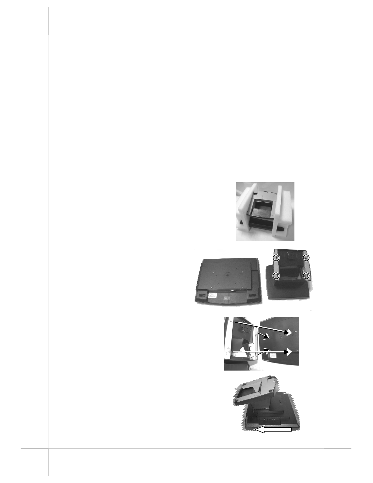
Since the monitor and stand are packaged separately,
please take out and hold the PE foams carefully and
DO NOT detach and drop it as show in the
following picture.
After take the PE foam out from the
carton, please remove the PE foam with
extra care and make sure place the
monitor and stand on a soft clean flat
surface such as table and as show in the
picture at the right side.
Please find the four holes in the top of stand.
Take the stand and align these four matching
holes to the four matching pegs which are in the
back on monitor.
After matching the stand and monitor, push the
stand to the arrowed direction as show in the right
picture. At this time, turn the monitor to the normal
position and plug the power then it can start to use.

Part 3
TM-8315
After open the carton, please take out the monitor carefully. Please place the
monitor’s bracket to the back of base stand and fasten the screws which circled
on the upper picture.
IV. PARTS IDENTIFICATION
A.
FRONT VIEW
TM/LM-8115
TM-8315
Display Screen
+ Touch Panel
Main Unit
Adjustable Base
Assembly
Option
SD-400Z
Logo + Power
Indicator
Display Screen
+ Touch Panel
Main Unit
Adjustable Base
Assembly
Option SD-400Z
Logo + Power
Indicator
Part 4
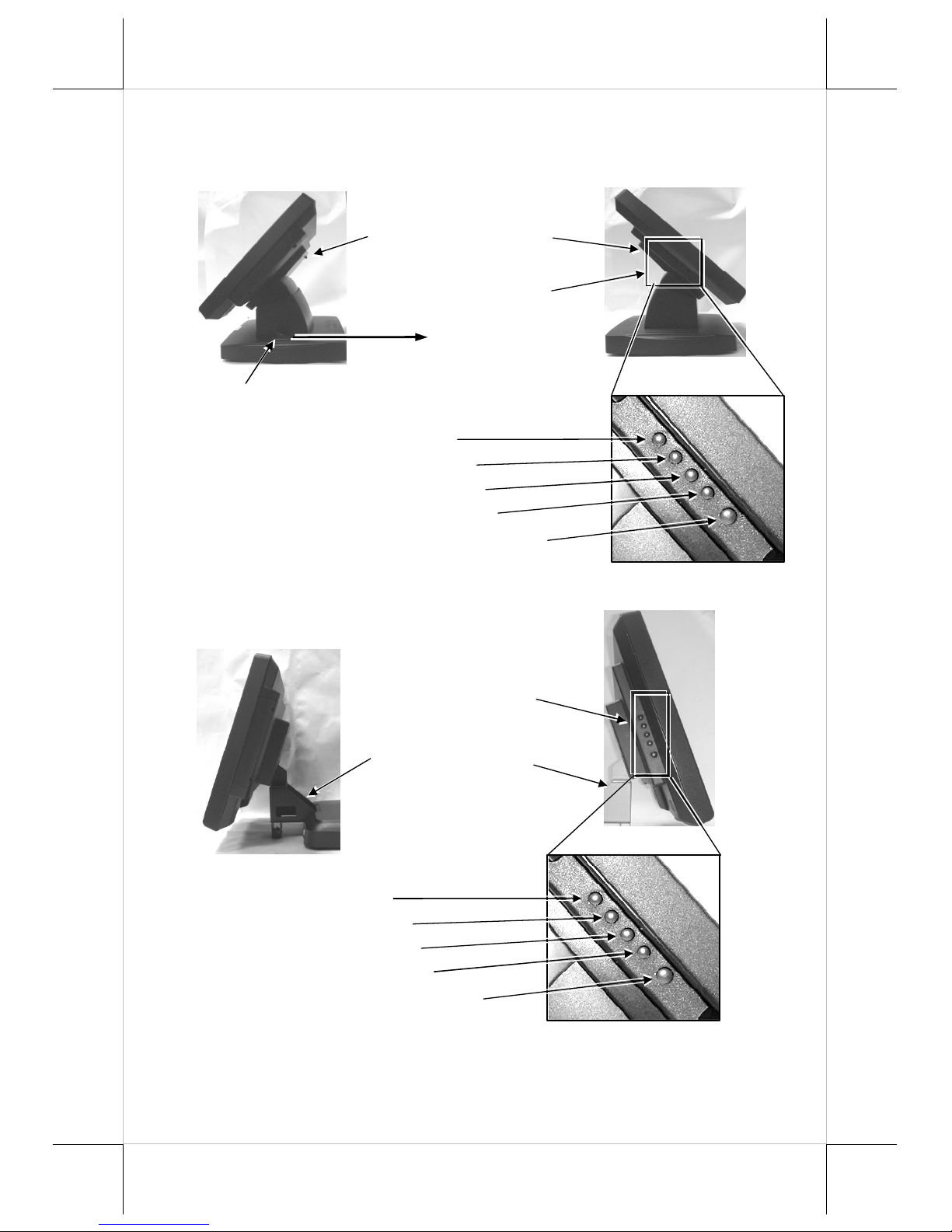
B.
SIDE VIEWS
TM/LM-8115
TM-8315
Lock/release lever
Push in this direction
to adjust the tilt angle
of the display panel
Control button area
Lock/release button to
detach the main unit
NXT button
“+” button
OSD button
“-“ button
Power switch
Control button area
Bracket to fix on the
base stand
NXT button
“+” button
OSD button
“-“ button
Power switch
Part 5
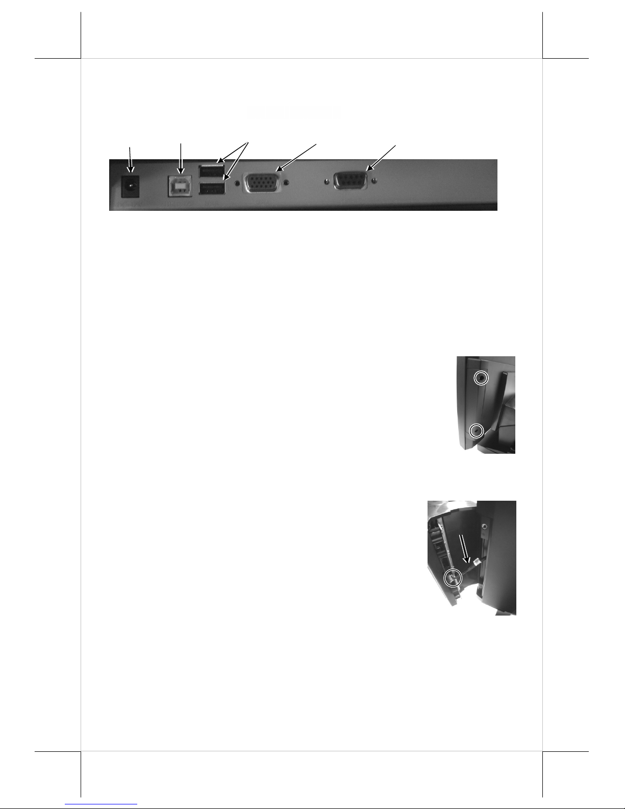
V. INPUT / OUTPUT PORTS
VI. AVAILABLE OPTION ITEMS
1. Side mount upgrade kit SD-400Z or KP-300
2. Wall mount kit (WB-6000V-B)
VII. HARDWARE INSTALLATION
A. Option Side Mount Upgrade Kit
When a side-mount upgrade kit option such as SD-400Z is
ordered with the LM-8115 / TM-8115 / TM-8315 monitor, this
option is already installed in the delivery. No matter the kit
itself contains MSR only, finger print sensor only or both
options, the connection to the LM-8115 / TM-8115 / TM-8315
monitor is through an internal cable in right side cover of the
LCD/touch unit. Remove the 2 circled screws in the right
picture to remove the cover for side mount upgrade kit as viewed from back of
the panel.
Take out the cable inside this cover as arrowed in the right
picture here and connect it to connector inside the side
mount upgrade kit as circled in the same picture. Gently
arrange the excessive length of this cable back in the hole
and screw-fit it back to the position originally occupied by
the cover. Please reserve the cover if there is chance to
have the side mount kit removed in the future.
B. Cable Connections For TM/LM-8115
In order to settle the touch monitor properly in a point of sale system, all the
cable connections have to be routed through its base. Therefore, please observe
the procedures from A to C below to separate the main unit from the base
stand assembly after all cables in connection area disconnected.
COM
(option RS232)
VGA
input
USB (B)
(to Host)
12 V DC
input
USB (A)
(to Devices)
 Loading...