

Page 1

Package Contents
RT-5015 15” fanless touch terminal or
RT-5016 15.6” fanless touch terminal or
RT-5115 15” fanless touch terminal or
RT-5116 15.6” fanless touch terminal (x 1)
Power adapter (x 1)
Power cord (x 1)
User manual (x 1)
16940900010 Ver. A0
http://www.posiflex.com
RT-5015/5016/5115/5116
Fanless Touch POS Terminal
User Manual
1
Page 2

Views of RT-5015/5016/5115/5116
Front View
15” RT-5015/5115 15.6” RT-5016/5116
Rear View
Bottom View
System Back Cover
Stand Cover
Cable Exit
RT-5015/5016/5115/5116
P-Cap Touch Panel
LED indicator
LED indicator
Base Stand
Camera (Optional)
Attachment Bay
Release Lever for System Back Cover
Screw for Fire-Resistant
System Back Cover
2
Page 3

Left-Side View
View of I/O Interface of RT-5015/5016/5115/5116
Positioning your POS for a Perfect Viewing Angle
Steady the base with one hand, and then tilt the screen
in the direction shown by the arrow in the figure.
Please do NOT press on the LCD panel while
setting up the tilt angle.
Power Button
Brightness Adjustment Button +
Brightness Adjustment Button -
USB 3.0 Ports
DB9 COM Port
CR Port
LAN Port
DC IN
Power
Connector
Mini DisplayPort
RJ50 COM Ports
USB 2.0 Ports
3
Page 4

Installing Power Adapter and Cables
The following provides instructions required to install your cables.
1. Lay the terminal with its rear facing
towards you and tilt the screen all the way
down.
2. Remove the system back cover.
2.1 If the system back cover is fire-resistant, first locate the screw as
indicated in the figure, and then remove it.
2.2 Hold down the release lever at the bottom of
the system back cover and then pulling the
cover outwards.
3. To remove the stand cover from the base, grab the top side of the
cover, (1) lift the stand cover up gently, (2) pull it at a 45 degree
angle, and then (3) slide it in the horizontal direction shown by the
arrow.
1 2 3
Screw for Fire-Resistant
System Back Cover
4
Page 5

4. Connect the connector of the power adapter
to the DC-IN power jack. If necessary,
properly insert other cables into the correct
port.
5. Neatly arrange the cables. Locate the cable holder inside the base as
shown in the figure. Push down the lever to release if from the hook,
pass the cable through cable holder, and then press down the lever
again to lock it onto the hook.
6. Make sure the cord can be held into place
and passed through the cable exit after
sliding back the stand cover.
7.
7.1 Place back the sytem back cover. Make sure
it is well locked into place with a click sound.
7.2 For the fire-resistant system back cover, please insert another
screw into the screw hole indicated in the figure, and secure it.
Cable holder
Screw for Fire-Resistant
System Back Cover
5
Page 6
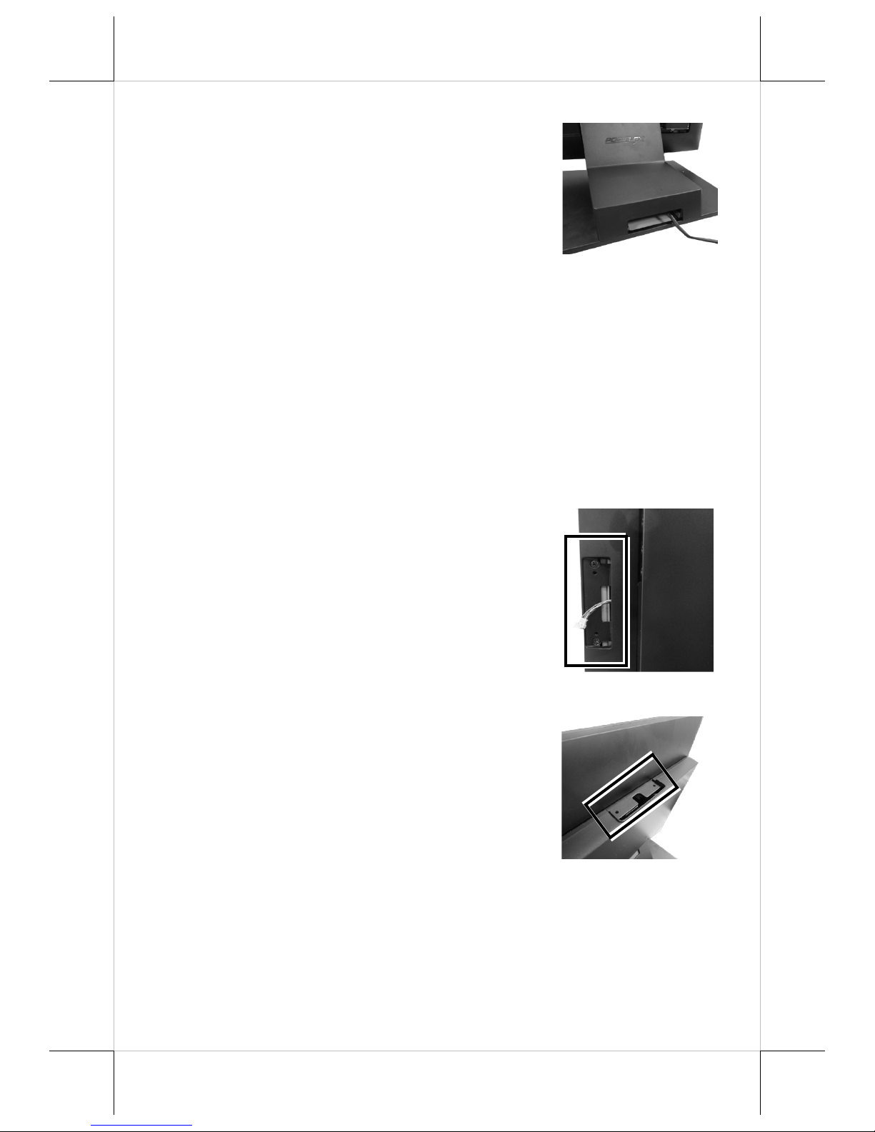
8. Make sure the cable could be pulled out of
the cable exit from the bottom of the base.
Installing Optional Upgrade Kits and Peripherals
RT-5015/5016/5115/5116 is an expandable model which allows you to
upgrade its own capacity by additionally installing multiple peripheral devices,
such as magnetic stripe reader (MSR), fingerprint or iButton sensors, and 2
nd
rear-mount POS monitor, according to your preference. The following will
give you brief instructions on how to expand on your current POS system with
these optional upgrade kits. Before proceeding with the installation of
peripherals, please make sure the POS system is completely shut down to
prevent damage.
Installing Side Mount Upgrade Kits
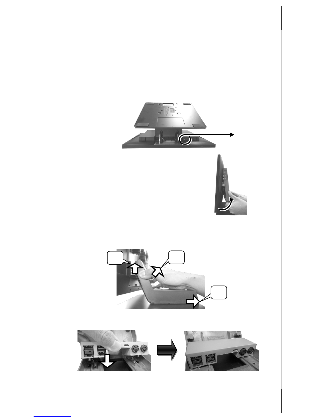
Located at left side on the back of your system
unit, side mount compartment is mainly used for
installation of side-mounted equipment, such as
magnetic stripe reader. For detailed installation
instructions, please refer to the user manual
specific to the device which you intend to
mount onto the terminal.
Installing Rear-Mount POS Monitor
RT-series POS terminal also allows you to
additionally install rear-mount POS monitor to
expand its functionality. Regarding the stepby-step instructions which aim to help you
mount it onto your POS system, Please refer
to the user manual specific to the device you
intend to install.
6
Page 7
Installing PoweredUSB or USB Hub
Please go through the below steps to complete the installation of
PoweredUSB or USB hub.
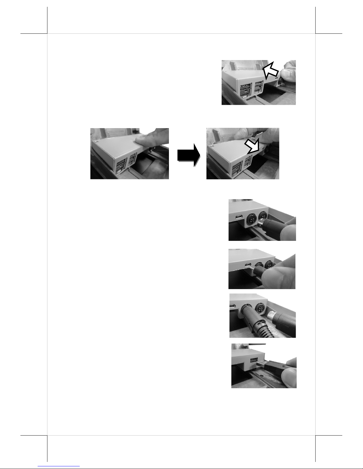
1. After tilting the screen all the way down, remove the system back
cover.
1.1 If the system back cover is fire-resistant, first locate the
screw as indicated in the figure, and then remove it.
1.2 Hold down the release lever at the
bottom of the system back cover and
then pulling the cover outwards
2. To remove the stand cover from the base, grab the top side of the
cover, (1) lift the stand cover up gently, (2) pull it at a 45 degree
angle, and then (3) slide it in the horizontal direction shown by the
arrow.
3. Align the two screw bolts at the bottom of PoweredUSB or USB hub
with rail slots in the base.
3
2
1
Screw for Fire-Resistant
System Back Cover
7
Page 8
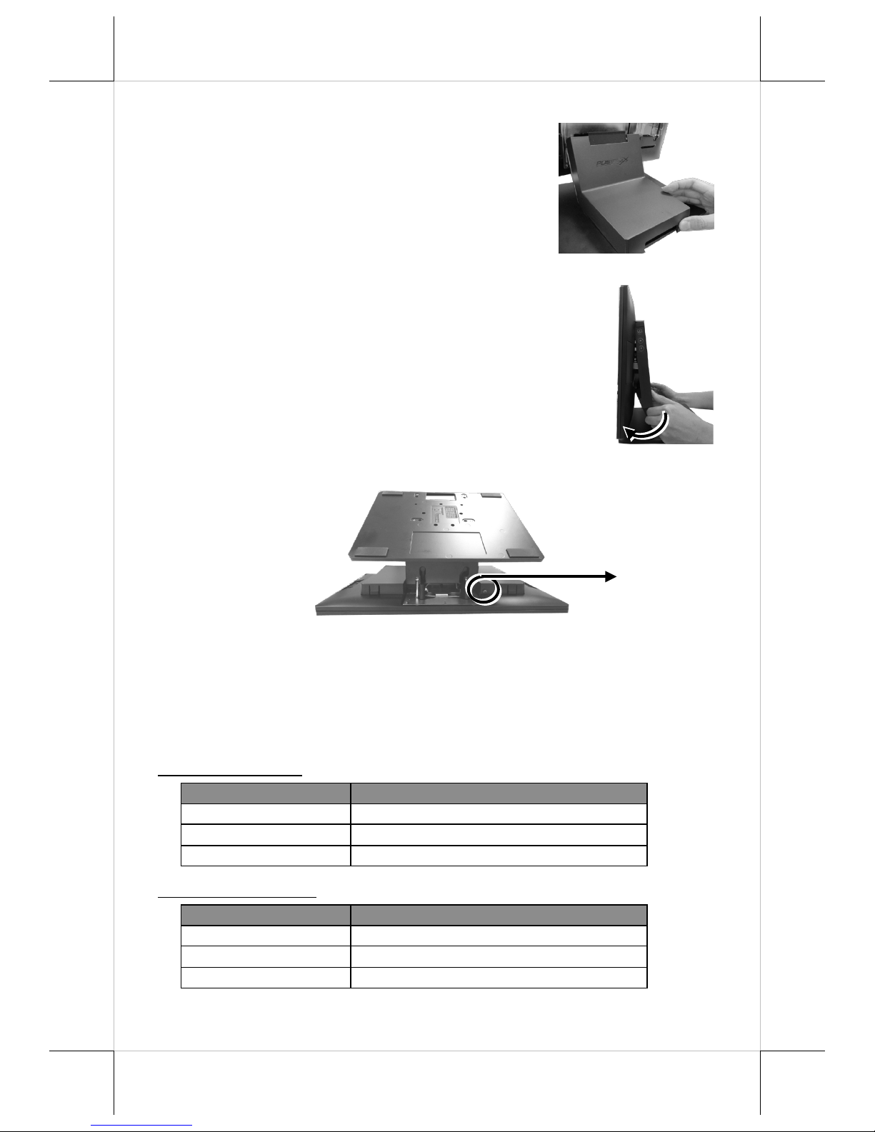
4.
Push PoweredUSB or USB hub in the
direction shown by the arrow to lock it
into place.
To remove the PoweredUSB or USB hub from the rail slots, press
down the hubs first and then push it outwards.
5. Install power adaptor extension cable, USB cable, and power adaptor
for PoweredUSB hub.
5.1 Insert one end of the provided power
adaptor extension cable to DC Input port
of PoweredUSB hub and another end to
DC-in power jack of the terminal.
5.2 Insert mini-USB connector of the USB
cable to PoweredUSB hub and another
end to USB3.0 port of the terminal.
5.3 Connect the connector of the power
adapter to DC Output port of
PoweredUSB hub, and the other end to the
electrical outlet.
6. To Install USB cable for USB hub, Plug
Type-A connector of USB cable to USB
Port of USB hub and the other end of USB
cable to USB3.0 port of the POS terminal.
8
Page 9
7. Neatly arrange your cable and then slide
back the stand cover.
8. .
8.1 Place back the sytem back cover. Make sure it
is well locked into place with a click sound
8.2 For the fire-resistant system back cover, please insert another
screw into the screw hole indicated in the figure, and secure it.
Status LED Indicator
LED status indicator, which is located at the bottom edge of the LCD panel, is
mainly responsible for notifying users of the current system status by emitting
various LED signals. In the chart provided below, it describes all the possible
LED status as a quick reference.
15” RT-5015/5115
LED Status
Description
Off
System power OFF
Green
System standby
Blue
System power ON
15.6” RT-5016/5116
LED Status
Description
Off
System power OFF
Orange
System standby
Blue
System power ON
Screw for Fire-Resistant
System Back Cover
9
Page 10
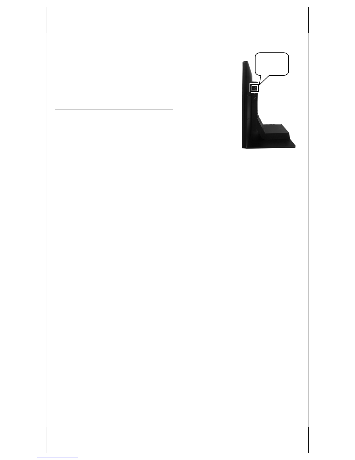
Powering ON/OFF RT-5015/5016/5115/5116
Power ON RT-5015/5016/5115/5116
Press down the power button to power on the POS.
Power OFF RT-5015/5016/5115/5116
In most cases, press the power button of the POS to
power the system off. If the terminal fails to turn off
the machine for unknown reasons, please be advised
to hold the power button more than 10 seconds to
force a shutdown of the system.
Installing an Operating System
You are highly advised not to install an operating system on RT5015/5016/5115/5116 without professional instructions. Improper installation
could lead to system malfunction or failure. Please contact with your dealers
about the issues of operating system installation.
Performing System Recovery
For RT-5015/5016/5115/5116 model with preloaded operating systems,
Recovery DVD which includes useful utilities will be provided in the package
to assist you in efficiently restoring or repairing your damaged system.
However, you are not encouraged to recover your system without the help of
system integrators. Please be advised to contact your service center for further
assistance with system recovery.
Operation Environment
To prevent RT-5015/5016/5115/5116 from overheating, it is suggested to
position your terminal in a well-ventilated working environment. In doing so,
please be advised to keep the POS terminal at least 25mm away from other
devices to ensure the machine is properly cooled down and functioning
normally.
Power
Button
10
Page 11
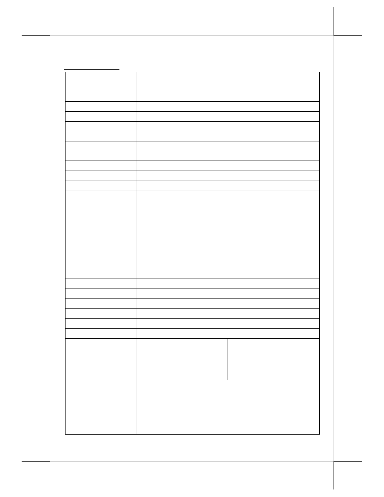
Specifications
RT-5015/5016
RT-5015
RT-5016
CPU
Intel Skylake-U CPU:
Core i3-6100U
System Memory
DDR4 SO-DIMM x 2
Storage Device
SATA Storage x 2
Power Supply
12V / 80W, can be upgraded to 150W while
adopting PoweredUSB module
LCD Panel
15"TFT LCD with
LED backlight
15.6" TFT LCD with
LED backlight
LCD Resolution
1024 x 768
1920 x 1080
Touch Sensor
P-CAP touch
Serial Port
3 ports, DB9 x 1+ RJ-50 x 2
USB Port
4 ports, USB3.0 x 2+ USB2.0 x 2
Additional USB port replicator ( USB2.0 x 4,
installed in base stand)
LAN Port
10/100/1000 Mb x 1
Display Port
eDP connector (internal header, support 15"
and 15.6" LCD panel)
VGA + USB + 12V (internal header,
supporting 2nd monitor 9.7"/10.1")
1 x Mini DP port (on I/O plate)
CR Port
1 port, controlling 2 CR
Audio Port
Internal 2W speaker x 1
Extension Slot
M.2 slot x 1
vPro
N/A
TPM
N/A
RAID
N/A
Dimension
(W x V x D in mm)
Main Unit:368 x 292 x
46.6
with base stand
:368 x
325 x 207
Main Unit:402 x 251 x
41.2
with base stand
:402 x
297 x 207
Environmental
Requirements
Operating:
0°C 〜 40°C, 20%RH - 90%RH (with HDD)
0°C 〜 50°C, 20%RH - 90%RH (with SSD)
Storage:
-20°C 〜 70°C, 10%RH - 90%RH
11
Page 12
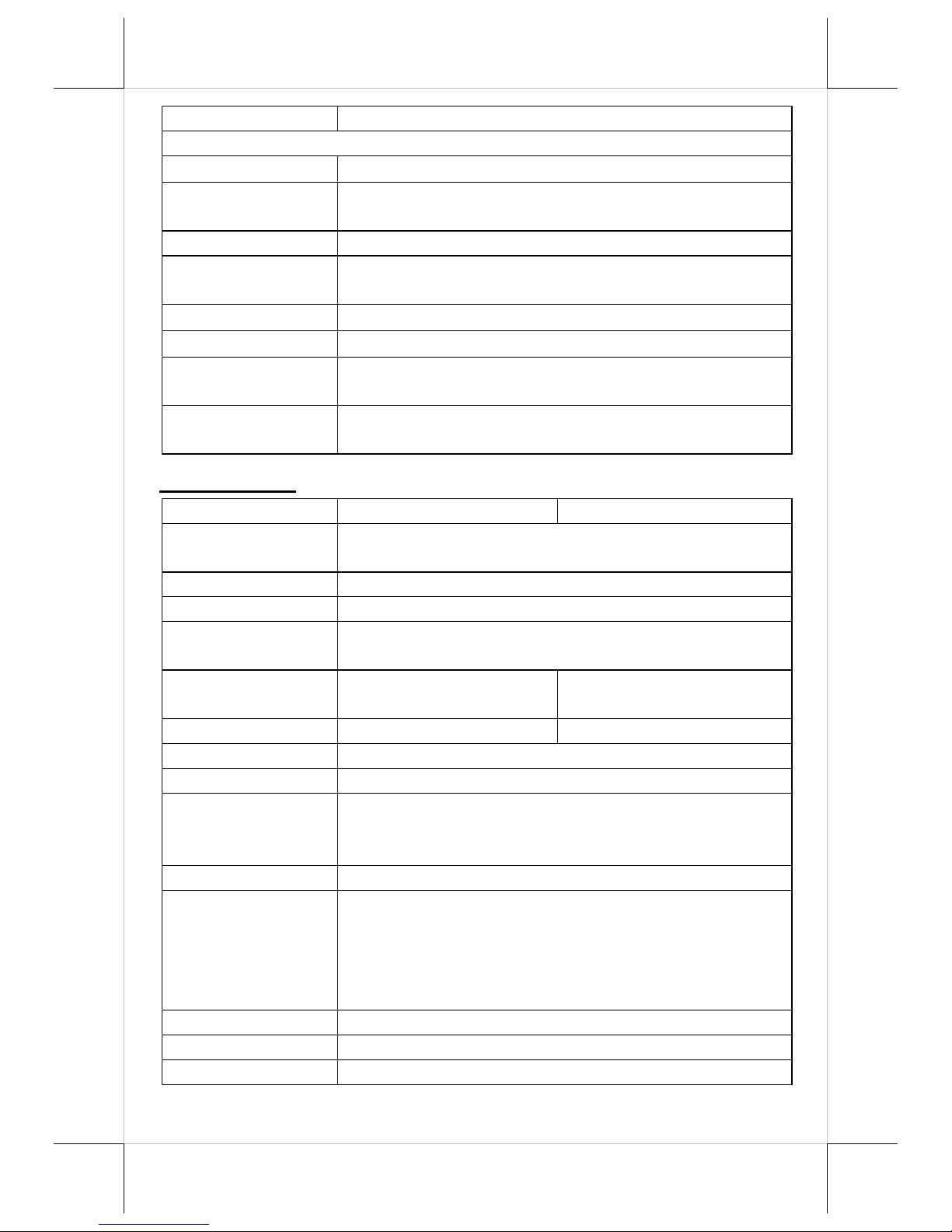
Regulation Rules
FCC/CE
Attachment
RA-101
Slim MSR attachment for RT series
RA-103
iButton (or RFID) with one USB port attachment
for RT series
RA-104
2D scanner attachment for RT series
RA-301
3-in-1 MSR + Fingerprint Sensor + 2D scanner
attachment for RT series
LM/TM-4010
9.7" 2nd display for RT series terminal
LM/TM-4011
10.1" 2nd display for RT series terminal
PU-460
PoweredUSB module to support 12Vand 24V
Powered USB ports
RT-560
USB port replicator ( USB2.0 x 4, installed in base
stand)
RT-5115/5116
RT-5115
RT-5116
CPU
Intel Skylake-U CPU:
Core i5-6300U
System Memory
DDR4 SO-DIMM x 2, max. 16GB
Storage Device
SATA Storage x 2
Power Supply
12V / 80W, can be upgraded to 150W while
adopting PoweredUSB module
LCD Panel
15"TFT LCD with
LED backlight
15.6" TFT LCD with
LED backlight
LCD Resolution
1024 x 768
1920 x 1080
Touch Sensor
P-CAP touch
Serial Port
3 ports, DB9 x 1+ RJ-50 x 2
USB Port
4 ports, USB3.0 x 2+ USB2.0 x 2
Additional USB port replicator ( USB2.0 x 4,
installed in base stand)
LAN Port
10/100/1000 Mb x 1
Display Port
eDP connector (internal header, support 15"
and 15.6" LCD panel)
VGA + USB + 12V (internal header,
supporting 2nd monitor 9.7"/10.1")
1 x Mini DP port (on I/O plate)
CR Port
1 port, controlling 2 CR
Audio Port
Internal 2W speaker x 1
Extension Slot
M.2 slot x 1
12
Page 13
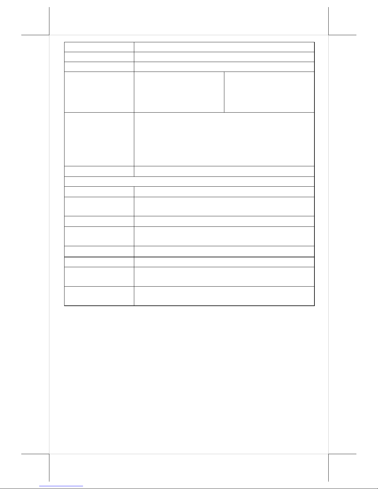
vPro
Yes
TPM
Yes
RAID
Yes
Dimension
(W x V x D in mm)
Main Unit:368 x 292 x
46.6
with base stand
:368 x
325 x 207
Main Unit:402 x 251 x
41.2
with base stand
:402 x
297 x 207
Environmental
Requirements
Operating:
0°C 〜 40°C, 20%RH - 90%RH (with HDD)
0°C 〜 50°C, 20%RH - 90%RH (with SSD)
Storage:
-20°C 〜 70°C, 10%RH - 90%RH
Regulation Rules
FCC/CE
Attachment
RA-101
Slim MSR attachment for RT series
RA-103
iButton (or RFID) with one USB port attachment
for RT series
RA-104
2D scanner attachment for RT series
RA-301
3-in-1 MSR + Fingerprint Sensor + 2D scanner
attachment for RT series
LM/TM-4010
9.7" 2nd display for RT series terminal
LM/TM-4011
10.1" 2nd display for RT series terminal
PU-460
PoweredUSB module to support 12Vand 24V
Powered USB ports
RT-560
USB port replicator ( USB2.0 x 4, installed in base
stand)
※
The product information and specifications are subject to change without
prior notice. To get the detailed information on the RT-5015/5016/5115/5116,
please check this model from Posiflex Global Website
13
Page 14

<MEMO>
14
Page 15

<MEMO>
15
Page 16

<MEMO>
16
 Loading...