

PG-200/2D
2D Image Scanner
User Manual
PG-200/2D
Package Contents
Pistol grip with 2D image scanner (x1)
Stylus (x 1)
Battery pack for pistol grip (x 1)
PG-200/2D user manual (x 1)
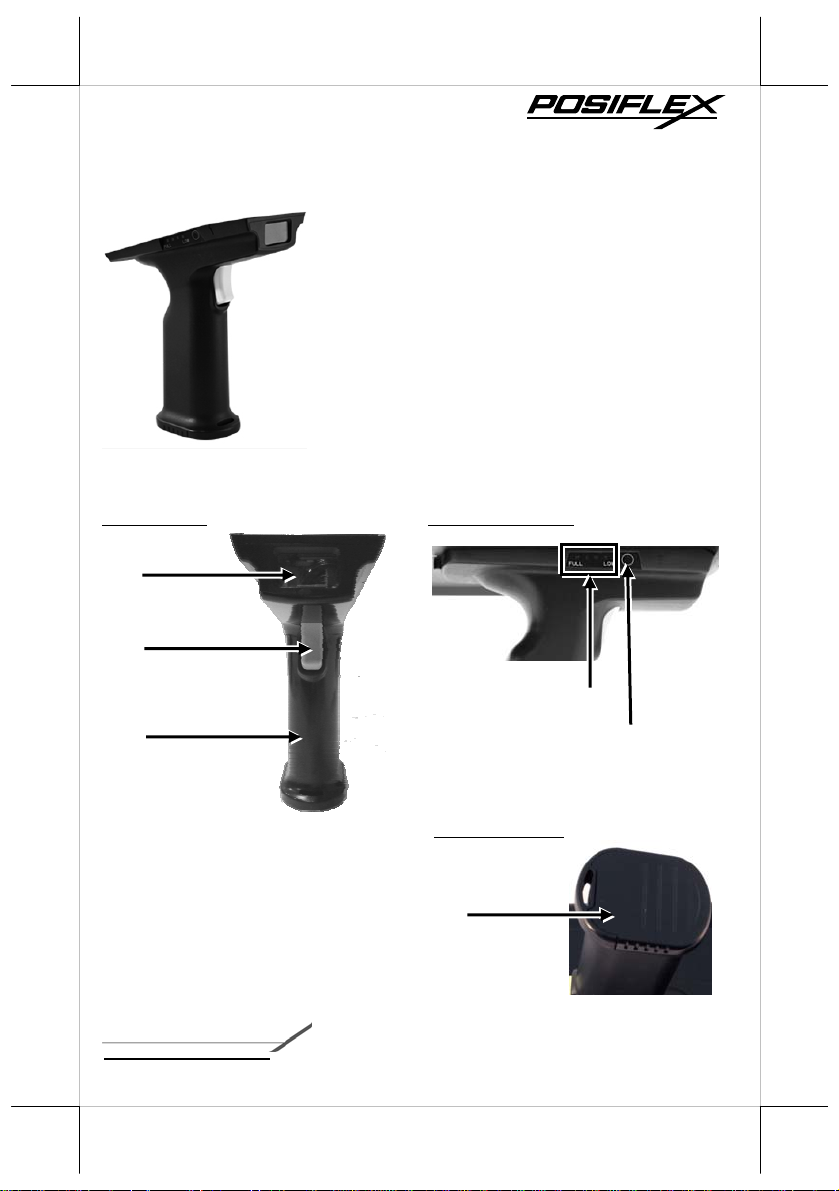
Views of the PG-200/2D
Front view Left Side View
2D Image Scanner
Trigger Button
Battery Capacity Indicator
Pistol Grip
Battery Cap
acity Checking Button
Bottom View
Battery Pack Cover
12530903010 Ver. Original
http://www.posiflex.com
1
Load a Battery Pack and a stylus into the Pistol Grip
A user who purchases the PG-200/2D model has a battery pack for pistol grip.
Besides, the user also has a stylus that is packed in the package box. To install
the battery pack and stylus, refer to the MT-4008W user manual.
Caution: After loading the battery into the pistol grip, remember to
charge the battery pack first with a charger or a power adaptor
connected between the tablet and an electrical outlet. For the
detailed description of battery charging, refer to the section
titled “Charging the Battery” as described in the MT-4008W.
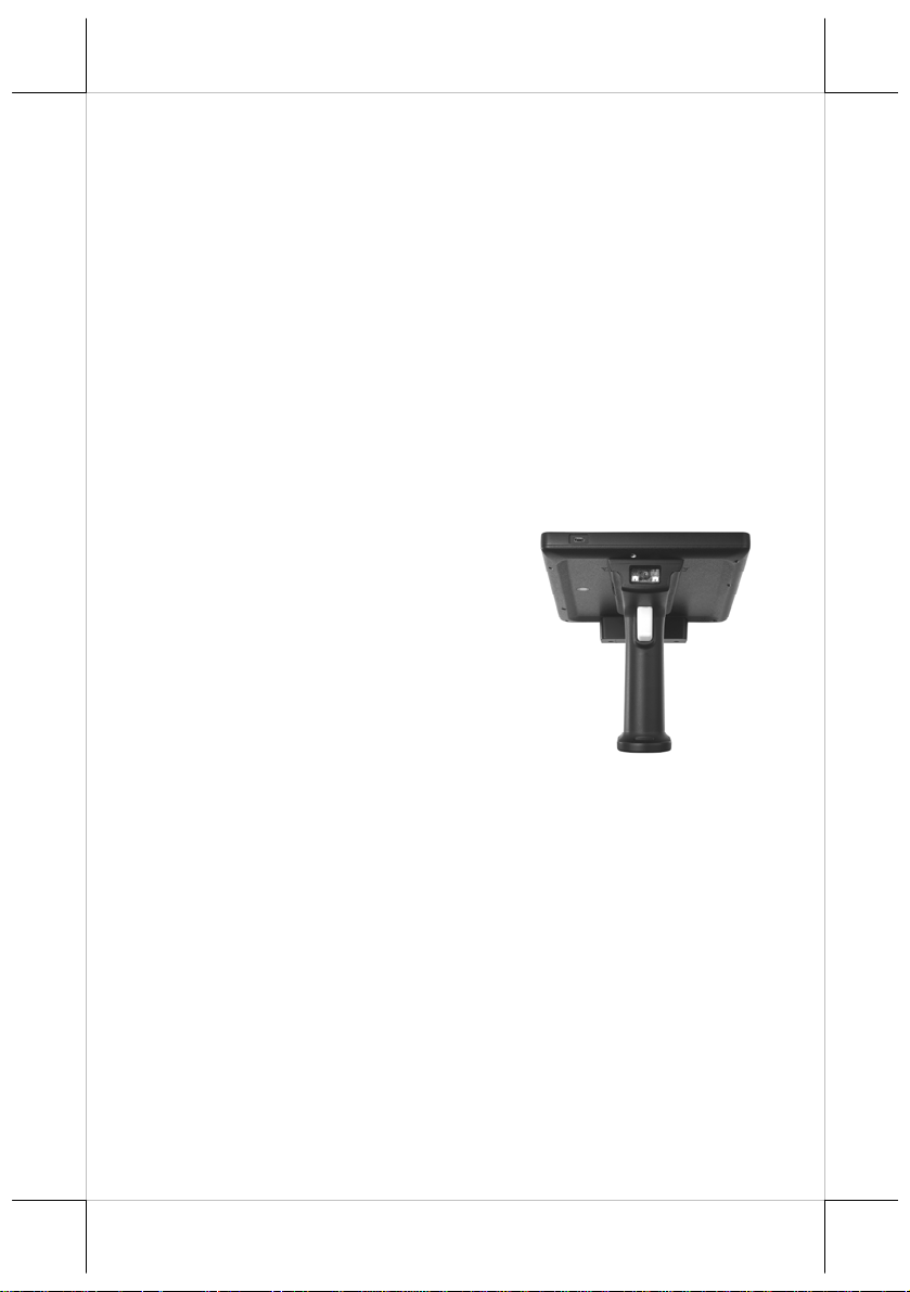
Connecting the Pistol Grip onto the Tablet
The pistol grip is provided with a 2D scan engine. Posiflex pi st ol gri p
equipped with the 2D scan engine is just a gun grip for users to easily operate
the scanner. To install the pistol grip onto the tablet, refer to the MT-4008W
user manual.
Operating the 2D Image Scanner
This scanner works to scan 2D barcodes. The
scanner can work in USB HID or USB
Virtual COM mode. By default, the scanner
works in USB HID mode.
The factory default settings are shown with < > and bold in the following
sections. You can make your own settings by scan a series of selected barcode
patches in this man ual to af fect setup and program mi ng of your handheld 2D
Image Reader.
Scan a series of selected barcode patches in this m anual to af fect setup an d
programming of your handheld 2D Image Reader. Decoding options and
interface protocols can be tailored to a specific application.
Setup parameters are stored in the non-volatile memory of the scanner and are
retained even when power is off. Setup parameters change only when you reset
them.
Y o u may need to hide adja cent code pat ches wi th your han d when d o ing
programming scanning.
2
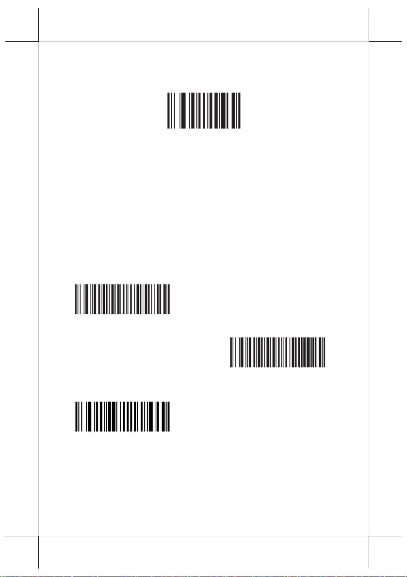
Set Default Parameter
Write to Custom Defaults - Scan this bar code to set the current decoder
settings as custom defaults.
Write to Custom Defaults
Trigger Modes
Level Mode - A trigger event activates decode processing, which continues
until the trigger event ends, a valid decode, or the decode session time-out is
reached. This scan mode is not available for scan module.
Presentation Mode - When the device detects an object in its field of view it
triggers and attempts to decode. The range of object detection does not vary
under normal lighting conditions. This applies to decode mode only. In this
mode the unit does not enter its sleep state.
Host Mode - A host command issues the t rig gering signal. The device
interprets a trigger pull as a level triggering option. This scan mode is not
available for scan module.
< Level Mode >
(Default for handheld scanners.)
< Presentation Mode >
(Default for desktop and fixed mount
scan modules)
Host Mode
3
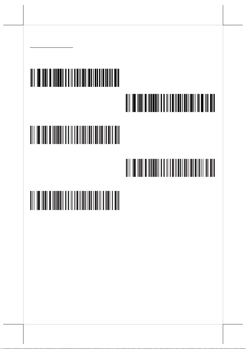
USB Host Parameters
USB Device Type
Select the desired USB device type.
Note: When changing USB Device Types, the decoder automatically resets.
The decoder issues the standard startup beep sequences.
< HID Keyboard Emulation >
USB virtual COM port emulat i on
(requiring driver)
Simple COM Port Emulation
(requiring driver)
Native API (SNAPI) without
Imaging Interface
Native API (SNAPI) with
4
Interface
Imaging
USB Polling Interval
This option speeds up the USB HID Keyboard Emulation Device. Scan a bar
code below to set the polling interval. The polling interval determines the rate
at which data can be sent between the decoder and the host computer. A lower
number indicates a faster data rate. The default value is 8 msec.
When the polling interval is changed the decoder re-initializes.
CAUTION: Ensure your host machine can handle the selected data rate.
Selecting a data rate that is too fast for your host machine may
result in lost data.
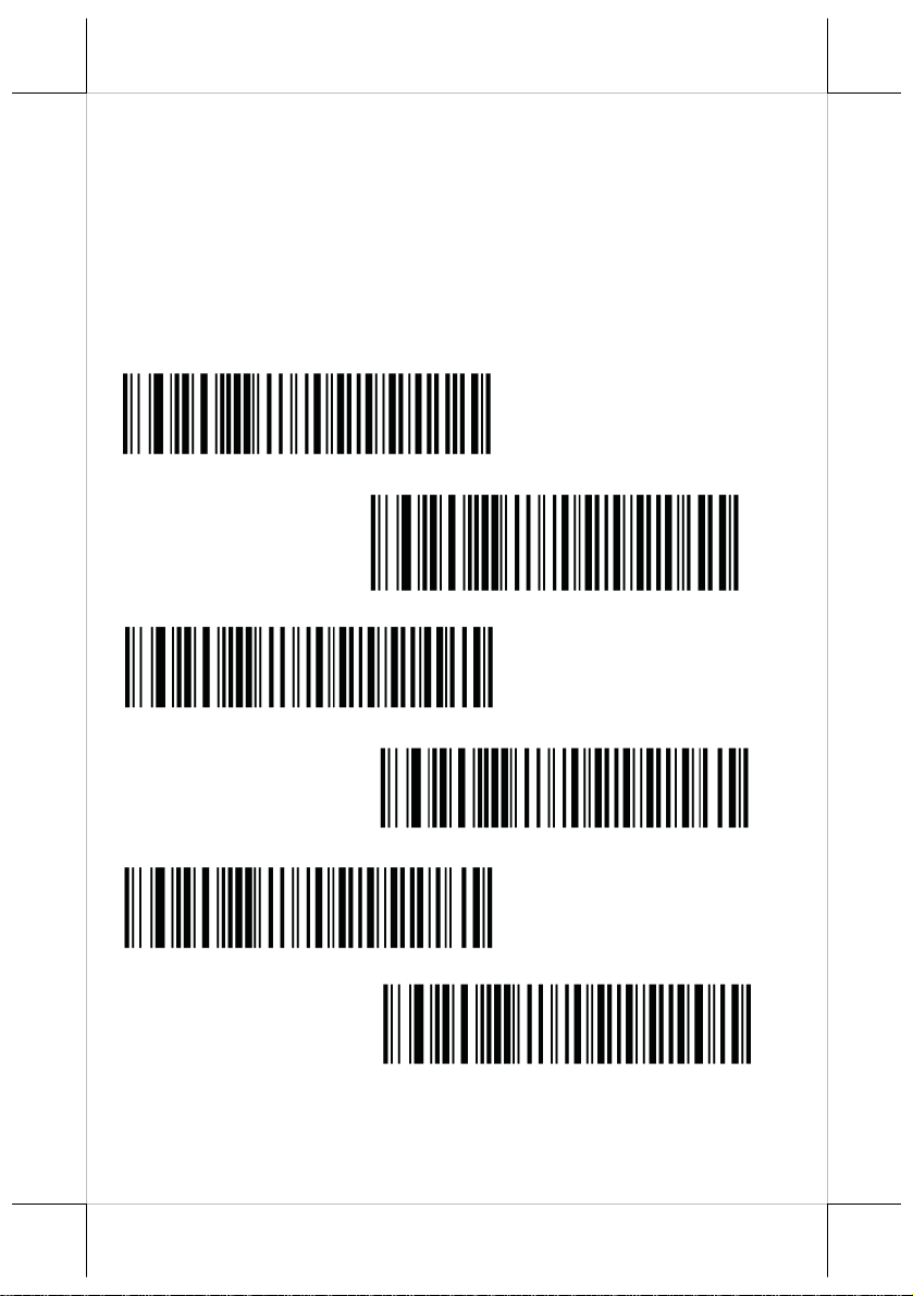
1 msec
2 msec
*3 msec
4 msec
5 msec
6 msec
5
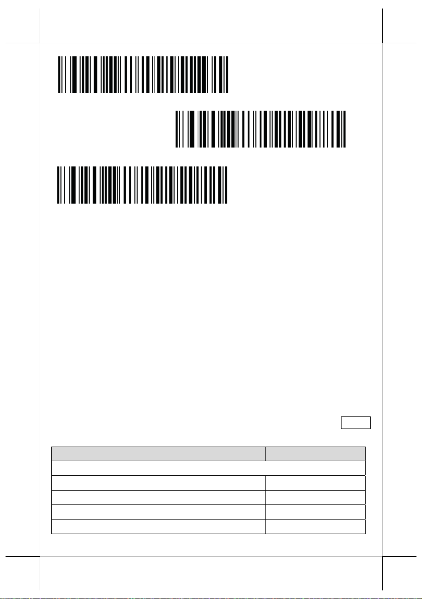
7 msec
8 msec
9 msec
Symbologies
The device is shipped with the settings shown in the Symbology Default Table
if the default values suit requirements; programming is not necessary.
There are two ways to change a parameter value:
Scan the appropriate bar codes in this guide. These new values replace
the standard default values in m emory.
For SSI and USB SNAPI hosts, send a “param eter send” co mm and from
the host system. Hexadecimal parameter numbers are shown in this section
below the parameter title, and options are shown in parenthesis beneath the
accompanying bar codes.
Note: Most computer monitors allow scanning the bar codes directly on the
screen. When scanning them on the screen, be sure to set the document
magnification to a level where the bar code can be seen clearly, and bars
and/or spaces are not merging.
To return all features to default values, scan the Set Default Parameter bar
code. Throughout the programming bar code menus, default values are framed.
Symbology Default Table
Parameter Default
UPC/EAN
UPC-A Enable
UPC-E Enable
UPC-E1 Disable
EAN-8/JAN 8 Enable
6

Parameter Default
EAN-13/JAN 13 Enable
Code 128
Code 128 Enable
UCC/EAN-128 Enable
ISBT 128 Enable
Code 39
Code 39 Enable
Trioptic Code 39 Disable
Convert Code 39 to Code 32 (Italian Pharmacy Code) Disable
Code 39 Full ASCII Conversion Disable
Code 93
Code 93 Disable
Code 11
Code 11 Disable
Interleaved 2 of 5 (ITF)
Interleaved 2 of 5 (ITF) Enable
Discrete 2 of 5 (DTF)
Discrete 2 of 5 Disable
Codabar
Codabar Disable
MSI
MSI Disable
RSS (Reduced Space Symbology)
RSS 14 Enable
RSS Limited Enable
RSS Expanded Enable
Convert RSS to UPC/EAN Disable
2D Symbologies
PDF417 Enable
MicroPDF417 Disable
Code 128 Emulation Disable
Data Matrix Enable
7

Parameter Default
Maxicode Enable
QR Code Enable
Symbology-Specific Security Levels
Redundancy Level 1
Security Level 1
Inter character Gap Size Normal
Report Version
Macro PDF
Macro PDF Transmit/Decode Mode Symbols Pass through Mode
Transmit Macro PDF Control Header Disable
Escape Characters None
Flush Macro PDF Buffer
Abort Macro PDF Entry
UPC/EAN
Enable/Disable UPC-A
< Enable UPC-A >
Enable/Disable UPC-E
< Enable UPC-E >
Disable UPC-A
Disable UPC-E
8

Enable/Disable UPC-E1
UPC-E1 is disabled by default. To enable or disable UPC-E1, scan the
appropriate bar code below.
Note: UPC-E1 is not a UCC (Uniform Code Council) approved symbology .
Enable UPC-E1
Enable/Disable EAN-8/JAN-8
< Disable
UPC-E1
>
< Enable EAN-8/JAN-8 >
Disable EAN-8/JAN-8
Enable/Disable EAN-13/JAN-13
< Enable EAN-13/JAN-13 >
Disable EAN-13/JAN-13
Convert UPC-E to UPC-A
Enable this to convert UPC-E (zero suppressed) decoded data to UPC-A
format before transmission. After conversion, the data follows UPC- A fo r m at
and is affected by UPC-A programming selections (e.g., Preamble, Check
Digit). When being di sabled, UPC-E decode d dat a is transmitted as UPC-E
data,
without conversion.
Convert UPC-E to UPC-A (Enable)
9

< Do Not
Convert UPC-E1 to UPC-A
Enable this to convert UPC-E1 decoded data to UPC-A format before
transmission. After conversion, the data follows UPC-A format and is affected
by UPC-A programming selections (e.g., Preamble, Check Digit).
When disabled, UPC-E1 decoded data is transmitted as UPC-E1 data, without
conversion.
Convert UPC-E to UPC-A
(Disable)
>
Convert UPC-E1 to UPC-A (Enable)
Code 128
Enable/Disable Code 128
< Do Not
UPC-A
Convert UPC-E1 to
> (Disable)
< Enable Code 128 >
Enable/Disable UCC/EAN-128
< Enable UCC/EAN-128 >
10
Disable Code 128
Disable UCC/EAN-128

Code 39
Enable/Disable Code 39
< Enable Code 39 >
Disable Code 39
Convert Code 39 to Code 32
Code 32 is a variant of Code 39 used by the Italian pharmaceutical industry.
Scan the appropriate bar code below to enable or disable converting Code 39 to
Code 32.
Note: Code 39 must be enabled for this parameter to function.
Enable Convert Code 39 to Code 32
< Disable
Code 39 Full ASCII Conversion
Code 39 Full ASCII is a variant of Code 39 which pairs characters to encode
the full ASCII character set. To enable or disable Code 39 Full ASCII, scan the
appropriate bar code below.
Convert Code 39 to Code 32 >
Enable Code 39 Full ASCII
< Disable
Code 39 Full ASCII to Full ASCII Correlation is host-dependent, and is
therefore described in the ASCII Character Set Table for the appropriate
interface. See Appendix C, ASCII Character Set.
11
Code 39 Full ASCII
>

Code 93
Enable/Disable Code 93
Enable Code 93
< Disable Code 93 >
Code 11
Enable Code 11
< Disable Code 11 >
Interleaved 2 of 5 (ITF)
Enable/Disable Interleaved 2 of 5
To enable or disable Interleaved 2 of 5, scan the appropriate bar code below,
and select an Interleaved 2 of 5 length from the following pages.
< Enable
Interleaved 2 of 5
>
Disable Interleaved 2 of 5
Discrete 2 of 5 (DTF)
Enable/Disable Discrete 2 of 5
To enable or disable Discrete 2 of 5, scan the appropriate bar code below.
Enable Discrete 2 of 5
12

Codabar
Enable/Disable Codabar
Enable Codabar
MSI
Enable/Disable MSI
Enable MSI
GS1 DataBar
< Disable
Discrete 2 of 5
>
< Disable
Codabar
>
< Disable
MSI
>
<Enable GS1 DataBar>
GS1 DataBar Limited
Enable GS1 DataBar Limited
Disable GS1 DataBar
13

2D Symbologies
PDF417
Enable/Disable PDF417
<Disable GS1 DataBar Limited>
< Enable PDF417 >
MicroPDF417
Enable/Disable MicroPDF417
Enable MicroPDF417
Data Matrix
< Enable
Data Matrix
>
Disable PDF417
< Disable
MicroPDF417
>
Disable Data Matrix
Maxicode
< Enable Maxicode >
14

Disable Maxicode
QR Code
< Enable
QR Code
>
Disable QR Code
Miscellaneous Scanner Options
Miscellaneous Scanner Parameters
TRANSMIT CODE ID
A Code ID character identifies the code type of a scanned bar code. This is
useful when the decoder is decoding more than one code type. In addition to
any single character prefix already selected, the Code ID character is inserted
between the prefix and the decoded symbol.
Select no Code ID character, a Default Code ID character, or an AIM Code ID
character. For Code ID Characters, see Default Code Identifiers and AIM Code
Identifiers.
Default Code ID Character
< None >
AIM Code ID Character
15

Prefix/Suffix Values
A prefix and/or one or two suffixes can be appended to scan data for use in
data editing. To set a value for a prefix or suffix, scan a prefix or suffix bar
code below, then scan a four-digit number (i.e., four barcodes, Numeric Bar
Codes) that corresponds to that value. To correct an error or change a selection,
scan Cancel barcode.
Note: To use Prefix/Suffix values, first set the Scan Data Transmission Format.
For non-SSI hosts, when using host commands to set the prefix or suffix, set
the key category parameter to 1, then set the 3-digit decimal value.
Scan Prefix
Scan Suffix 1
Scan Suffix 2
Scan Data Transmission Format
To set values for the prefix and/or suffix, see Prefix/Suffix Values.
< Data As ls >
<DATA> <SUFFIX 1>
<DATA> <SUFFIX 2>
<DATA> <SUFFIX 1> <SUFFIX
2>
16

<PREFIX> <DATA >
<PREFIX> <DATA> <SUFFIX 1>
<PREFIX> <DATA> <SUFFIX 2>
<PREFIX> <DATA> <SUFFIX 1>
<SUFFIX 2>
Default Code Identifiers
Default Code Characters
Code Character Code Type
A UPC-A, UPC-E, UPC-E1, EAN-8, EAN-13
B Code 39, Code 32
C Codabar
D Code 128
E Code 93
F Interleaved 2 of 5
G Discrete 2 of 5, or Discrete 2 of 5 IATA
H Code 11
J MSI
K UCC/EAN-128
L Bookland EAN
17

Code Character Code Type
M Trioptic Code 39
N Coupon Code
R RSS Family
T UCC Composite, TLC 39
X PDF417, Macro PDF417, Micro PDF417
P00 Data Matrix
P01 QR Code
P02 Maxicode
P03 US Postnet
P04 US Planet
P05 Japan Postal
P06 UK Postal
P08 Dutch Postal
P09 Australian Postal
P09 UK Postal
AIM Code Identifiers
Each AIM Code Identifier contains the three-character string] cm where:
] = Flag Character (ASCII 93)
c = Code Character
m = Modifier Character
Code Character Code Type
A Code 39, Code 39 Full ASCII, Code 32
Aim Code Characters
18

C Code 128, Coupon (Code 128 portion)
d Data Matrix
E UPC/EAN, Coupon (UPC portion)
e RSS Family
F Codabar
G Code 93
H Code 11
I Interleaved 2 of 5
L PDF417, Macro PDF417, Micro PDF417
M MSI
Q QR Code
S Discrete 2 of 5, IATA 2 of 5
U Maxicode
X
Numeric Bar Codes
0
2
Bookland EAN, Trioptic Code 39, US Postnet, US
Planet, UK Postal, Japan Postal, Australian Postal,
Dutch Postal
1
19

3
4
6
8
Cancel
To correct an error or change a selection, scan the bar code below.
5
7
9
Cancel
20
 Loading...