

PG-200/1D
1D Barcode Scanner
User Manual
PG-200/1D
Package Contents
Pistol grip with 1D barcode scanner
(x1)
Stylus (x 1)
Battery pack for pistol grip (x 1)
PG-200/1D user manual (x 1)
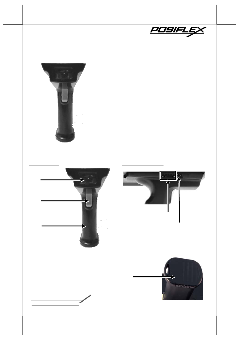
Views of the PG-200/1D
Front view Left Side View
1D Barcode Scanner
Trigger Button
Battery Capacity Indicator
Pistol Grip
Battery Cap
acity Checking Button
Bottom View
Battery Pack Cover
12530902010 Ver. Original
http://www.posiflex.com
1
Load a Battery Pack and a stylus into the Pistol Grip
A user who purchases the PG-200/1D model has a battery pack
for pistol grip. Besides, the user also has a stylus that is packed in
the package box. To install the battery pack and stylus, refer to
the MT-4008W user manual.
Caution: After loading the battery into the pistol grip,
remember to charge the battery pack first with a charger or a
power adaptor connected between the tablet and an electrical
outlet. For the detailed description of battery charging, refer
to the section titled “Charging the Battery” as described in
the MT-4008W.
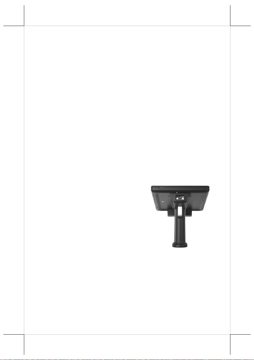
Connecting the Pistol Grip onto the Tablet
The pistol grip is provided with a 1D scan engine. Posiflex pistol
grip equipped with the 1D scan engine is just a gun grip for users
to easily operate the scanner. To install the pistol grip onto the
tablet, refer to the MT-4008W user manual.
Operating the 1D Barcode Scanner
This scanner works to scan 1D
barcodes. The scanner can work in
USB HID or USB Virtual COM
mode. By default, the scanner works
in USB HID mode.
2
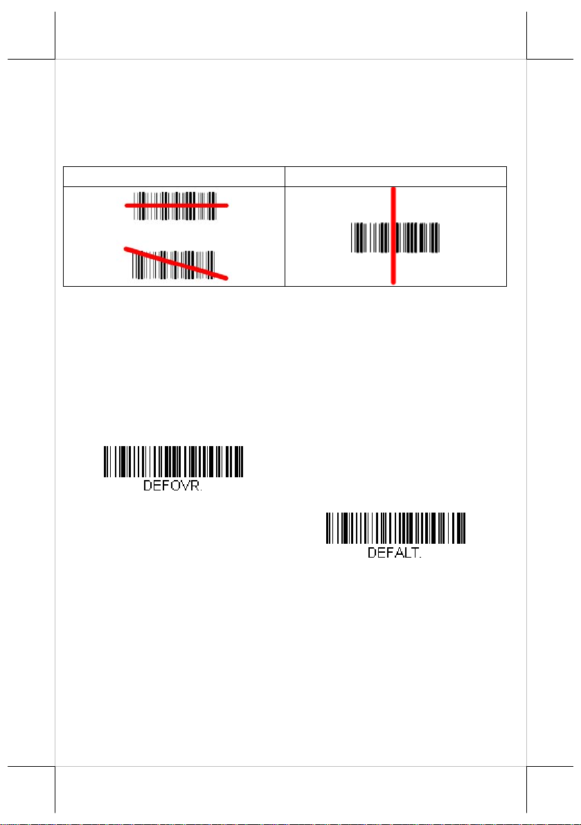
The engine projects a bright red scan beam that corresponds to the
engine’s
centered horizontally over the
scanning field of view. The scan beam should be
bar code and must highlight all the
vertical bars of the bar code. It will not read if the scan beam is in
any other direction.
Good Read No Read
Resetting the Factory Defaults
Caution! This selection erases all your settings and resets the engine to the
original factory defaults. It also disables all plugins.
If you aren’t sure what programming options are in your engine,
or you’ve
factory default setbar code, then scan Activate Defaults. This resets the engine to
the factory default settings.
changed some options and want to restore the engine to
tings, first scan the Remove Custom Defaults
Remove Custom Defaults
Activate Defaults
3
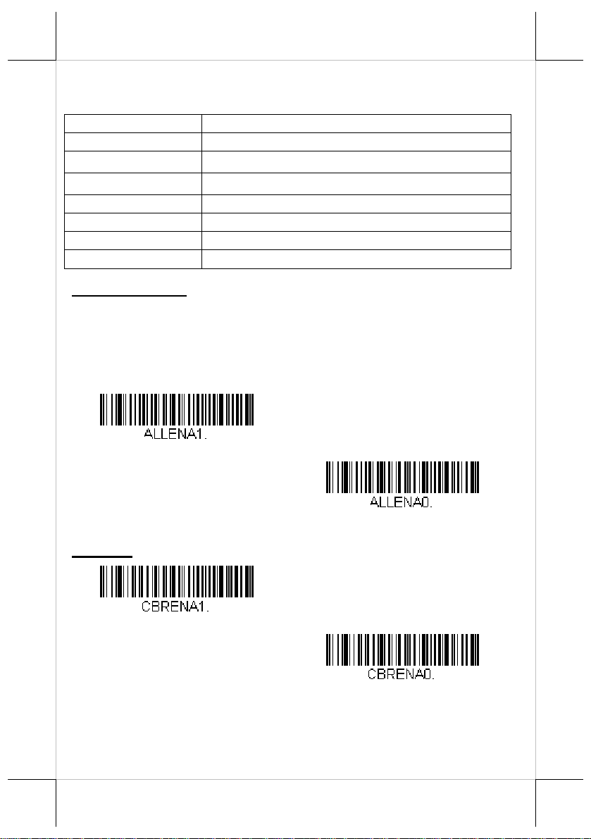
Symbologies
This programming section contains the following menu selections.
All Symbologies
Code 39 Code 93
Interleaved 2 of 5
UPC-A
Code 128
Telepen Code 11
EAN/JAN-13
UPC-E0
All Symbologies
If you want to decode all the symbologies allowable for your
engine, scan the All Symbologies On code. On the other hand, if
you want to decode only a particular symbology, scan All
Symbologies Off followed by the On symbol for
symbology.
Codabar
Matrix 2 of 5
UPC-A/EAN-13 with Extended Coupon Code
EAN/JAN-8
MSI
that particular
All Symbologies On
Codabar
All Symbologies Off
* On
Off
4
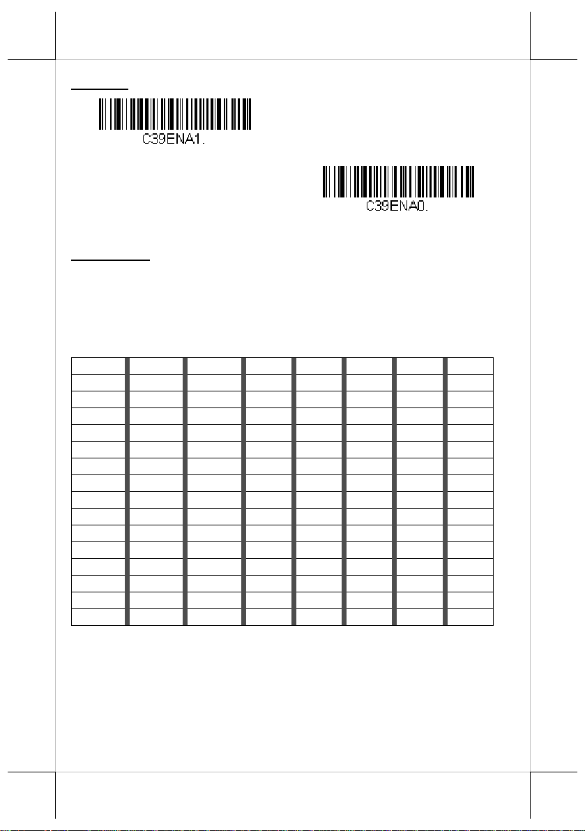
Code 39
* On
Off
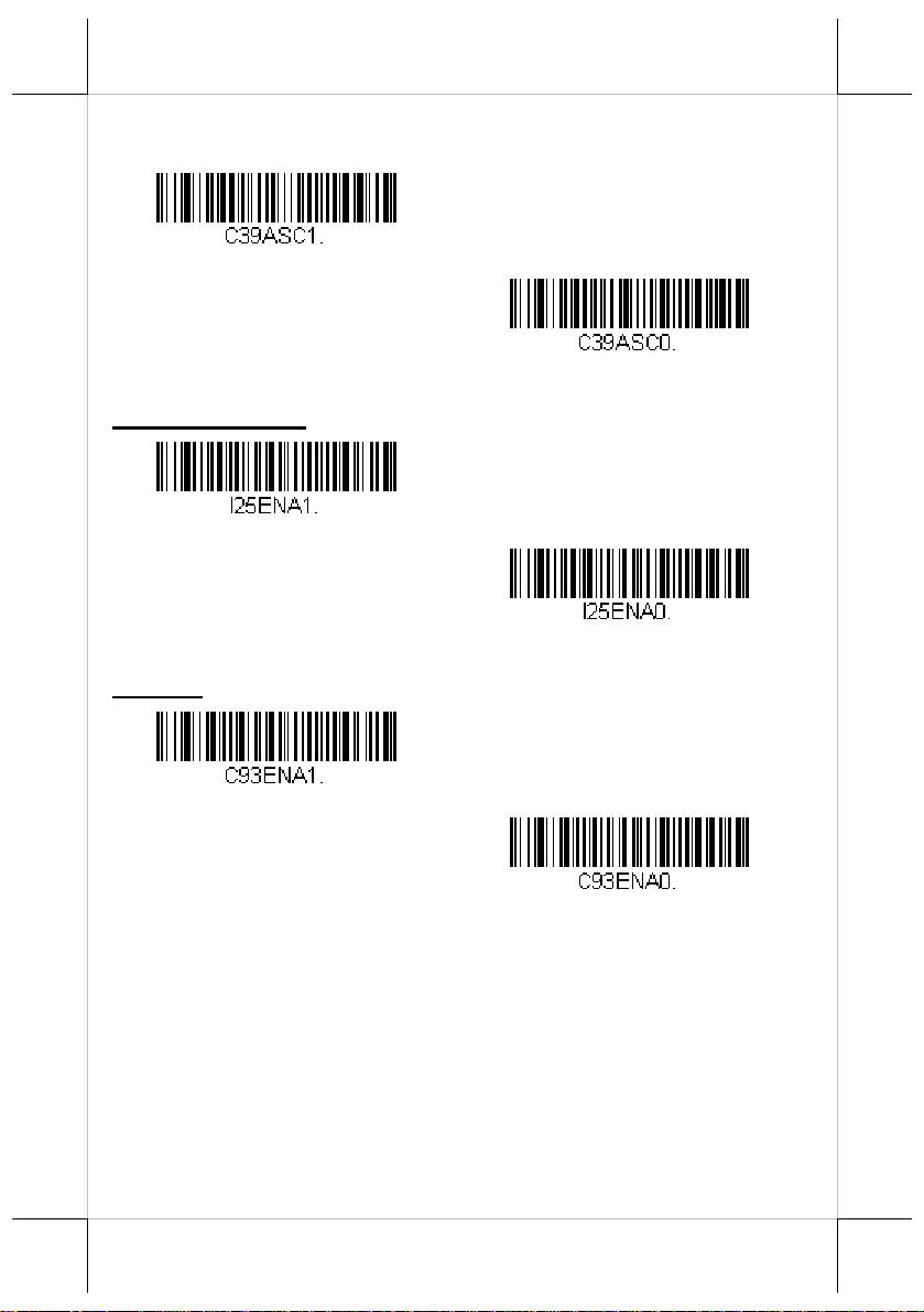
Full ASCII
If Full ASCII Code 39 decoding is enabled, certain character pairs
within the bar code symbol will be interpreted as a single
character.
For e xample, $V will be decoded as the ASCII character SYN, and
/C will be decoded as
NUL %U DLE $P
SOH $A DC1 $Q ! /A 1 1 A A Q Q a +A q +Q
STX $B DC2 $R “ /B 2 2 B B R R b +B r +R
ETX $C DC3 $S # /C 3 3 C C S S c +C s +S
EOT $D DC4 $T $ /D 4 4 D D T T d +D t +T
ENQ $E NAK $U % /E 5 5 E E U U e +E u +U
ACK $F SYN $V & /F 6 6 F F V V f +F v +V
BEL $G ETB $W ‘ /G 7 7 G G W W g +G w +W
BS $H CAN $X ( /H 8 8 H H X X h +H x +X
HT $I EM $Y ) /I 9 9 I I Y Y i +I y +Y
LF $J SUB $Z * /J : /Z J J Z Z j +J z +Z
VT $K ESC %A + /K ; %F K K [ %K k +K { %P
FF $L FS %B , /L < %G L L \ %L l +L | %Q
CR $M GS %C - - = %H M M ] %M
SO $N RS %D . . > %I N N ^ %N n +N ~ %S
SI $O US %E / /O ? %J O O _ %O o +O DEL %T
the ASCII character #. Default = Off.
SP
SPACE
0 0 @ %V P P ‘ %W p +P
m
+M } %R
5
Character pairs /M and /N decode as a minus sign and period
respectively.
Character pairs /P through /Y decode as 0 through 9.
Full ASCII On
Interleaved 2 of 5
* On
Code 93
* On
* Full ASCII Off
Off
Off
6

Matrix 2 of 5
Code 11
Code 128
On
* Off
On
* Off
* On
Off
GS1-128
* On
Off
7

Telepen
On
UPC-A
* On
Convert UPC-A to EAN-13
* Transmit UPC-A as UPC-A
* Off
Off
Transmit UPC-A as EAN-13
8

UPC-A Addenda
This selection adds 2 or 5 digits to the end of all scanned UPC-A
data.
Default = Off for both 2 Digit and 5 Digit Addenda.
2 Digit Addenda On
* 2 Digit Addenda Off
5 Digit Addenda On
* 5 Digit Addenda Off
UPC-A Addenda Required
When Required is scanned, the engine will only read UPC-A bar
codes
that have addenda. You must then turn on a 2 or 5 digit
addenda. Default = Not Required.
Required
* Not Required
9

UPC-E0
Most U.P.C. bar codes lead with the 0 num ber system. To read
these codes, use the UPC-E0 On selection. If you need to read
codes that lead with the 1 number system, use EAN/JAN-13.
Default = On.
EAN
EAN
* UPC-E0 On
/JAN-13
/JAN-8
UPC-E0 Off
* On
Off
* On
10
Off

MSI
On
GS1 DataBar Omnidirectional
* On
GS1 DataBar Limited
* On
* Off
Off
GS1 DataBar Expanded
* On
Off
Off
11

China Post (Hong K o ng 2 of 5)
On
* Off
Data Editing
Prefix/Suffix Overview
When a bar code is scanned, additional informatio n is sent to the
host computer along with the bar code data. This group of bar
code data and additional user-defined data is called a “message
string.” The selections in this section are used to build the user-
12
defined data into the message string.
Prefix and Suffix characters are data
characters that can be sent before and
after scanned data. Yo u can specify if
they should be sent with all
symbologies, or only with specific
symbologies.
The following illustration shows the break-down of a message
string:
Points to Keep In Mind
It is not necessary to build a message string. The selections
in this chapter are only used if you wish to alter the default
settings. Default prefix = None. Default suffix is dependent
on interface.
A prefix or suffix may be added or cleared from one
symbology or all symbologies.
You can add any prefix or suffix through ASCII Conversion.
You can string together several entries for several
symbologies at one
time.

Enter p refixes and suffixes in the order in which you want
them to appear
W hen setting up for specif ic symbologies (as op posed to all
on the output.
symbologies), the specific symbology ID value counts as an
added prefix or suffix character.
The m aximum size of a prefix or suffix configuration is 32
characters, which includes header information.
To Add a Prefix or Suffix:
Step 1: Scan the Add Prefix or Add Suffix symbol.
Step 2: Determine the 2 digit Hex value from the Symbology
Chart
(included in the Symbology Charts) for the
symbology to which you want to apply the prefix or
suffix. For example, for Code 128, Code ID is “j” and
Hex ID is “6A”.
Step 3: Scan the 2 hex digits from the Programming Chart inside
the back cover of this manual or scan 9, 9 for all
symbologies.
Step 4: Determine the hex value from the ASCII Conversion Chart
for the prefix or suffix you wish to enter.
Step 5: Scan the 2 digit hex value from the Programming Chart
inside the back cover of this manual.
Step 6: Repeat Steps 4 and 5 for every prefix or suffix character.
Step 7: To add the Code I.D., scan 5, C, 8, 0.
To add AIM I.D., scan 5, C, 8, 1.
To add a backslash (\), scan 5, C, 5, C.
Note: To add a backslash (\) as in Step 7, you must scan 5C twice
– once to create the leading backslash and then to create
the backslash itself.
Step 8. Scan Save to exit and save, or scan Discard to exit without
saving. Repeat Steps 1-6 to add a prefix or suffix for
another symbology.
13

Example: Add a Suffix to a specific symbology
To send a CR (carriage return)Suffix for U.P.C. only:
Step 1: Scan Add Suffix.
Step 2: Determine the 2 digit hex value from the Symbology
Chart (included in the Symbology Charts) for U.P.C.
Step 3: Scan 6, 3 from the Programming Chart.
Step 4: Determine the hex value from the ASCII Conversion Chart
for the CR (carriage return).
Step 5: Scan 0, D fr om the Programming Chart.
Step 6: Scan Save, or scan Discard to exit without saving.
To Clear One or All Prefixes or S uffixes
You can clear a single pref ix or suffix, or clear all
prefixes/suffixes for a
symbology. If you have been entering
prefixes and suffixes for single symbologies, you can use Clear
One Prefix (Suffix) to delete a specific character from a
symbology. When you Clear All Prefixes (Suffixes), all the
prefixes or suffixes for a sym bology are deleted.
Step 1: Scan the Clear One Prefix or Clear One Suffix symbol.
Step 2: Determine the 2 digit Hex value from the Symbology
Chart (included in the Symbology Charts) for the
symbology from which you want to clear the prefix or
suffix.
Step 3: Scan the 2 digit hex value from the Programming Chart
or scan 9, 9 for all symbologies.
Yo ur change is automatically s av ed .
14

To Add a Carriage Return Suffix to All Symbologies
Scan the following bar code if you wish to add a carriage return
suffix to all
current suffixes, and then programs a carriage return suffix for all
symbologies.
symbologies at once. This action first clears all
Prefix Selections
Add Prefix
Clear All Prefixes
Suffix Selections
Add Suffix
Add CR Suffix All Symbologies
Clear One Prefix
Clear All Suffixes
Clear One Suffix
15

Utilities
Adding a Test Code I.D. Prefix to All Symbologies
This selection allows you to turn on transmission of a Code I.D.
before the decoded symbol ogy . This action first clears all current
prefixes and then programs a Code I.D. prefix for all symbologies.
This is a temporary setting that will be rem ov ed when the un it is
power cycled.
Add Code I.D. Prefix to All Symbologies (Temporary)
Symbology Charts
Note: “m” represents the AIM modifier character. Refer to International
Technical Specification, Symbology Identifiers, for AIM modifier
character
Prefix/Suffix entri es f or spe cif ic sy mbo lo gi es ove rri de t he u niv ers al (A ll
Symbologies, 99) entry.
Refer to the sections of Data Editing and Data Formatting for
information about using Code ID and AIM ID.
Linear Symbologies
Symbology
All Symbologies 99
Codabar ]Fm 0-1 a 61
Code 11 ]H3
Code 128 ]Cm 0, 1, 2, 4 j 6A
Code 32 Pharmaceutical
(PARAF)
Code 39 (supports Full ASCII
mode)
details.
AIM Honeywell
ID
Possible
modifiers
(m)
]X0
]Am 0, 1, 3, 4, 5, 7 b 62
ID
h 68
< 3C
Hex
16 17

AIM Honeywell
Symbology
TCIF Linked Code 39
(TLC39)
Code 93 and 93i ]Gm 0-9, A-Z,
EAN ]Em 0, 1, 3, 4 d 64
EAN-13 (including Bookland
EAN)
EAN-13 with Add-On ]E3
EAN-13 with Extended
Coupon Code
EAN-8 ]E4
EAN-8 with Add-On ]E3
GS1
GS1 DataBar ]em 0 y 79
GS1 DataBar Limited ]em
GS1 DataBar Expanded ]em
GS1-128 ]C1
2 of 5
China Post (Hong Kong 2 of ]X0
Interleaved 2 of 5 ]Im 0, 1, 3 e 65
Matrix 2 of 5 ]X0
NEC 2 of 5 ]X0
Straight 2 of 5 I ATA ]Rm 0, 1, 3 f 66
Straight 2 of 5 Industrial ]S0
MSI ]Mm 0, 1 g 67
Telepen ]Bm
UPC
UPC-A ]E0
ID
]L2
]E0
]E3
Possible
modifiers
(m)
a-m
0, 1, 2, 3, 8,
9, A, B, C
ID Hex
T 54
i 69
d 64
d 64
d 64
D 44
D 44
{ 7B
} 7D
I 49
Q 51
m 6D
Y 59
f 66
t 74
c 63

Symbology
UPC-A with Add-On ]E3 c 63
UPC-A with Extended
Coupon Code
UPC-E ]E0
UPC-E with Add-On ]E3
UPC-E1 ]X0
Add Honeywell Code ID
Add AIM Code ID
Add Backslash
Batch mode quantity
Programming Chart
ID
]E3
AIM Honeywell
Possible
modifiers
(m)
0
ID Hex
c 63
E 45
E 45
E 45
5C80
5C81
5C5C
5 35
1
2
3
4
18

6
8
A
5
7
9
B
C
D
19

E
Save
Reset
F
Discard
Note: If you make an error while scanning the letters or digits
(before scanning
Save), scan Discard, scan the correct
letters or digits, and Save again.
20
 Loading...