

PD – 7301/7311/7321 Series
Rev. Original
FCC Notes:
This equipment generates, uses, and can radiate radio frequency
energy and, if not installed and used in accordance with the
instructions manual, may cause interference to radio
communications. It has been tested and found to comply with
limits for a Class A digital device pursuant to subpart J of Part 15 of FCC Rules, which
are designed to provide reasonable protection against interference when operated in a
commercial environment. Operation of this equipment in a residential area is likely to
cause interference in which case the user at his own expense will be required to take
whatever measures to correct the interference.
Warranty Limits:
Warranty terminates automatically when any person other than the authorized
technicians opens the machine. The user should consult his/her dealer for the problem
happened. Warranty voids if the user does not follow the instructions in application of
this merchandise. The manufacturer is by no means responsible for any damage or
hazard caused by improper application.
About This Manual:
Posiflex has made every effort for the accuracy of the content in this manual. However,
Posiflex will assume no liability for any technical inaccuracies or editorial or other
errors or omissions contained herein, nor for direct, indirect, incidental, consequential
or otherwise damages, including without limitation loss of data or profits, resulting
from the furnishing, performance, or use of this material.
This information is provided “as is” and Posiflex Inc. expressly disclaims any
warranties, expressed, implied or statutory, including without limitation implied
warranties of merchantability or fitness for particular purpose, good title and against
infringement.
The information in this manual contains only essential hardware concerns for general
user and is subject to change without notice. Posiflex reserves the right to alter product
designs, layouts or drivers without notification. The system integrator shall provide
applicative notices and arrangement for special options utilizing this product. The user
may find the most up to date information of the hardware from web sites:
http://www.posiflex.com
All data should be backed-up prior to the installation of any drive unit or storage
peripheral. Posiflex will not be responsible for any loss of data resulting from the use,
disuse or misuse of this or any other Posiflex product.
All rights are strictly reserved. No part of this documentation may be reproduced,
stored in a retrieval system, or transmitted in any form or by any means, electronic,
mechanical, photocopying, or otherwise, without prior express written consent from
Posiflex Inc. the publisher of this documentation.
© Copyright Posiflex Inc. 2006
All brand and product names and trademarks are the property of their respective holders.
P/N: 19480900010
User’s Manual
or http://www.posiflex.com.tw
Part 1
BRIEF INTRODUCTION
INTRODUCTION
The PD-7301/7311/7321 is a pole mount customer display option
designed for Posiflex HT series hybrid POS terminals or PB-2200/4200
discrete systems. It is delivered in separate carton for HT or PB series and shall
be installed per instruction in this manual.
This documentation describes the features and requirements of the
product series of PD-7301/7311/7321, a graphic liquid crystal customer
display. It displays alphanumerical characters in 2 lines of 20 large sized
characters and is able to display in 4 lines of 26 alphanumerical characters per
line to show more information at a time. In this series, there are also models
capable of displaying 2 lines of 10 oriental language characters per line in
addition to the standard displaying capability. The alphanu merical characters
are formed in a 8 x 16 dot matrix for 2 x 20 display and in a 6 x 8 dot matrix
for 4 x 26 display, the oriental language characters are displayed in a format of
16 x 16 dot matrix.
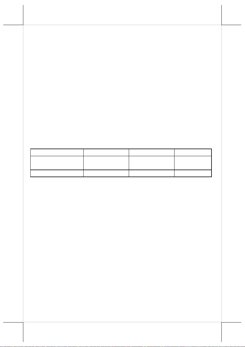
Display Capacity
Display Characters
Character Format
• Large character font size with backlight for easy readability and
comfort in short term and long term viewing
• Rear mount Pole Display for Posiflex HT series hybrid terminals
and PB-2200/4200 discrete systems.
• Large amount of information display for two lines of 20
alphanumeric characters per line or four lines of 26 alphanumeric
characters per line or two lines of 10 Chinese characters per line
• Adequately large characters for easy viewing (18.35 mm by 8.91
for alphanumerics/18.35 mm by 17.87 mm for Chinese)
• Wide operating temperature range (0°C to 50°C)
• Long life and trouble free operation
• 15°, 30° and 45° adjustable viewing angles
• Total height 510 mm above top surface of main unit of HT or PB
series
• Display frame can rotate horizontally 270° freely
• Various command emulation modes selectable by DIP switch
• US-ASCII Character (8 x 16 or 6 x 8 dot)
2 x 20 4 x 26 2 x 10
Alphanumerical Alphanumerical
8 x 16 6 x 8 16 x 16
Oriental
Language
FEATURES
Part 2
• Support 2 Code Pages of 128 characters each
• Support Chinese character GB-2312 or BIG-5 Character (16 x 16
dot)
• Support 12 international character sets of 12 characters each
• 3 User defined characters for PD-7301 and 2 User defined
characters for PD-7311/7321)
• Simple installation
• Software self test
• Serial (RS232) data interface
• Default protocol 9600, n, 8, 1
• Power obtained through interface cable
• Case color choices: ivory, charcoal
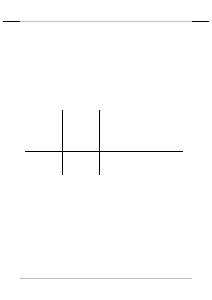
MODEL NUMBERS
Model Number PD-7301 PD-7311 PD-7321
Character Format 8 x 16 or 6 x 8
Display
Characters
Display Capacity 2 x 20 or 4 x 26
Command Set
User-defined
Characters
Alphanumerical
Noritake or
Epson
3 characters max. 2 characters max. 2 characters max.
16 x 16 or 8 x 16
or 6 x 8
GB-Chinese or
Alphanumerical
2 x 10 or 2 x 20
or 4 x 26
IEE or Noritake
or Epson
16 x 16 or 8 x 16
or 6 x 8
BIG-5-Chinese or
Alphanumerical
2 x 10 or 2 x 20
or 4 x 26
IEE or Noritake or
Epson
DESCRIPTION
This LCD is a self-contained multiplexed unit which provides a simple
interface to a microprocessor system.
The display is available with one I/O connector for both the RS232
interfacing and the power supply.
This unit consists of a liquid crystal display cell and a minimal amount of
electronic hardware. All display characters and control codes can be accessed
in a 8-bit format. Primary complexity is contained within the microprocessor
software, which controls all display functions.
Data is entered serially at 9600 baud rate as default and can be changed to
19200 baud rate per jumper setting. The large characters are easily readable,
and provide comfortable short or long-term viewing.
APPLICATION
This unit may be used as a console display which provides alphanumeric
Part 3

m
information that is easily readable in wide range of ambient light. It is ideal
for point-of-sale terminals, and a wide range of business and industrial
equipment.
INSTALLATION GUIDES
HOST SYSTEM PREPARAION
For serial interface (RS232) PD-7301/7311/7321 to be used in HT or
PB series, you have to adjust during power off the internal jumper of the host
system to supply 5 V DC to the COM port selected for PD-7301/7311/7321.
Locating holes
on I/O plate
Screw hole on
sidewall
Installation holes
on botto
facing the HT or PB system from its back) on bottom of the chassis as in the
left picture.
7301/7311/7321 in HT or PB
system, you have to open the back
cover according to the Users’
Manual of HT or PB system and
find the necessary holes for
installation of PD-7301/7311/7321
near the right corner (as you are
POLE DISPLAY BASE UNIT
To install PD-7301/7311/7321 to the HT or PB system, please take
Base unit
Locating bosses
to I/O plate
This side
against sidewall
Bottom
locking lugs
PD-7301/7311/7321 out of its box and observe
its base unit as in the left picture.
Please note at the bottom edge there
are 2 extruding lugs, on 1 side of bottom part
there are 2 extruding cylindrical bosses to
match in the holes on I/O plate of the HT or
PB system and on another side there are screw
holes to fit to the sidewall of HT chassis.
OPENING THE TOP COVER OF HT SERIES
For ease of PD-7301/7311/7321 installation operation,
the main unit has to be opened with sufficient precaution s. First
turn the display panel to straight up position. Prepare enough
space in front of the HT system and lay a piece of clean soft
clothe of appropriate size there to prevent damage. With the
back cable cover opened, push in the circled spring button in the
right picture on both sides of chassis and raise the rear edge of the top cover.
FIXING THE POLE DISPLAY
Insert the 2 bottom locking lugs into the 2 rectangular installation
holes on bottom of HT or PB chassis from the right corner and push the base
For installing PD-
Part 4

PD-73X1 Base
Fixing screw
tube of PD-7301/7311/7321 close against the
side wall of HT or PB chassis. Match the 2
cylindrical locating bosses into 2 round holes
in the I/O plate. The side of PDHT or PB
chassis sidewall
7301/7311/7321 base with the screw holes
shall face against the sidewall of HT or PB
system chassis. Use the self-tapping screw that comes with PD7301/7311/7321 to fix from external side of sidewall as demonstrated in the
above picture. Carefully close back the top cover of HT or PB system and
connect the interface cable of PD-7301/7311/7321 to appropriate port in HT or
PB connector area. Then close the back cover of HT or PB system. Please
reserve the pole hole cover from the back cover for future use.
COMMAND EMULATION MODE SETUP
On control board in display head
Now please check the back of PD-7301/7311/7321 display head as in
the right picture above. There is a small piece of plastic cover for the “DIP
switch window”. Slide the cover downward but don’t pull it off otherwise you
may have to practice for inserting it back. You can find 2 positions of DIP
switches in this window. Adjust for the appropriate comman d mode used by
the application program according to below table if required. Switch position
counts from left to right and “ON” means pushed up as indicated in the left
picture above.
SW2
SW1
OFF Epson 2 x 20 Noritake 2 x 20
ON Epson 4 x 26 IEE (Chinese) 2 x 10
The factory default command mode for PD-7301 is set to Noritake
mode. If the switch is set to IEE mode for PD-7301 all “Chinese characters”
will be displayed in full dots since it is not applicable. The factory default
command mode is set to IEE mode for both PD-7311 and PD-7321.
DIP switch
window
OFF ON
Part 5

RS232 protocol (Inside display head)
Short Open
JP1 19200, n, 8, 1 9600, n, 8, 1 (default)
DRIVER INSTALLATION
For application software to use RS232 interfaced PD-7301/7311/7321,
there is no direct need for any driver. The OPOS (OLE POS) driver or the
JPOS (Java POS) driver does not support the PD-7301/7311/7321 series.
COMMAND CODES
For software command codes application. Please visit our web site
http://www.posiflex.com or http://www.posiflex.com.tw for details on
software commands if required.
AFTER POWERING UP
A two-row message as power on sign will appear on the screen for a
while. Then a under-line cursor will appear at the left-most digit of the top row
for IEE emulation mode and no cursor will appear for other emulation modes.
The installation is now completed. Noritake and
Part 6

SPECIFICATION
OPTICAL
Number of characters Alphanumeric: 20 characters/row, 2 rows
Alphanumeric: 26 characters/row, 4 rows
Chinese: 10 characters/row, 2 rows
Dot matrix format 8 x 16 or 6 x 8 dots for alphanumeric
16 x 16 for Chinese
Character height 2 row alphanumeric: 18.35 mm
4 row alphanumeric: 9.15 mm
Chinese: 18.35 mm
Character width 2 row alphanumeric: 8.91 mm
4 row alphanumeric: 6.67 mm
Chinese: 17.87 mm
LCD type STN-blue with backlight
Effective display area 179.15 (W) x 36.75 (H) mm
Total display dots 160 (W) x 32 (H)
Dot size 1.07 (W) x 1.10 (H) mm
Dot pitch 0.05 (W) x 0.05 (H) mm
Viewing angle 60º (Vertically), 50º (Horizontally)
Response time 200/250 ms (typical)
MECHANICAL
Total Height (above HT or PB)
510 mm
Display Head Height 75 mm
Display Head Width 256 mm
Display Head Depth 64 mm
Case color Charcoal or Ivory
ELECTRICAL
Power from interface port of HT system: + 5VDC 1A
International Character Sets: USA; France; Germany; UK; Denmark
I; Sweden; Italy; Spain; Japan; Norway; Denmark II; Ex-Jugoslavia
Font Pages:
Operating temperature 0° to + 50°C
Storage temperature -20° to + 70°C
Operating humidity 20% to 85%, non-condensing
Storage humidity 5% to 90%, non-condensing
WARNING: If the user opens the pole display housing to make any
modification, all the product warranty will be voided.
Page 0 (PC437: USA); Page 1 (Katakana)
ENVIRONMENTAL
Part 7

USING THE CUSTOMER DISPLAY
DISPLAYING DATA
All data in 8-bit format received can be classified into 2 categories as
data to display or command codes for the customer display unit to respond. For
this series, unless under pass through mode or as part of the command code,
any byte between and including <20>h and <FF>h is regarded as
alphanumerical data to display according to ASCII table (the <XX>h means
the hexadecimal expression). The command codes except the clear pass
through flag command in Noritake mode always start with a byte between and
including <00>h and <1F>h. For PD-7321an d PD-7311, the command codes
follow the same rule as PD-7301, however, only those between and including
<20>h and <7F>h are taken as alphanumerical data to display according to
ASCII table in 8 x 16 format. Any two bytes with the first byte between and
including <80>h and <FF>h are regarded as the expression for an oriental
language character. When these two bytes fall off the content of the valid
oriental language code table, an invalid character will be displayed.
COMMAND MODE SELECTION GUIDE
The below table provides some comparison for selection on command
mode to be used in the application program if it is not yet determined. The list
of commands available in each mode can be found in the appendix.
Mode Epson Noritake IEE
Cursor Invisible Under Bar Under Bar
Default mode Overwrite Overwrite Horizontal scroll
User defined font 3 chars 3 chars 2 chars (Chinese)
Code page select YES YES NO
Auto scroll message NO YES NO
DRIVER INSTALLATION
For application software to use RS232 interfaced PD-7321, there is no
direct need for any driver. The OPOS (OLE POS) driver or the JPOS (Java
POS) driver does not support the PD-7321 series.
SELF TEST
Self-test is a very useful feature and can be activated in both Epson
command emulation modes and IEE mode. The self-test starts by sending 1F40 (HEX) and terminates by sending 1B-40 (HEX).
In IEE mode, the test sequence is as follows
a. Clear screen, Cursor home. The PD enters Vertical Scroll Mode.
b. PD shows the power-on message, language type and version.
c. The PD shows and enters “Horizontal Scroll” mode. Then displays
Part 8

20 CHINESE characters (addresses: B0A1, B1A2, B2A3, ……,
BEAF, BFB0, C0B1, ……, C3B4) one by one in bottom row.
d. The PD then shows and enters “Wrap Around Mode” and shows
ASCII code font from 21 to 7F (HEX) starting from Home position.
e. The PD enters and shows “Vertical Scroll Mode” and go to step a
and repeat the test
In Epson mode, the test sequence is as follows
a. Clear screen, Cursor home.
b. The PD enters and shows “VERTICAL SCROLL MODE”, the
power on message in applicable display format (2 rows or 4 rows),
language type, version and a message “OVERWRITE MODE”.
c. The PD then enters OVERWRITE MODE and displays 20
characters of “A” from home position. Then 20 characters of “B”
also from home position for 2 rows format or from beginning of 2
row for 4 rows format.
d. Clear screen, Cursor home.
e. The PD shows and enters “HORIZONTAL SCROLL” mode, then
displays ASCII code font of current page from 21 to FF (HEX) in
nd
2
row.
f. Go to step a and repeat the test
nd
Part 9

警告使用者
這是甲類的資訊產品,在居住的環
境中使用時,可能會造成射頻干
擾,在這種情況下,使用者會被要
求採取某些適當的對策。
T144
Part 10
 Loading...