

PD2500 Series
USER’S MANUAL
Rev. : A3
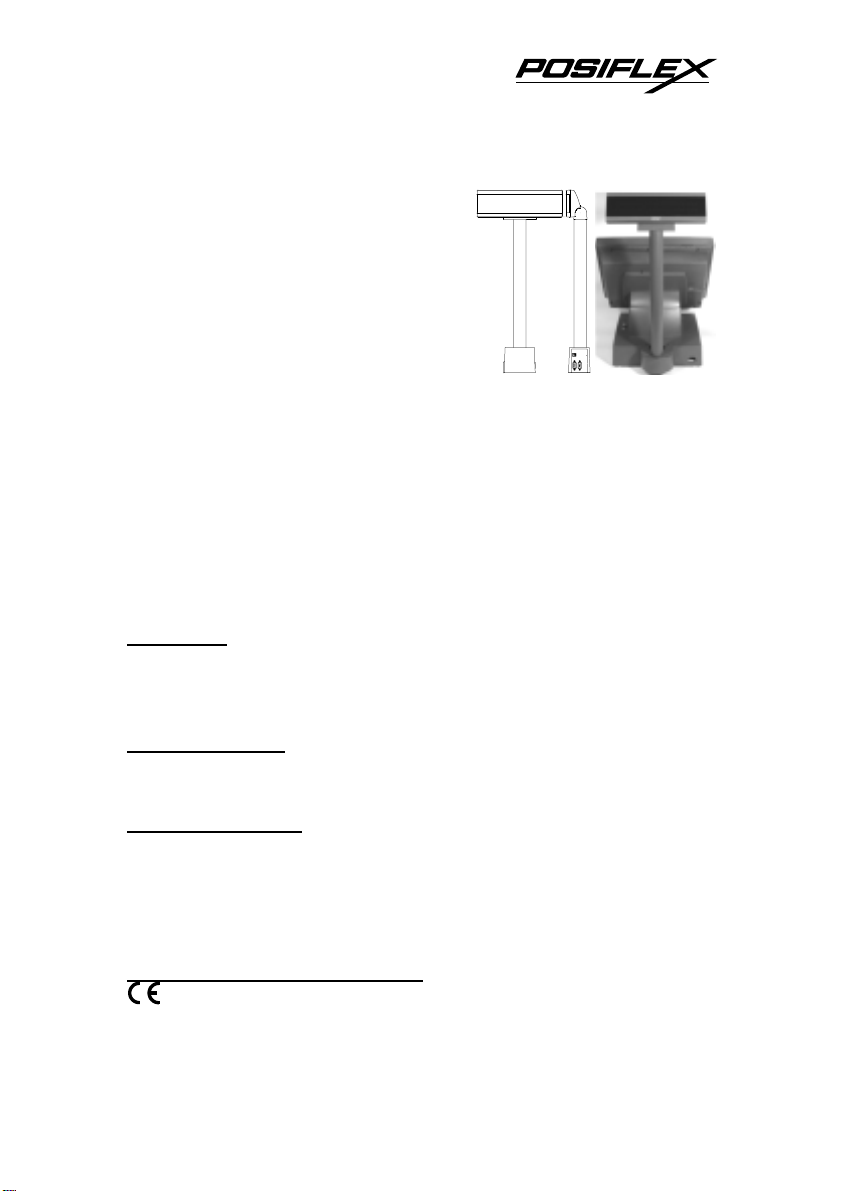
VFD CUSTOMER DISPLAY
for ALPHANUMERICAL DISPLAY
in 2 x 20 format
I. FEATURES
Stand-alone Pole Display with a mount plate and small base size with a
rock power ON/OFF switch on base (PD2500). Rear mount Pole
Display for Posiflex Jiva XL series touch terminals (PD2501)
Euro dollar sign supported in code page 858
Various command emulation modes selectable by DIP switch
Total height 556mm above mounting plate with a strong, stable pole
0° to 45° tilt in four steps and 300° swivel for best viewing effect
Cabinet color choices: ivory, charcoal
FCC NOTICE
accordance with the instructions manual, may cause interference to radio communications. It has been tested and found to
comply with limits for a Class A digital device pursuant to subpart J of Part 15 of FCC Rules, which are designed to
provide reasonable protection against interference when operated in a commercial environment. Operation of this
equipment in a residential area is likely to cause interference in which case the user at his own expense will be required to
take whatever measures to correct the interference.
WARRANTY LIMITS
technicians. The user should consult his/her dealer for the problem happened. Warrant y voids if the user does not follow
the instructions in application of this merchandise. The manufacturer is by no means responsible for any damage or
hazard caused by improper application.
ABOUT THIS MANUAL
versatile font formats and support various instruction sets. These series of products receive instructions in serial
communication protocols and is capable of entering pass through mode so that all instructions received pass on to next
connected serial device if properly configured.
modify this manual without notice due to the rapid and constant progress and improvement on science and technology.
The user may always obtain the most up to date information through any of our web sites: http://www.posiflex.com.tw,
http: //www.posiflexuk.com, http://www.posiflexusa.com.
TRADE MARKS AND SERVICE MARKS
owners.
This equipment generates, uses, and can radiate radio frequency energy and, if not installed and used in
Warranty will terminate automatically when the machine is opened by any person other than the authorized
This manual assists the user to utilize the VFD customer display PD2500 series. Theses series provide
The manufacturer of the PD-2500 series heartily apologizes to the user for reserving the right to c hange or to
POSIFLEX is a registered trademark of Mustek Corp..
Other brand and product names are trademarks and registered trademarks and service marks of thei r respective
Copyright Mustek Corp. 2002
P/N: 19450900020
1
w
r
r
II. MODELS
Case
Color
Beige Green
Charcoal Green
Beige Blue
Charcoal Blue
Display
Color
Standard, with AC
power adaptor per
country
PD2500/XX PD2500 PD2501
PD2500/XX-C PD2500-C PD2501-C
PD2500/XX-D PD2500-D PD2501-D
PD2500/XX-F PD2500-F PD2501-F
Option, for power
from PC I/O plate
For rear mount on
Posiflex Jiva XL
touch terminals
III. INSTALLATION
1. For all PD2500 & PD2501: Please set DIP SW on back of the display unit
of PD2500/PD2501 according to the appropriate emulation mode and the
instructions in next section.
2. For all PD2500: Mount the pole display stand plate
to the metal plate of base cabinet with screws and
mount the pole display stand plate to the bottom of
your Posiflex cash drawer CR3100/CR3200 series
as in the drawing or on the cashier’s dash. Connect
the pass through device to 9 pin male connector at
side of PD2500 base if required.
3. For PD2500 with power adaptor only: Use the attached interface cable
20863035900 (CCBLA-359) to connect the 9 pin female connector at side of
the base of PD2500 to the 9 pin male connector for serial port such as COM1
of the host PC. Check the specification of power adapter on its nameplate.
Check the power switch on base of PD2500 should be turned off. Insert the
power adaptor into the right power outlet. Insert the output plug to the jack
above the 9 pin D connector at one side of PD2500 base.
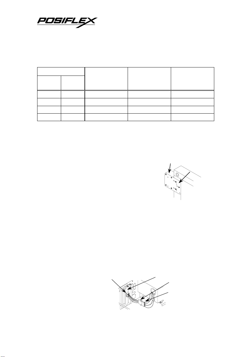
4. For PC powered PD2500 only: Open the case of a PC per its instruction
manual. Take the attached assembly coded 20867014100 (or known as
CCBLA-141) and install
the I/O plate to one of the
I/O windows in PC. Then
connect it to one of the
power connectors from
Base cabinet
Bottom vie
of cash drawer
I/O plate of CCBLA - 141 4 pin telephone jack
CCBLA - 141
4 pin power connecto
from switching powe
supply unit
Stand plate
2

the power supply unit of the PC. Check the power switch on base of PD2500
should be turned off. Connect the 4 pin plug of cable 20863041100 to the
jack in the I/O plate and connect the power plug to the jack above the 9 pin
D connector at one side of PD2500 base. Use the attached interface cable
20863035900 (CCBLA-359) to connect the 9 pin female connector at side of
the base of PD2500 to the 9 pin male connector for serial port such as COM1
of the host PC.
5. For Posiflex POS powered PD2500: Adjust the internal jumper of the
Posiflex POS system to supply 5 V DC to the selected COM port. Use the
attached interface cable 20863037200 (CCBLA-372) to connect the 9 pin
female connector at side of the base of PD2500 to the 9 pin male connector
for serial port of the Posiflex POS system.
6. For Posiflex Jiva XL powered PD2501: Adjust the internal
jumper of the Posiflex Jiva XL system to supply 5 V DC to the
COM port connected. Open the rear connect area and assemble
the base of PD2501 into the opening according to the instruction given for
Jiva XL. Connect the 9 pin female connector of the cable coming from
bottom of PD2501 to the 9 pin male connector for serial port of the Jiva XL.
7. For all PD2500 & PD2501: Turn on the Jiva XL, Posiflex POS system, the
PC connected and the power switch of PD2500 models, a firmware version
as power on sign will appear for a while to indicate that PD2500 is tested
O.K. and ready to work.
IV. COMMAND EMULATION
This customer display supports totally 6 emulation modes. The emulation
mode is selected by adjusting when power turned off the BIT 3, 4 and 5 of the
DIP SW1 on the back according to this table. It is turned ON when pushed up.
Mode UTC Aedex Noritake Epson Futaba ADM
SW1 BIT 3
SW1 BIT 4
SW1 BIT 5
This unit is set to Noritake mode as delivered. For more details of each
emulation mode, please refer to the Product Information CD or visit our web site
http://www.posiflex.com.tw
ON ON ON ON OFF OFF
ON ON OFF OFF ON ON
ON OFF ON OFF ON OFF
for latest updates.
3

V. SPECIFICATIONS
A. Optical
Number of digits 20 digits/row, 2 rows
Dot matrix 5 X 7 dots w/ period & comma
Digit height 11.25 mm
Digit width 7.2 mm
Display Area 193 mm x 39.4 mm
Display color Blue or Green
B. Mechanical
Weight 1.3 kgs (2.86 lbs) (excl. power adaptor)
Height 114 mm (incl. Mounting plate)
Width 260 mm
Depth 65.5 mm
C. Electrical
Power consumption: 5 W max.
Power supply:
Adaptors: I/P: 120VAC/60Hz or 220VAC/50Hz
O/P: 12VAC ± 5% heavy duty
PC power: 12 V DC
Interface power: 5 V DC
D. Environmental
Operating temperature 0°C to + 40°C
Storage temperature -20° to + 70°C
Operating humidity 20%RH ~85%RH, non-condensing
Storage humidity 5%RH ~90%RH, non-condensing
Vibration resistance 4 G max. (half amplitude 0.15mm)
Impact resistance 40 G, 11 ms wave, 5 times for each of
the X, Y and Z directions
WARNING: If the user opens the pole display housing to make any change, all
the product warranty will be voided.
NOTE: Please refer to Posiflex Product Information CD or visit our web
http://www/posiflex.com.tw
for further information when needed.
4
 Loading...