


Rev. : Original
MANUFACTURED BY:
POSIFLEX TECHNOLOGY, INC.
AN
ISO-9001
AND
ISO-14001
CERTIFIED MANUFACTURER
6,WU-CHUAN RD.,HSIN-CHUANG TEL: 886-2-2991599 (REP.) FAX: 886-2-2991819, 2991808
(WU-KU INDUSTRIAL ZONE) http://www.posiflex.com http://www.posiflex.com.tw
TAIPEI HSIEN, TAIWAN http://www.posiflexusa.com EMAIL: posiflex@posiflex.com.tw
HT-3200 /
PB-3200 SERIES
TECHNICAL MANUAL

SOME IMPORTANT NOTES
FCC NOTES
This equipment generates, uses, and can radiate radio frequency energy and, if not installed and used in
accordance with the instructions manual, may cause interference to radio communications. It has been
tested and found to comply with limits for a Class A digital device pursuant to subpart J of Part 15 of
FCC Rules, which are designed to provide reasonable protection against interference when operated in
a commercial environment. Operation of this equipment in a residential area is likely to cause
interference in which case the user at his own expense will be required to take whatever measures to
correct the interference.
WARRANTY LIMITS
Warranty will terminate automatically when the machine is opened by any person other than the
authorized technicians. The user should consult his/her dealer for the problem happened. Warranty
voids if the user does not follow the instructions in application of this merchandise. The manufacturer is
by no means responsible for any damage or hazard caused by improper application.
ABOUT THIS MANUAL
This manual assists the user especially the software programmer who provides the software system for
POS application to utilize the hardware of the HT-3200 & PB-3200 series which are members of the
POSIFLEX integrated point-of-sale terminal product family. The HT-3200 is a compact point-of-sale
system that gives the most user friendly application interface by providing a 12” touch control LCD
panel and combines the performance and affordability of personal computers with the elegance and
reliability of business machine. The PB-3200 is a derivation from HT-3200 with the 12” touch control
LCD panel removed to allow free discrete application. Both HT-3200 & PB-3200 series provide the
built-in networking capability for easy communication among multiple terminals in addition to the data
transfer and control through back office server.
The manufacturer of the HT-3200 & PB-3200 series heartily apologizes to the user for reserving the
right to change or to modify this manual without notice due to the rapid and constant progress and
improvement on science and technology. The user may always obtain the most up to date information or
software utilities through any of our web sites:
http://www.posiflex.com.tw; http://www.posiflex.com; http://www.posiflexusa.com
Copyright Posiflex Technology, Inc., 2010
All rights are strictly reserved. No part of this documentation may be reproduced, stored in a retrieval
system, or transmitted in any form or by any means, electronic, mechanical, photocopying, or otherwise,
without the prior written consent of Posiflex Technology, Inc. the publisher of this documentation.
TRADE MARKS AND SERVICE MARKS
POSIFLEX is a registered trademark of Posiflex Technology, Inc..
Other brand and product names are trademarks and registered trademarks and service marks of their
respective owners.

i
CONTENTS
OVERVIEW ....................................................................................................................................... 5
SCOPE............................................................................................................................................. 5
FEATURES ..................................................................................................................................... 5
OPTIONAL ITEMS......................................................................................................................... 6
GENERAL SPECIFICATION.......................................................................................................... 7
SYSTEM ......................................................................................................................................... 7
POWER SOURCE........................................................................................................................... 7
SYSTEM POWER ON/OFF CONTROL ........................................................................................ 8
12VDC POWER SUPPLY INTO SYSTEM.................................................................................... 8
OVERALL POWER OUTPUT LIMIT............................................................................................ 8
INPUT / OUTPUT PORTS.............................................................................................................. 8
TOUCH PANEL (F
OR
HT-3200 O
NLY
) .......................................................................................... 9
PRELOAD OS ................................................................................................................................. 9
OPERATOR DISPLAY (HT-3200
ONLY
) ....................................................................................... 9
LED INDICATOR IN LCD PANEL.............................................................................................. 10
EXTERIOR ................................................................................................................................... 10
ENVIRONMENTAL..................................................................................................................... 10
COMPLIANCE APPROVALS...................................................................................................... 11
OPTIONS ...................................................................................................................................... 11
SECOND DISPLAY ON BASE.................................................................................................. 11
CUSTOMER DISPLAY UPGRADE KIT ................................................................................... 12
DRAM EXPANSION ................................................................................................................. 12
UPGRADE KIT KP-200 for HT-3200....................................................................................... 12
SIDE MOUNT UPGRADE KIT SD300..................................................................................... 13
CASH DRAWER CONTROL CABLE........................................................................................ 14
WIRELESS LAN ........................................................................................................................ 14
SSD HDD .................................................................................................................................. 14
PRINTER: ................................................................................................................................. 14
RELIABILITY INFORMATION ................................................................................................... 17

ii
SYSTEM DEFINITIONS ................................................................................................................ 18
BLOCK DIAGRAM ...................................................................................................................... 18
12 V DC IN CONNECTOR ........................................................................................................... 19
LAN PORT .................................................................................................................................... 19
VGA CONNECTOR...................................................................................................................... 20
SERIAL PORT COM1................................................................................................................... 20
SERIAL PORT COM2/3/4 ............................................................................................................ 21
PARALLEL PORT LPT1 .............................................................................................................. 22
PS/2 KEYBOARD CONNECTOR................................................................................................ 23
PS/2 MOUSE................................................................................................................................. 23
USB0 / USB1 / USB2 / USB3 / USB4 / USB5 ............................................................................... 23
CASH DRAWER CONNECTER .................................................................................................. 24
APPLICATION GUIDES ................................................................................................................ 25
POWER SUPPLY TO I/O PORTS ................................................................................................ 25
COM1 APPLICATION COMMENT ............................................................................................ 25
CASH DRAWER........................................................................................................................... 25
PS/2 INTERFACE DEVICE.......................................................................................................... 26
EXTENDED DUAL DISPLAY MODE ........................................................................................ 26
CUSTOMER DISPLAY ................................................................................................................ 27
UPS BATTERY............................................................................................................................. 27
UPS BATTERY HEALTH CHECK.............................................................................................. 28
POWER ON/OFF CONTROL....................................................................................................... 29
HARDWARE POWER SWITCH................................................................................................ 29
SOFTWARE SWITCH OFF ...................................................................................................... 30
FORCED SWITCH OFF........................................................................................................... 30
AUTOMATIC POWER ON CONTROL....................................................................................... 32
ALARM CLOCK WAKE UP...................................................................................................... 32
MODEM RING UP ................................................................................................................... 32
LAN WAKE UP ......................................................................................................................... 33
FINGERPRINT SENSOR ............................................................................................................. 33
POSIFLEX TOOLS ....................................................................................................................... 34
POSIFLEX POWER SWITCH MANAGER ............................................................................... 34

iii
POSIFLEX MSR MANAGER .................................................................................................... 35
PROGRAMMABLE KEYPAD ................................................................................................... 38
POSIFLEX USB TOUCH MANAGER ...................................................................................... 40
HARDWARE DETAILS.................................................................................................................. 43
MAIN BOARD (HT-3200) ............................................................................................................ 43
COMPONENT SIDE................................................................................................................. 43
JUMPERS AND CONNECTORS .............................................................................................. 44
JUMPER SETTINGS................................................................................................................. 45
SERIAL ADAPTOR CARD HT-022............................................................................................. 47
JUMPERS AND CONNECTORS .............................................................................................. 47
JUMPER SETTINGS................................................................................................................. 47
LCD / TOUCH CONTROL CARD................................................................................................ 48
COMPONENT SIDE................................................................................................................. 48
SOLDER SIDE (HT-44) ............................................................................................................ 49
JUMPERS AND CONNECTORS .............................................................................................. 49
JUMPER SETTINGS................................................................................................................. 49
USB MSR CONTROL BOARD (SD320)...................................................................................... 50
COMPONENT SIDE................................................................................................................. 50
JUMPERS AND CONNECTORS .............................................................................................. 50
JUMPER SETTING................................................................................................................... 50
SERVICE AND SPARE PARTS..................................................................................................... 51
SERVICE GUIDE ......................................................................................................................... 51
DISCONNECT ALL CABLES ................................................................................................... 51
SIDE MOUNT UPGRADE KIT ................................................................................................ 51
SEPARATE LCD PANEL ASSEMBLY ...................................................................................... 51
INSIDE LCD PANEL ASSEMBLY ............................................................................................ 52
REINSTALL LCD PANEL ASSEMBLY ..................................................................................... 54
OPEN THE MAIN UNIT........................................................................................................... 55
POLE MOUNT UPGRADE KIT ............................................................................................... 55
2ND DISPLAY (LM-2010) .......................................................................................................... 56
COM 5/6 INSTALLATION ........................................................................................................ 57
EXTENDED PCI RISER CARD ................................................................................................ 58

iv
RELEASE SATA HDD .............................................................................................................. 59
2nd DISPLAY ADAPTOR BOARD (For PB-3200 only) ............................................................ 59
REPLACE MAINBOARD.......................................................................................................... 60
SPARE PARTS LIST ................................................................................................................. 60
SPARE PARTS LIST ................................................................................................................. 61
ASSEMBLY DRAWING............................................................................................................. 65

5
OVERVIEW
SCOPE
The Posiflex range of HT/PB-3200 terminals have been designed and manufactured to
meet the high end demand on POS systems. It incorporates all the advances of PC
technology within a rugged housing designed for use in a hostile retail environment.
By providing an integrated design, it has retained many of the secure features of a
traditional ECR and has avoided the wiring “spaghetti” associated with more
traditional PC solutions. This Open Standard Architecture ensures that this terminal
can use the PC application software and development tools that are now inexpensively
available and abundant.
For the HT-3200 series terminal is powered by most up to date CPU and provides a
color TFT LCD screen with a resistive type touch control panel on sturdy and easily
adjustable structure on top of the main unit. HT/PB-3200 series may be used as a self-
content unit or as one of several terminals in a network system controlled by a “back
office” computer through the integrated network interface. Versatile options besides
the basic model selection can apply to it as well.
FEATURES
CPU: Intel Atom N270 1.6G
RAM: DIMM socket x 2, DDR-2 533MHz, Max 2 GB
Data storage device: SATA HDD 2.5” or SDD HDD
Touch control functions: left/right button, double click, drag & draw( For HT-
3200 only)
Ethernet Networking: One LAN port Ethernet 10/100/1000 Base T with LAN
status indicators on jack (green for link, yellow for data transmission)
Serial Ports: There are 4 serial ports and another extendable 2 serial ports in
HT/PB-3200 system. +5V power supply for COM 2/3/4 by BIOS software setting;

6
+12V power on COM2/3/4 by jumper setting. The COM2/3/4 is default as no
power at delivery.
Parallel Port: Each HT/PB-3200 system is equipped with a parallel port that
supports SPP/EPP/ECP.
VGA Port: There is a VGA connector for connection of external monitor with +
12 V DC power supply included. It is default as no power at delivery.
USB Ports: The HT/PB-3200 series is equipped with 6 standard USB connectors
for connection of USB (Universal Serial Bus) devices.
PS/2 KB Port: 1 PS/2 KB port
PS/2 Mouse Port: 1 mouse port
CR Port: 1 CR port control 2 cash drawers max.
PCI Slot: 1 PCI extension slot.
Modem Ring-Up or LAN Wake-Up: The HT/PB-3200 series can be turned on
automatically upon an incoming COM port Modem call or LAN status or data
packet received on LAN. Please notice that when wake up by LAN or modem
ring up, HT/PB-3200 does not support EUP standard.
+12V of VGA port can be set up through BIOS control.
In accordance with EuP standard LOT 6.
OPTIONAL ITEMS
THE OPTIONAL ITEMS
Note: These items below must be installed by the qualified technician. Attempt to
apply them by end users is either too difficult or is likely to cause damages.
a) Data Storage: SSD kit
b) Wireless LAN Adaptor(Optional): USB interface, IEEE 802.11b/g
c) Preload OS: Win XP Pro, WEPOS, POSReady or Linux.
d) Support CRT2 through SDVO interface on PB-3200.
e) 2nd VGA ports for PB-3200: One for main Display and another one for second
display.
f) Optional COM 5/6 for additional peripherals.

7
g) SSD HDD
h) 2nd SATA HDD with RAID control board.
i) UPS battery.
GENERAL SPECIFICATION
SYSTEM
CPU: Intel Atom N270 1.6GHz.
RAM: DIMM socket * 2 ,DDR-2 533MHz ,Max 2 GB
2.5” HDD in SATA interface.
POWER SOURCE
DC power adaptor:
Item Specification
Voltage range of power input 100 ~ 240 V AC
Load limit of power input 2.5 A max.
Input frequency 47 ~ 63 Hz
Output voltage 12 V DC
Output current 5.0 A max.
System:
Total Power Consumption
Display used
Models
Normal Maximum
PB-3200
30 W
12.1” TFT LCD
HT-3200 24 W
60 W
System Standby Power (at power off mode): 0.36W (Not including Adaptor)

8
SYSTEM POWER ON/OFF CONTROL
One main power ON/OFF push switch at side, this switch can be
programmed as “ON” only
System can be waked up after each power off by any of the preset timer or
a remote COM port MODEM call or LAN wakeup packet. Please notice
that when wake up by LAN or modem ring up available, HT/PB-3200
does not support EUP standard. In other words, LAN or modem ring
up will not activate when EUP support available.
System can be switched off by software command through local or remote
program control
Forced power off when switch is ON/OFF or when switch is ON only with
prolonged effort
Power OFF to ON duration: 10 seconds minimum.
12VDC POWER SUPPLY INTO SYSTEM
O / P: 12 V DC, 5.0 Amp.
I / P : 115 VAC/ 1.2 A or 230 VAC/ 0.6A max., 47 ~ 63 Hz
OVERALL POWER OUTPUT LIMIT
Including COM 2/3/4 ports: + 5 V DC / 1 Amp max or +12V DC/ 1 Amp
max
All normal USB: 5 V DC / 500 mA each port.
VGA: +12 V DC/1 A
INPUT / OUTPUT PORTS
1 x mini DIN 6 pin female PS/2 KB jack
1 x mini DIN 6 pin female PS/2 mouse connector
1 x VGA display port for external monitor (for HT&PB-3200 ) or
additional 2nd (for PB-3200 ) display
1 x parallel port
1 x LAN port (Ethernet 10/100/1000 base T)

9
6 x USB ports
4 x serial communication ports. COM 2/3/4 each can supply DC +5V
through pin 9.
1 x CR port
1 x mini DIN 4 pin power input jack
Optional COM 5/6 ports
TOUCH PANEL (For HT-3200 Only)
Extremely endurable life survives minimum up to 35,000,000 touches at
same spot
Touch control interface: USB
Sensor type: resistive type
Touch resolution: 1024 x 1024
Calibration: initial calibration at setup only, no re-calibration required for
day to day power on/off
Driver support: Win XP, POSReady and Linux.
PRELOAD OS
Option among Win XP, WEPOS and POSReady.
OPERATOR DISPLAY (HT-3200 only)
Display Type COLOR TFT 12.1” LCD
View area 246 mm x 184 mm (9.7” x 7.3”)
Internal interface LVDS
Control knob Brightness
Resolution 1024 X 768
Memory size ? Support DVMT 5.0
Tilt angle 15° ~ 50°
Swivel angle 0° ~ 16° clockwise

10
LED INDICATOR IN LCD PANEL
Power ON / Standby LED: blue/orange dual color for system ON/OFF
status, external power status,
LAN status LED: yellow/green dual color for link, communication (green:
LAN link; steady green with flickering yellow: data transmission)
EXTERIOR
HT-3200 DIMENSIONS:
LCD @ 15°: 295 mm (W) x 263 mm (D) x 342 mm (H) or
11.6” x 10.4” x 13.5”
LCD @ 50°: 295 mm (W) x 258 mm (D) x 289 mm (H) or
11.6” x 10.2” x 11.4”
PACKING: 408 mm (W) x 338 mm (D) x 375 mm (H) or
16.1” x 13.3” x 14.8”
PB-3200 DIMENSIONS:
SYSTEM: 279 mm (W) x 243 mm (D) x 114 mm (H) or
11.0” x 9.6” x 4.5”
PACKING: 370 mm (W) x 317 mm (D) x 250 mm (H) or
14.6” x 12.5” x 9.8”
WEIGHT:
NET WEIGHT
HT-3200 Pro 5.2 kg (11.5 lbs)
PB-3200 Pro 3.3 kg (7.3 lbs)
ENVIRONMENTAL
TEMPERATURE RANGE (excl. UPS battery):
Operating: 0°C ~ +40°C or 32°F ~ 104°F
Non-operating: -20°C ~ +80°C or -4°F ~ +176°F
TEMPERATURE RANGE for UPS battery:
Operating: 0°C ~ +35°C or 32°F ~ 95°F
Non-operating: -20°C ~ +40°C or -4°F ~ +104°F

11
HUMIDITY RANGE:
Operating: 20%RH ~ 80%RH, non-condensing,
max. wet bulb 26°C (78.8°F)
Non-operating: 10%RH ~ 80%RH, non-condensing,
max. wet bulb 28.9°C (84.0°F)
COMPLIANCE APPROVALS
Whole system meet CE, FCC class A standard
(Meet IEC61000-4-2/-3/-4/-5/-6/-8/-11)
Power supply is UL, VDE approved
RoHS
OPTIONS
SECOND DISPLAY ON BASE
MODEL Number LM2010
Display Type Color TFT 10.4"
View Area (mm) 211.2 x 158.4
Interface VGA
Internal Interface 1 channel LVDS
Luminance 230 cd/m2 typ.
Backlight CCFL x 1
Contrast Ratio 500 : 1
Resolution 800 x 600 (SVGA)
Color Depth 16 bits true color (262,144)
Tilt Angle Stand straight (as 0°) to backward till touching main unit
Swivel Angle N. A.
Power Source DC 12 V in VGA
12
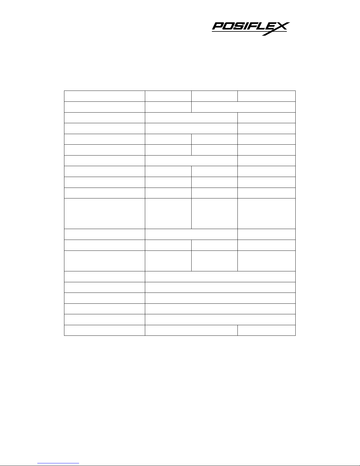
CUSTOMER DISPLAY UPGRADE KIT
MODEL Number PD-2601/U PD-307/U PD-7621
Display Media VFD LCD
Number of rows 2 4
Characters per row 20 15 or 30
Character width (mm) 5.25 6.0 4.27 or 8.47
Character height (mm) 9.03 9.66 8.47
Character format 5 X 7 8 x 16 or 16 x 16
Character code pages 14 1 1
International character sets
12 1 1
Command modes 6 2 1
Display color
Green w/ Blue
or Green filter
Dark blue /
Yellow green
background
White / Blue
background
Contrast adjust N. A. 2 buttons
Display area (mm x mm) 157.05 x 22.86 142.8 x 20.64
127.16 x 33.88
Display head size (mm) 197 x 56 x 58
196.7 x 57.5 x
39.6
212.7 x 78.5 x 43.5
Mounting method Pole mount on base
Pole height (mm) 200
Horizontal slide (mm) N. A.
Horizontal rotation 270º
Inclined viewing angle 15º, 30º, 45º
Power source 5 V DC in DB9 or USB 5 V DC in DB9
DRAM EXPANSION
DDR2 SDRAM DIMM in 2 sockets up to total 2 GB max.
UPGRADE KIT KP-200 for HT-3200
To be installed to right side of HT series LCD panel

13
Functions include: 36 keys + key-lock programmable keypad,
MSR, smart card reader
Interface: USB
PROGRAMMABLE KEYPAD:
1. 1 electronic 6-position control key to lock up or determine
among 5 different pages of programmable keys
2. 16 key numeric keypad with a double sized “Enter” key
3. 20 programmable single keys of size 19 x 19 mm
MAGNETIC STRIPE READER:
1. Reader head options: ISO 2 tracks (track 1 + track 2); ISO 3
tracks (track 1 + track 2 + track 3)
2. Characteristic parameters of ISO readers can be set via software
3. AAMVA/CA DMV format supported in ISO 3 tracks model
SMART CARD READER:
1. PC/SC 1.0 standard, EMV level I
SIDE MOUNT UPGRADE KIT SD300
To be installed to right side of HT series LCD panel
Functions include: MSR, optical type finger print sensor
Interface: USB
MAGNETIC STRIPE READER:
1. Reader head options: ISO 2 tracks (track 1 + track 2); ISO 3
tracks (track 1 + track 2 + track 3)
2. Characteristic parameters of ISO readers can be set via software
3. AAMVA/CA DMV format supported in ISO 3 tracks model
OPTICAL FINGERPRINT SENSOR:
1. Detection area : 14.6 x 18.1 mm (nominal at center)
2. Gray scale : 8 bits (256 levels)
3. Resolution : 512 dpi (average x, y over the field)

14
CASH DRAWER CONTROL CABLE
2 in 1 cash drawer control cable 20863023400 for independent
control over two cash drawers of CR-2200 /CR-3100 /CR-3200
/CR-4000 /CR-4100 /CR-6310
WIRELESS LAN
IEEE 802.11b/g with USB interface
SSD HDD
2.5” SATA interface
SSD can’t coexist with HDD in main unit
PRINTER:
PP-2000
1. 2-station receipt/journal/validation printer
2. Dot matrix 9 pin
3. Bi-directional printing
4. Auto cutter provides full cut and partial cut
5. Auto-detect between RS232 and EPP interface
PP-5200
1. High speed thermal line printer up to 220 mm/sec
2. High-resolution printing 8 dots/mm and 432 dots/line
3. Supports application environment of DOS, Windows, OPOS or
WEPOS
4. Low noise high reliability
5. Drop-and-load structure for paper roll loading
6. Easy print head cleaning
7. Guillotine type Auto cutter provides paper partial cut and a
manual cut
8. 10 KB input butter

15
9. Built-in character registration function with 256 KB flash
memory for downloading and storing special character pattern
or graphics for store logo
10. Supports option either alarm type or buzzer type kitchen alarm
PP-5600
1. Dot matrix impact 9 pin
2. Bi-directional printing
3. Friction feed type
4. 40 columns for 16.9 CPI
5. Accepts paper width 3 inches (76 mm)
6. Prints on ordinary or up to 3-fold carbonless copy paper
PP-5700
1. Dot matrix 9 pin
2. Bi-directional printing
3. Sprocket feed type
4. 2 models for single pass or double pass print of Chinese
characters
5. 4.4 lines per second for single pass or 2.2 lines per second for
double pass print
6. 8 KB input buffer
7. 40 columns (20 columns Chinese) or 35 columns (17 columns
Chinese)
PP-6800 series
1. Paper jams can be solving by push the “Hood Release Button”
directly.
2. Fast-speed printing (150mm per second).
3. Supports application environment of Windows or OPOS or
Linux.
4. Low noise thermal printing.
5. Drop-and-load structure for paper roll loading.
6. Cash drawer control up to 2 cash drawers.
7. Supports enhancement capability in kitchen bell for reminder
function.

16
8. Default with serial interface, option for parallel, USB, WI-FI or
LAN interface by plug in module.
PP-8000
1. Supports UPOS 1.8
2. WEPOS compliant
3. High speed thermal line printer up to 220 mm/sec
4. High resolution 8 dots/mm by 512 dots/line (576 dots max.)
5. Epson TM-T88 IV compatible command set
6. Low noise high reliability
7. Auto guillotine type cutter provides single point left partial cut
8. Thermal sensitive paper roll at width 80 mm or 58 mm
9. Supports UPC-A, EAN(JAN)13/8, ITF, CODE39, CODABAR
printing
10. Supports printing on label with marker on the other side
11. Supports option spill protect cover
12. Supports option either alarm type or buzzer type kitchen alarm
PP-8000L
1. LAN interface
2. All other features same as PP8000
PP-8000U
2. USB interface
3. All other features same as PP8000

17
RELIABILITY INFORMATION
TOUCH PANEL LIFE EXPECTANCY (TOUCHES AT SAME SPOT):
RESISTIVE TYPE: 35,000,000 UP
MSR LIFE EXPECTANCY: 500,000 PASSES
WHOLE SYSTEM MTBF: 50,000 Hrs at 90% confidence level.

18
SYSTEM DEFINITIONS
BLOCK DIAGRAM
SATA
HDD
(+5V
/+12V)
PCI slot SATA
Intel Atom N270
1.6G CPU
Intel 945GSE
(NB)
PSU Circuit
12 V DC
Adaptor
CR3/4/6
X00
PWR
MNGR
CR
LM-2010
VGA
Port
(+12V)
DDR2 533
DIMM
Touch
Controller
LCD
Signal
Touch Panel
LCD Panel
(1st screen for HT series)
LCD & Touch Connector
ICH7M
(SB)
PS/2
Mouse
PS/2
Mouse Port
PS/2
KB
PS/2 KB
Port
USB
Devices
USB
1/3/5
Ethernet
10/100/100
0 MB
LAN
Chip
USB
Devices
USB
0/2/4
COM2
RS232
Device
RS232
Device
COM1
LPT
Parallel
Port
COM6
RS232
Device
COM5
RS232
Device
(HT-022)
COM3
RS232
Device
COM4
RS232
Device
(+5V
/+12V)
(+5V
/+12V)
(+5V
/+12V)
(+5V
/+12V)

HT-3200/PB-3200 series Technical Manual 19
12 V DC IN CONNECTOR
PIN ASSIGNMENT OF 4 PIN PLUG:
PIN # DEFINITION
1 +12 V
2 +12 V
3 GND
4 GND
CASE CHASSIS GND
LAN PORT
PIN ASSIGNMENT OF 8 PIN TELEPHONE JACK:
PIN # DEFINITION
1 TD1 +
2
TD1 -
3
TD2 +
4
TD2 -
5
TD3 +
6
TD3 -
7
TD4 +
8
TD4 -
•
This port is defined as 100/1000 base T or 10 base T LAN port.
This port is utilized by the system in pnp (Plug-N-Play) way.
1
3
CASE
2
4
PIN 1
 Loading...