

Page 1
KS - 6815
Fan Free Touch Terminal
FCC Notes:
This equipment generates, uses, and can radiate radio frequency energy and, if not
installed and used in accordance with the instructions manual, may cause interference
to radio communications. It has been tested and found to comply with limits for a Class
A digital device pursuant to subpart J of Part 15 of FCC Rules, which are designed to
provide reasonable protection against interference when operated in a commercial
environment. Operation of this equipment in a residential area is likely to cause
interference in which case the user at his own expense will be required to take whatever
measures to correct the interference.
Warranty Limits:
Warranty terminates automatically when any person other than the authorized
technicians opens the machine. The user should consult his/her dealer for the problem
happened. Warranty voids if the user does not follow the instructions in application of
this merchandise. The manufacturer is by no means responsible for any damage or
hazard caused by improper application.
About This Manual:
Posiflex has made every effort for the accuracy of the content in this manual. However,
Posiflex Technologies, Inc. will assume no liability for any technical inaccuracies or
editorial or other errors or omissions contained herein, nor for direct, indirect,
incidental, consequential or otherwise damages, including without limitation loss of
data or profits, resulting from the furnishing, performance, or use of this material.
This information is provided “as is” and Posiflex Technologies, Inc. expressly
disclaims any warranties, expressed, implied or statutory, including without limitation
implied warranties of merchantability or fitness for particular purpose, good title and
against infringement.
The information in this manual contains only essential hardware concerns for general
user and is subject to change without notice. Posiflex Technologies, Inc. reserves the
right to alter product designs, layouts or drivers without notification. The system
integrator shall provide applicative notices and arrangement for special options utilizing
this product. The user may find the most up to date information of the hardware from:
http://www.posiflex.com
All data should be backed-up prior to the installation of any drive unit or storage
peripheral. Posiflex will not be responsible for any loss of data resulting from the use,
disuse or misuse of this or any other Posiflex product.
All rights are strictly reserved. No part of this documentation may be reproduced,
stored in a retrieval system, or transmitted in any form or by any means, electronic,
mechanical, photocopying, or otherwise, without prior express written consent from
Posiflex Technologies, Inc. the publisher of this documentation.
© Copyright Posiflex Technologies, Inc. 2009
All brand and product names and trademarks are the property of their respective holders.
P/N: 16590903010
w/ Slim Base
User’s Manual
Rev.: Original
or http://www.posiflex.com.tw or http://www.posiflexusa.com
Part 1
Page 2

ALERT TO OUR HONORABLE CUSTOMERS:
z Please always read thoroughly all the instructions and documents
delivered with the product before you do anything about it. Don’t
take any premature action before you have a full understanding of
the consequences.
z This product contains inside a Lithium battery. Please always
follow local environmental protection laws / regulations for disposal
of used batteries and always replace only with battery of same type.
z If you have an UPS battery installed in the product:
Temperature above 40°C must be strictly avoided as it
could cause termination of battery life and unexpected result
even if the battery is not in work.
Do not power off the system just by shutting off the AC
power leaving the battery supporting the whole system till
completely exhausted. Repeatedly using it up or improper
maintenance reduces the battery life dramatically.
Always fully recharge the battery at least once every 3
months if the battery is not connected.
Always disconnect the UPS battery from the system if the
system is to be left OFF for more than 72 hours to prevent
possible damage. Only connect the UPS battery back right
before you are going to re-power on the system.
Replace the battery as soon as the monitoring software
indicates the battery is out of service. Attempt to recharge a
dead battery is dangerous!
A separate battery monitor is not required for this series.
DAILY MAINTENANCE GUIDE
For regular cleaning of the KS systems, please use only soft haired
brush or dry soft cloth. You may use moist soft cloth to remove stains when
necessary. Apply only proper amount of mild neutral detergent for obstinate
stains. Please note that never use Acryl dissolving solvent or Polycarbonate
dissolving solvent. You may apply ammonia-based glass cleaner only on the
screen surface.
Risk Of Explosion If Battery Is Replaced By An Incorrect Type
Dispose Of Used Batteries According To Local Regulations
CAUTION
Part 2
Page 3
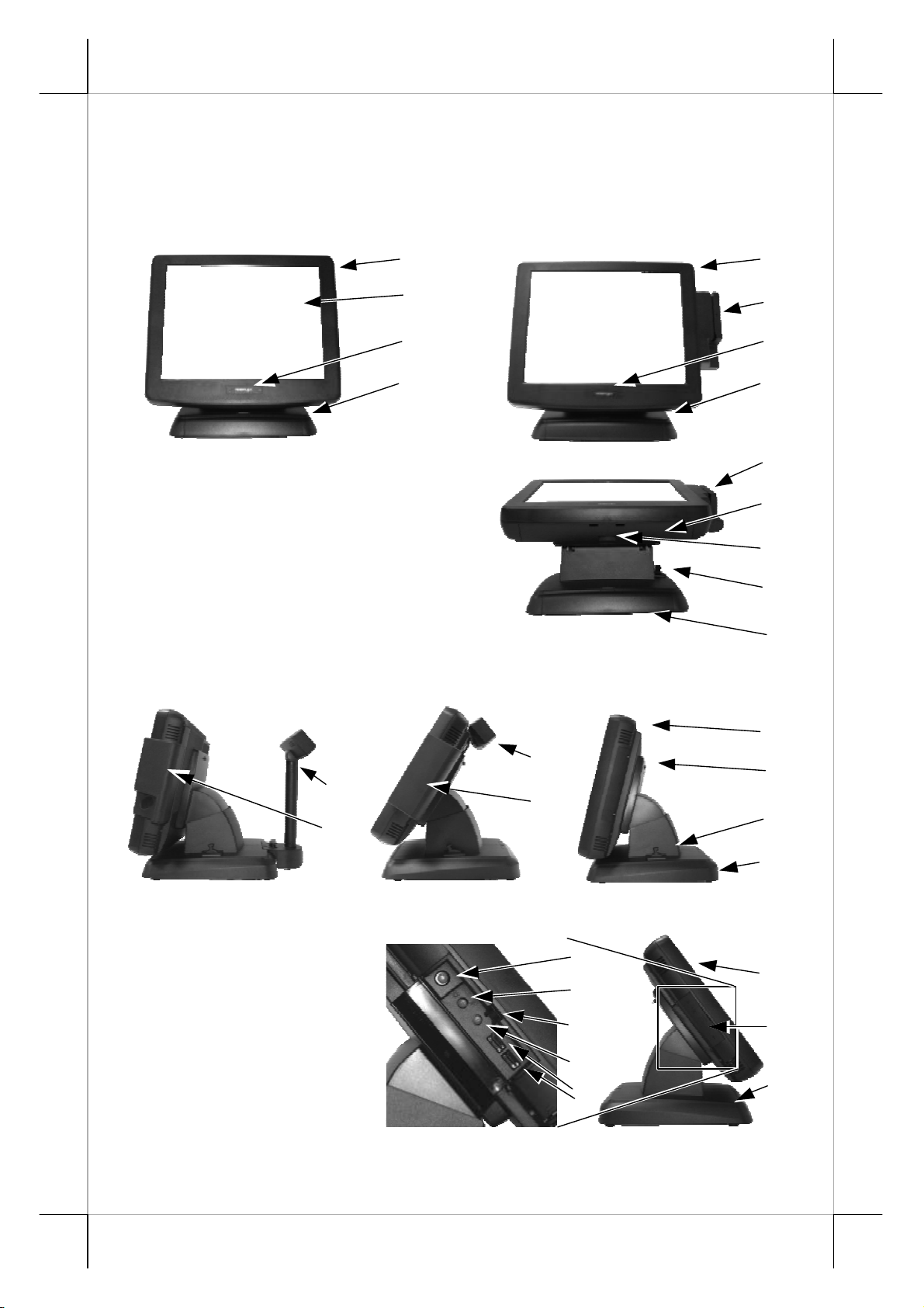
INTRODUCTION
PRODUCT PICTURES
Front Views
1
1
Panel tilted straight
2
3
4
With side mount kit
5
3
4
5
6
7
8
Side Views
Panel tilted back
4
10
5
11
5
Right side view
1
9
8
4
13
14
15
16
17
1
12
4
Left side view Inside touch open door
Part 3
Page 4
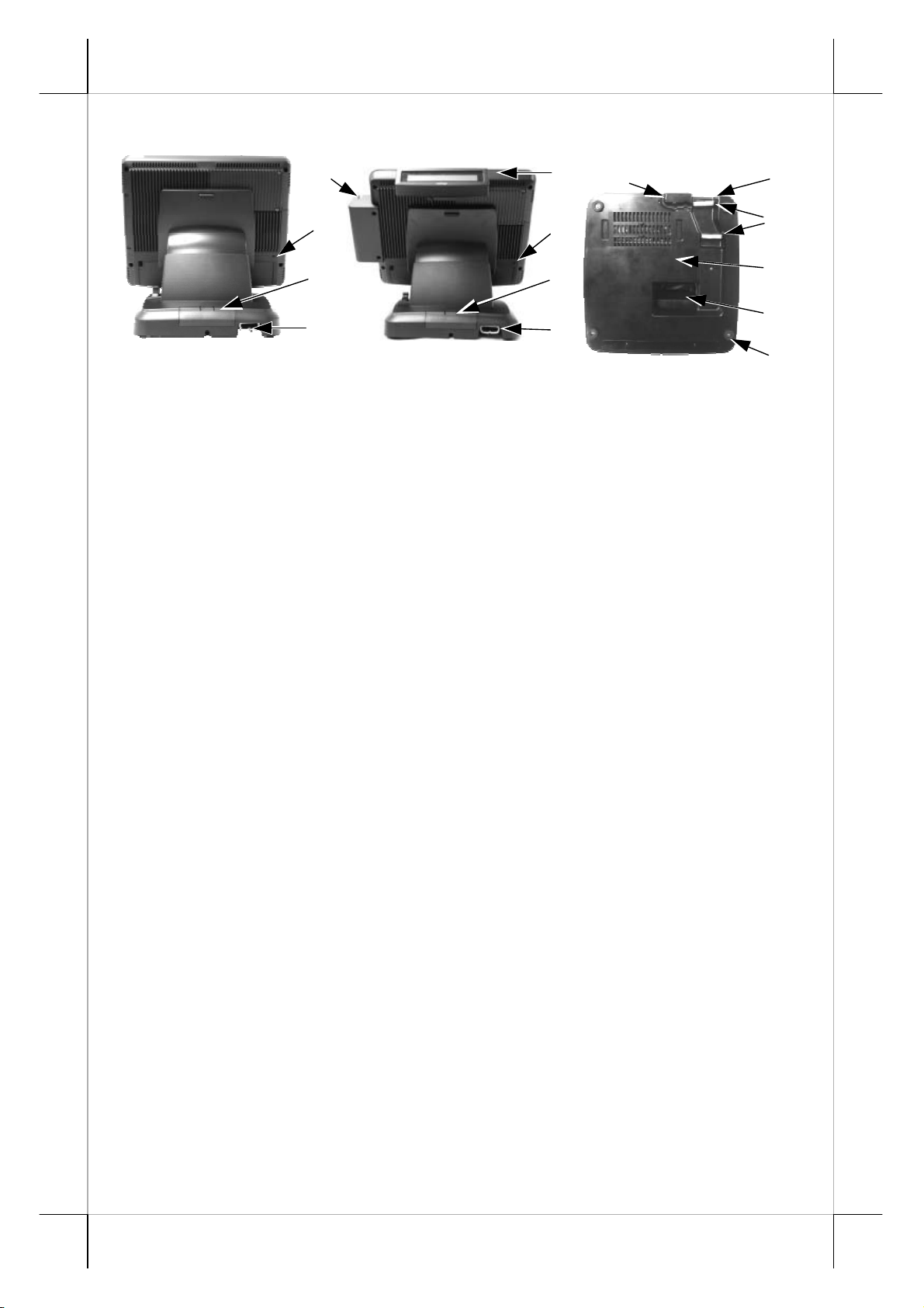
Rear & Bottom Views
5 11
22
20
Rear view w/o
upgrade kit
PARTS IDENTIFICATION
1. Main unit
2. Touch panel / LCD panel
3. Power indicator
4. Gen 5 slim base stand
5. Optional side mount kit e.g. SD-400Z
6. Cable cover
7. Removal hollow in cable cover
8. Lock / release lever for tilt angle adjust
9. Lock / release button for main unit detach
10. Optional base mount kit e.g. PD-2501 or PD-2602
11. Optional rear top mount kit PD-310 or PD-2604
12. Touch open cover
13. Power switch
14. Brightness up button
15. Touch open door latch
16. Brightness down button
17. USB ports in touch open door
18. Kensington security slot
19. Rear connect cover
20. Cable exit
21. Bottom plate
22. Base mount device cable groove
23. Cable holder
24. Cable passage in bottom plate
25. Rubber foot with bottom plate fixing screw
18
19
20
Rear view w/ side &
rear top mount kit
18
19
20
Bottom view
23
21
24
25
Part 4
Page 5

PRODUCT FEATURES
Standard Features:
a) CPU: Intel Atom N270 1.6G FSB533 Cache512K
b) Fan free structure with Aluminum die cast main unit casing for harsh
environment
c) Data storage device: SATA HDD 2.5” 80 GB in main unit or optional
SSD in main unit or optional CF card reader adaptor & CF card in main
unit or optional SATA HDD in base with optional RAID 1 control
d) An advanced slim base design that supports 2
mount customer display on rear base, storage room for optional 2.5”
HDD and optional UPS battery in base. Also possible to be without
base but wall mount bracket for wall mount application.
e) Support WinXP pro, WEPOS, POS Ready and Linux environment
f) High quality 15” TFT active matrix LCD panel
g) Vertical type LCD panel with easy tilt angle adjustment from 15° to
70°
h) LCD brightness adjust buttons at side of main unit
i) Durable resistive type touch panel that endures 35 million touches min.
at same spot (leading edge Infra Red type optional)
j) Spill proof water resistant structure allowing easy cleaning
k) Easy maintenance construction
l) Various I/O ports supported, including:
1. 3 serial ports with 2 in form of DB9 connectors and 1 in form of 10
pin RJ45 type modular connector. The 2 DB9 connectors are
supported with capability for +5V DC support through BIOS setup.
2. 6 standard USB ports with 2 at side and 4 in I/O area below panel
3. two internal proprietary USB ports for touch function and optional
side mount kit (e.g. SD-400Z)
4. one LAN port Ethernet 10/100/1000 Base T with LAN status
indicators on jack (green for link, orange for data transmission)
5. one external VGA monitor port with +12V DC support through
BIOS setup
6. one 22 pin type SATA port for optional SATA HDD in base
7. two LED indicators for storage device operation status
8. one built-in internal 2W speaker
9. one CR port capable of controlling 2 cash drawers max.
10. reserved one LPT interface through use of optional special cable in
service window
11. one 4 pin lock type DC 12 V power input connector
12. one 4 pin connector for optional UPS battery in base
m) Kensington security slot on back cover of main unit to prevent
nd
LCD display or pole
Part 5
Page 6

opportunist theft
n) Touch control functions: left/right button, double click, drag & draw
o) Dual display support (per OS capability)
p) VGA memory size 8 MB shared from system memory supporting
Dynamic video memory technology up to 224 MB
q) Support high performance DDR2 SDRAM with maximum memory
size 2GB in two SODIMM
r) Integrated structure for side mount upgrade kit like SD-400Z with
software programmable MSR parameters for WEPOS or Win XP pro
s) Accidental power off protection – The power switch is safely located
inside a push-open cover and can be set by software to become a “ON
only” switch.
t) Preconditioned power up function – by alarm clock or COM port
MODEM ring or LAN
u) Supports power saving by suspension mode
Option Items:
Note: The underlined items in the following list means that option must be
set prior to shipment from the factory. The rest items can be set by the
dealers.
a) DDR2 SODIMM memory expansion up to 2GB max.
b) RS232 interface Infra-Red type touch panel durable for 50 million
touches min. at same spot
c) CF card reader kit or SSD kit (It can’t coexist with HDD in main unit)
d) Base installed SATA HDD
e) RAID 1 control for both SATA HDD’s in main unit and in base
f) Integrated side mount upgrade kit:
SD400Z: with options MSR, optical fingerprint sensor
KP300: Programmable keypad with options MSR, smart card reader
g) Integrated base mount device choice among: PD2501 or PD2602 VFD
pole display PD306 LCD pole display or 2
nd
LCD panel monitor 12.1”
LM-6101 or 15” LM-6501
h) Integrated rear mount upgrade kit PD-310 LCD customer display or
PD-2604 VFD customer display
i) Preload OS WinXP Pro, WEPOS, POS Ready or Linux
j) Wireless LAN adaptor in USB interface
k) RJ45 to DB9 serial port conversion cable (for COM 3 port) (P/N:
21863233801)
l) Split cable for 2 cash drawer control (Part No. 21863018010)
m) LPT interface conversion cable (P/N: 21862033420)
n) Wall mount kit: WB-6000VB, WB-6300, WB-6600
o) Omni-direction bar code scanner kit SK-200
Part 6
Page 7
INSTALLATION GUIDES
CAUTION: Before any installation or cable connection to the set, please
always make certain that the system is turned off and the
external power source to the set is removed to prevent electric
hazard! Never touch any metal pin in the connectors or
circuits to avoid high voltage hazard or electrostatic discharge
damage unless the operator is well grounded. Failure to do the
above will void the product warranty!
TECHNICAL MANEUVERS
Some technical maneuvers in KS-6815 series such as serial COM port
+5V power supply settings and VGA port +12V power supply setting are
supported in system BIOS setting. However, such support is limited to the
application of specific Posiflex peripherals and must be disabled when the
Posiflex peripherals are disconnected. Failure to follow the discipline would
result in electric or fire hazard and such consequences are not covered by
product warranty! To manipulate each of these functions please select
“Integrated Peripherals” in system BIOS setup and enter “SB GPIO Control”.
The rest applicable technical maneuvers include system CMOS data
reset, system reset, DRAM upgrades, physical access to CF memory card if the
CF card reader option is installed and installation of optional SATA HDD in
base, optional RAID function reset. All these technical maneuver operations
require purchase of applicable Technical Manual from Posiflex or consultation
from Posiflex authorized dealers and should be handled only by a qualified
technician.
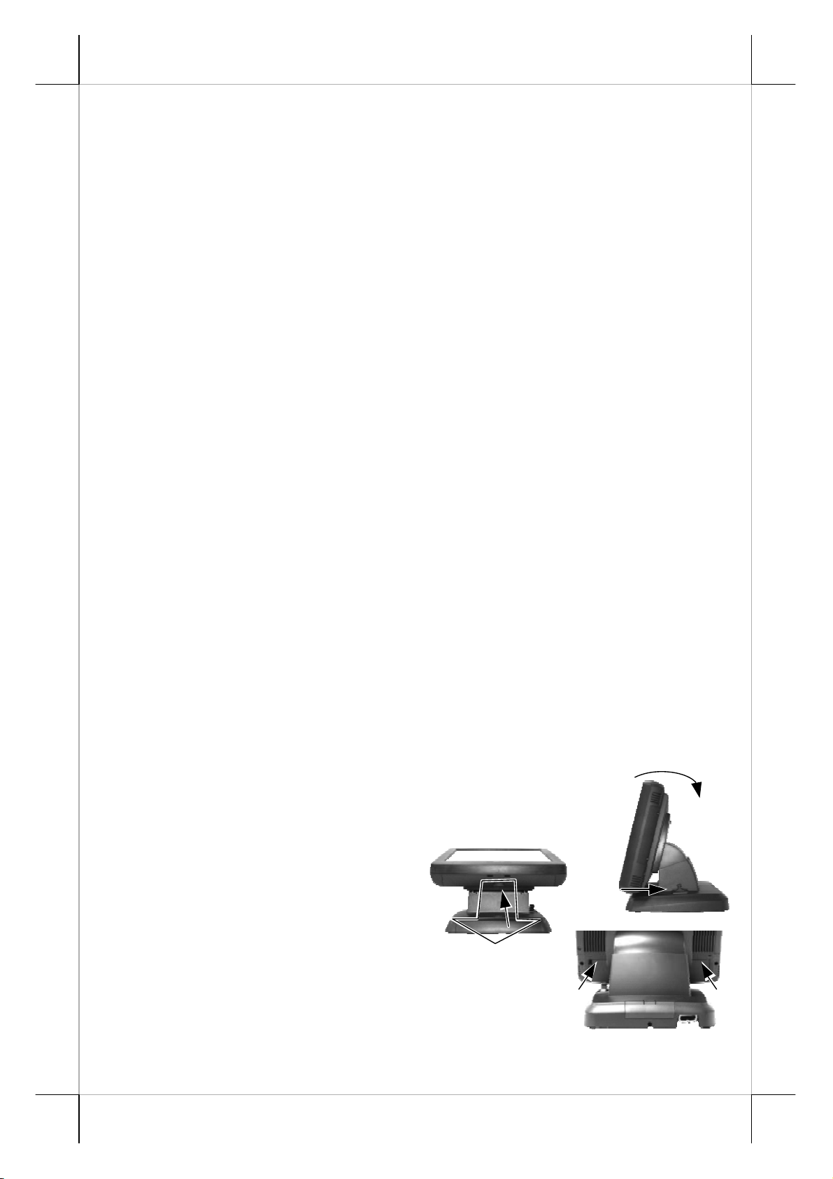
OPENING CABLE COVER
Please follow steps A to C sequentially with reference to pictures
below to remove the cable cover for both slim and universal base models.
Step A: Push lock/release lever for tilt angle adjust
backward
Step B: Turn panel backward to most horizontal position
Step C: Pull at the removal hollow
toward the user
Tips: If there is trouble removing
the cable cover, try pressing
the arrowed portion of cable cover in the rear
view picture at right at the same time.
C
A
Part 7
B
Page 8
DISCONNECTING ALL CABLES
After removal of the cable cover, the connector area will be accessible
then. Please first note orientations of every existing cable connection and
then disconnect every cable properly before separating the main unit from the
adjustable stand assembly. Please note that the click lock spring has to be
pressed down prior to pulling out the connector such as the LAN port or the
CR port or the alternate RJ45 form COM3 port. Please also note that the fixing
screws have to be loosened free prior to disconnection such as the 2 regular
DB9 form COM ports or the VGA port. Please always hold the connector
head instead of pulling on the cable wire when disconnecting any connector.
Failure to do this could damage the cable and jack that is considered as an
artificial destruction. Damages due to incorrect disconnection operation
are not covered by product warranty!
SEPARATING MAIN UNIT
In order to settle the touch terminal properly in a point of sale system,
all the cable connections have to be routed through its base, either slim or
universal. Therefore, please observe the procedures from A to C below to
separate the main unit from the slim base stand assembly after all cables in
cable cover disconnected.
Step A: Prepare a soft clean flat surface, such as
a piece of cloth on the desk to seat the
front surface of main unit
Step B: Press the Lock/Release button for main
unit detach and meantime ...
Step C: Slide the base stand assembly to left to
separate the main unit from base stand
C
B
A
OPENING STAND ASSEMBLY
Take the adjustable stand assembly and
turn it up side down to show the bottom of the
base. Remove the bottom plate fixing screws in
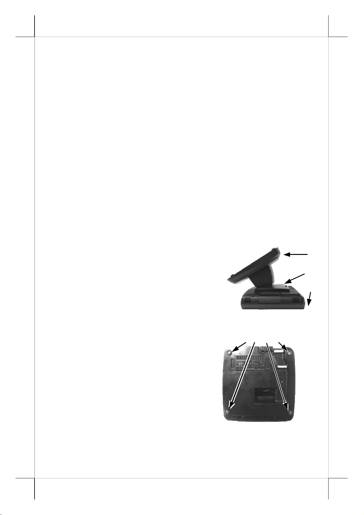
rubber feet to open the bottom plate as in the
picture at the right.
The inside of an example base will look
like the picture below with numbered items
listed. However, there could be some variation
to the contents inside depending on what option
items actually installed.
Fixing Screws
Base bottom
Part 8
Page 9
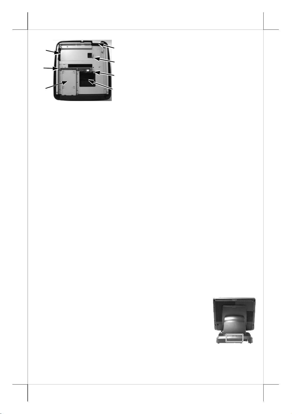
r
5
6
7
Inside base bottom
1
2
3
4
1. Cable Exit
2. UPS Battery Stopper
3. Cable Tie for Option HDD Cables
4. Cable Passage To Main Unit Fo
Desktop Mount Application
5. UPS Battery End Hold
6. Option HDD Conversion Board
7. Option HDD Bracket
INSTALLING UPS BATTERY (OPTION)
When the KS-6815 system is ordered with the UPS battery, the UPS
battery is separately stored in the carton at delivery. Please take the battery out
and place it into the battery compartment by first putting in the end of UPS
battery without cable in the UPS battery end hold of the base and have the end
of UPS battery with cable held against the UPS battery stopper in the base as
indicated in picture above. route the UPS battery cable to reach for main unit
through the cable passage in the base. Apply the bottom plate and screws the
UPS battery will be held in place. Connect the UPS battery to UPS battery
connector of the main unit only when the system is about to power up for
operation. Always disconnect the UPS battery when the system is to be left
powered off for more than few days. Please pay particular attention to the
environment requirement for UPS battery in next chapter “USING THE
TOUCH TERMINAL”.
CABLE PASSAGE FROM BOTTOM
Please route all cables through the cable passage to main unit in
desktop mount application. Hold them together with a cable tie. Pass all cables
other than those for optional HDD kit in base or optional UPS battery through
the cable exit to external connections.
BASE MOUNT UPGRADE KIT
On rear edge of the stand assembly for desktop
mount application, there is a rear connect cover. Either a 2nd
LCD display panel option LM-6101 or a LCD or VFD
customer display option such as PD-305 or PD-306 or PD2501 or PD-2602 can be installed here after removing this
cover. The rear connect cover can be removed easily by
pushing the plastic hook plate at center of it from top side.
Part 9
Page 10
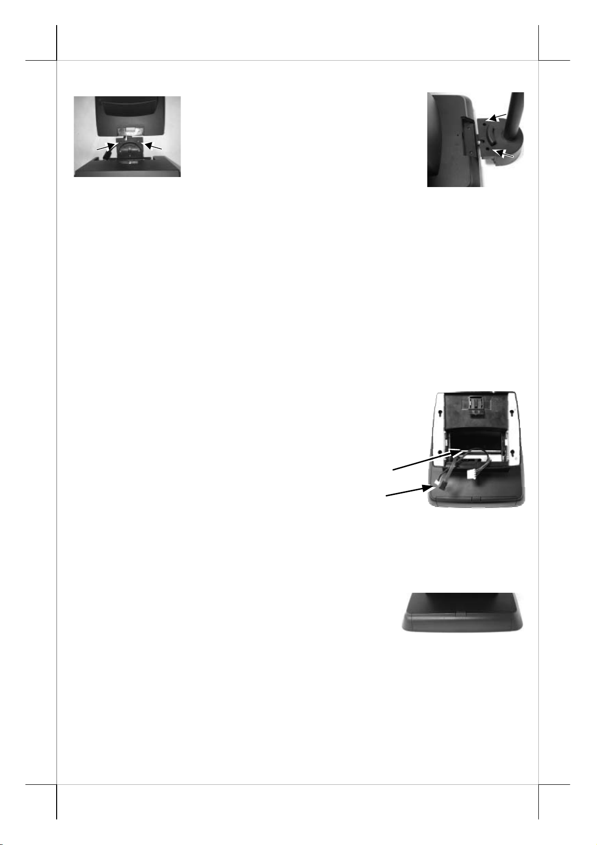
12” 2nd LCD Panel Or Customer Display
Fit the joint base of PD-306
or PD-2501 or PD-2602 or LM-6101
to the rear connect cover opening.
Please route the interface cable
through the normal cable exit (under
the joint base) as in the 2 pictures. Fit
2 screws through washers at the arrowed screw holes to hold the joint tight.
For low profile customer display PD-305, the installation procedure is same.
Remember to enable the +5 V DC supply in the COM port of the main unit for
PD-2501, PD-2602 or PD-305 or PD-306 or the +12 V DC in VGA port for
LM-6101. The power supply in the I/O port must be disabled if it is no longer
required to support these intended devices otherwise any damage or loss
caused consequently shall be out of product warranty! However, if the
customer display used is the USB interface model, the DC supply in COM port
is not required, it will be powered through the USB port. Fit the interface cable
into the base mount device cable groove under bottom plate.
ROUTING THE CABLES THROUGH BASE
Place all the cables required for connections to the
main unit except those for the integrated attachment
through the front part inside the base stand assembly. Be
sure not to damage any cable during this operation.
Now, turn the adjustable base stand assembly back to normal
orientation and arrange all cables to come out of the area for mounting main
unit from the bottom edge for ease of later operation.
Route Cables through Front Part
Connect this End to Main Unit
FRONT COVER OF GEN 5 BASE
Please note that the front cover on Gen 5 base
is designed for easy maintenance of the option HDD in
base and is not for end user application. Please leave it
closed.
PREPAR ING THE MAIN UNIT
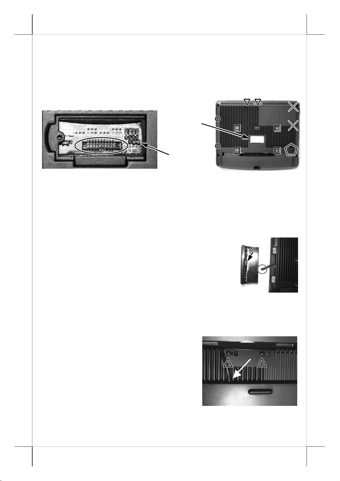
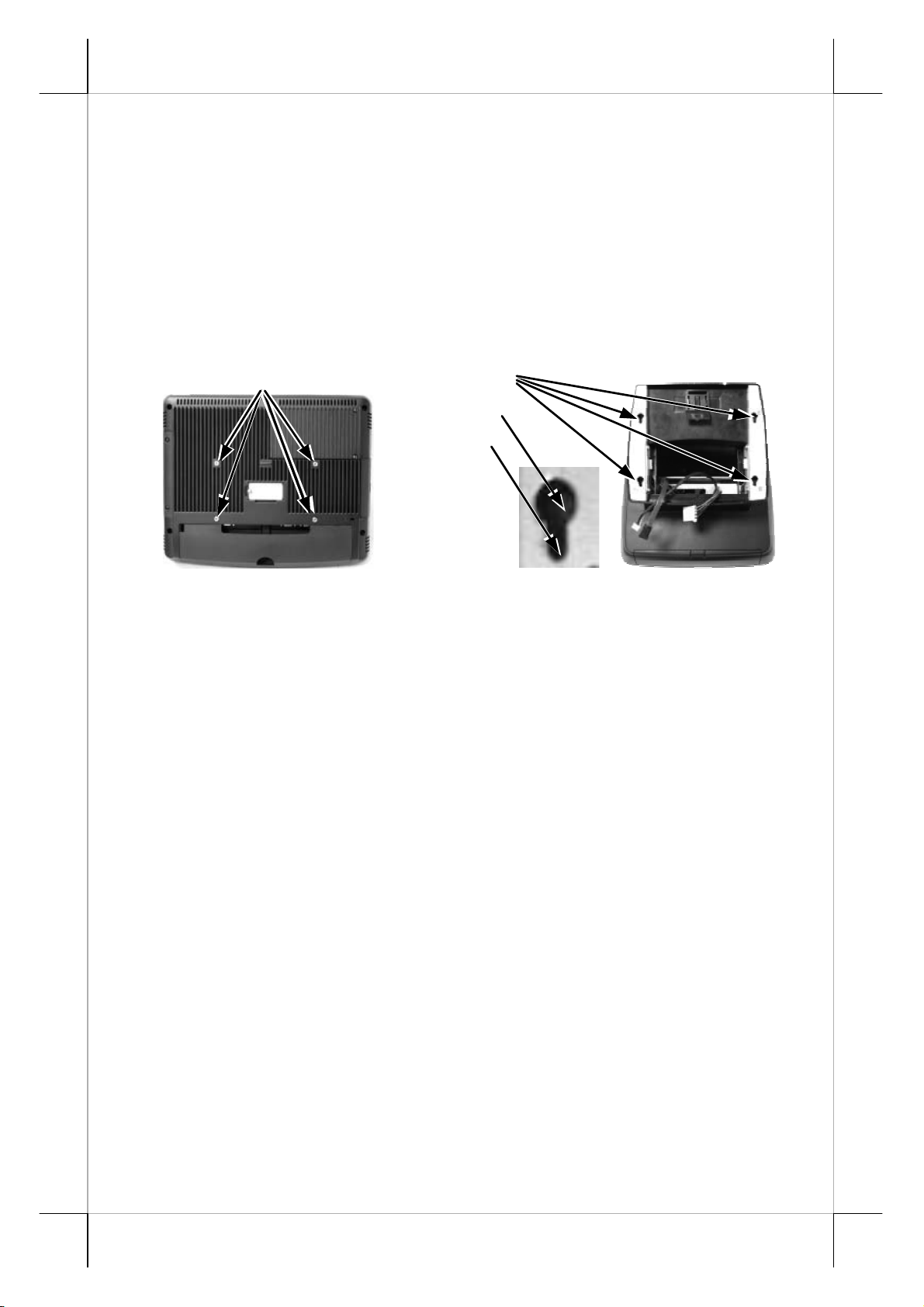
On the back of the main unit, there is a service window among the 4
matching pegs marked in square below. Remove the service window lock
screw to find several jumpers. The jumpers in this window are designated for
hardware reset functions and a reserved LPT port. Please consult your dealer
Part 10
Page 11
w
for technical support on setup of these jumpers. Please note that only those
qualified technicians may adjust in the service window with information from
Posiflex and the contents in the service window may change without notice as
time develops. The option LPT conversion cable should be applied to the
connector as marked in an ellipse in left picture below. Route the conversion
cable from bottom side of the service window plate to connect the usual cable
for parallel device.
Please note the 2 crosses on upper right of the back cover that
indicates the 2 screws holding the cover of HDD cavity where the DDR2
SODIMM and the default SATA HDD or the option SSD or option CF card
reader are sited. Please leave them alone since they are only for qualified
service person to handle.
Service Window
Lock Scre
Jumpers
SIDE MOUN T UPGRADE KIT
Remove the 2 circled screws in last picture above
to remove the cover for side mount upgrade kit. Take out
the cable inside this cover as circled in right picture and
connect it to connector inside the side mount upgrade kit
like SD400Z as arrowed in same picture. Gently arrange
the excessive length of this cable back in the hole and
screw-fit it back to the position originally occupied by the
cover. Please reserve the cover if there is chance to have the side mount kit
removed in the future.
REAR TOP MOUNT UPGRADE KIT
Please apply carefully the 2 small
fixation shoulder screws that come along with
PD-310 or PD-2604 to the back of KS-6815 at
the screw hole triangle marked in the 2 upper
right pictures. However please do not screw
them to the bottom but at a position that is
about 1 turn loose from the bottom. Similarly
please loosen the screws by 1 turn for some
KS models with these 2 screws preinstalled. Hook the rear bracket of the
upgrade kit onto the shoulder screws with the large circular holes. Slide to the
Part 11
Page 12

right the upgrade kit and gently tighten the shoulder screws. Do not overdo
the tightening or unrecoverable thread damage will occur. Arrange the
interface cable to enter the base stand at a notch on the edge near the
lock/release button as indicated by white arrow in above picture. Remember to
enable the +5 V DC supply in the COM port of the main unit for the upgrade
kit if the serial interface model is used. The power supply in the I/O port must
be disabled if it is no longer to support these intended devices otherwise any
damage or loss caused consequently shall be out of product warranty!
However, if the customer display used is the USB interface model, the DC
supply in COM port is not required, it will be powered through the USB port.
CONNECTING CASH DRAWER (OPTION)
The RJ11 connector in I/O area of a KS-6815 system can be used for
controlling most of the common cash drawers available on the market.
However, it is most recommended to use Posiflex CR-2000 or CR-2200 or
CR-3100 or CR-3200 or CR-4000 or CR-4100 or CR-4210 or CR-6310 for
best compliance to operate the opening mechanism and to monitor the drawer
open status.
Use the cable supplied with the cash drawer (Part No. 21863018010)
for connection to the CR port in KS system. This cable has a 6-pole plug at one
end and an 8-pole plug at the other. The 8-pole plug should be inserted into the
connector marked: “signal cable from POS Printer” at the rear of the cash
drawer. The 6-pole plug should be inserted in the connector marked “CR”
found in the main connection area in the system.
The user may also purchase the optional 2-in-1 cash drawer control
cable (Part No. 21863023800) to control 2 cash drawers in 1 port. It has a 6pole plug at one end and two 8-pole plugs at the other. The 6-pole plug should
be inserted in the connector marked “CR” found in the I/O area in the system.
Each 8-pole plug should be inserted into the connector marked “signal cable
from POS Printer” at the rear of one of the cash drawers.
CONNECTING CABLES
To have the re-assembled main unit with stand assembly ready for
operation, please connect all required cables to the appropriate connectors.
Please make sure that each connector is connected to the correct port with the
correct orientation. Damages due to incorrect connection or orientation are
not covered by product warranty!
Some connectors like the COM3 or LAN or CR connector have to be
gently inserted until a click is heard. It is recommended that connectors such as
the COM1/2 and VGA connector be screwed into place once seated.
Adjust the slack of each cable. Re-adjust the tilt angle of the screen
for best viewing.
Part 12
Page 13
Connect the cables to appropriate external devices through the cable
exit at the bottom of stand assembly. Please make sure that each connector has
to be connected to the right device in the right way.
CAUTION: On doing any insertion or extraction of any connector, please
always hold the connector head itself instead of pulling on the
cable wire. Failure to do this could damage the cable and jack
that is considered as an artificial destruction and is not
covered by the warranty.
DESKTOP MOUNTINGKS6115:258~355
Matching Pegs
Match the matchi ng pegs on the back of the main unit against the
matching holes on the base stand assembly. First aim the matching pegs
toward the upper round part of the hole and make sure that all pegs are inside
the holes. Then slide the main unit down to move the pegs into the lower slot
part of the holes till it clicks. Note that all the cables come out of the stand
from the lower edge and won’ t get trapped by this mounting operation. If later
on you want to remove the main unit from the stand, you’ ll have to press down
the lock/release button on back of the stand at the time lifting the main unit.
For desk top/counter application, the total dimension of KS-6815
occupies a space of 378 mm wide, 313 to 316 mm deep and 268 to 362 mm
high per main unit tilt angle.
Matching Holes
Round Part
Slot Part
WALL MOUNTING
The wall mount model is delivered without any base but with a wall
mount kit. Please follow the installation guide that comes with the wall mount
bracket to fix the wall mount bracket on wall and then hang the main unit with
the matching pegs into the matching holes on wall mount bracket.
Please note that since there is no base for the wall mount model there
can be no base installed device nor base mount kit. The area required for wall
mount application is determined by the main unit dimensions and is 378 mm in
width and 312 mm in height.
Part 13
Page 14

UPGRADE WALL MOUNT KIT
There is an upgrade wall mount kit coded as SK-200 that supports an
omni-directional Laser bar code scanner as a derivation from the basic wall
mount bracket WB-6000VB. With this kit, the Laser scanner is installed under
the KS system. Please follow the instructions that come with this kit to install
and to utilize it.
OPERATING SYSTEM RECOVERY
For KS systems with operating system in the CF card if the system is
installed with the CF card reader, once the CF card is damaged, a bootable
new CF card will be required to have the workstation back to work. Please
follow instructions given by the System Integrator to deal with such situations.
For KS systems preloaded with Windows XP Pro / WEPOS / POS Ready
on HDD, Posiflex provides recovery DVD delivered with the touch terminal
for the preloaded operating system. The System Integrator shall take care of
software restoration after OS recovered. A Posiflex supplied USB interface
COMBO drive will be required for such action. Other brand CDROM drive
may require its own driver different from what supported in the recovery DVD.
Please use the recovery DVD in rescue operation only. Using it
otherwise may wipe out whatever stored in the HDD! All upgrade devices
drivers needed for manual installation in usual way are available in the
subfolder “\drivers” in OS recovered HDD and the latest versions of these
required drivers will be available on our web: http://www.posiflex.com.tw
Then follow instructions from your system integrator for software recovery.
.
OPERATING SYSTEM INSTALLATION
This product is a highly professionalized equipment. The installation
of an OS into a machine without any preloaded OS could be a major difficulty
for average user or obstacle by possibly unintentional negligence even for PC
veterans to accomplish such a task. Therefore, OS installation into a system
without preloaded OS is highly discouraged. Posiflex Technologies, Inc. shall
not be responsible for any technical support to questions on this aspect.
15” 2
A bracket kit including a steel interface bracket
will be provided with the 15” 2
Please follow the accompanying installation guide to mount
the interface bracket and fix it to the rear connect area of the
system as in the right picture. Route the VGA cable through
the cable exit of the base stand to the main unit. Fit the VGA cable into the
base mount device cable groove under bottom plate of Gen 5 base. Connect the
attached power adaptor for its power source.
nd
LCD Panel
nd
LCD panel LM-6501.
Part 14
Page 15

USING THE TOUCH TERMINAL
APPLICATION ENVIRONMENT
It is very important that you check the following operational
guidelines:
Ventilation
This terminal must NOT be operated in an environment with
restricted ventilation. There must be at least 25 mm air clearance around any
top or side ventilation holes with a free flow of air around the unit at ALL
times for the installation.
Operating Environment
The equipment must not be operated or stored in extremes of both
temperature and humidity/moisture. (Operating range 0°C to 40°C and up to
80% humidity – non condensing, max. wet bulb 26C)
UPS Battery (option)
General care:
The UPS battery is consumables beyond product warranty. Please
definitely observe the alerts in beginning of this manual. If the equipment is to
be powered off for more than few days, please always disconnect the battery
from the system. Reconnect it and turn on the system to recharge the battery
for 1 ~ 2 hours every 3 months for temperature lower than 30C. Recharge for
1 ~ 2 hours every month for temperature over 30C. Temperature above 40° C
must be strictly avoided as it could cause termination of battery life and
unexpected result even if the battery is not in work. The UPS battery can
support basically the data preservation and smooth running of the system
during intermittent or few minutes (30 min. up depending on loading and
battery condition) power failure.
Battery replacement:
When the UPS battery is installed, the user can install the utility
Power Manager that will interface the UPS battery monitor status with user.
Find “PSW_vxxx” in the folder \drivers of the
preloaded OS or search in the product information
CD to install it. Please replace the used up UPS
battery at power off whenever the message at the
right appears.
Emergency treatment:
The battery is constructed maintenance free and leakproof. It is well
protected in KS system as long as the ambient temperature remains below
30C and the ventilation of the KS system remains free. However, should any
accident happen and the sulfuric acid from the battery spills on skin or clothing,
Part 15
Page 16
wash immediately with water. If the acid comes in contact with eyes, rinse
eyes with large amount of clean water and see a doctor immediately. A larger
external battery may be connected to give an extended operation. Please check
your dealer about this capability when required.
WARNING:
If there are any signs of over charging or leakage of electrolyte
please contact your dealer immediately
Power Supply
The operating voltage range of the power adaptor should cover the
local power supply for proper operation. The power cable, the power outlet
and any power fusing arrangements must conform to local safety regulations.
Please never do any connection / disconnection when system is still
powered on. Please always keep the external power adaptor in a free air
circulation.
POWER ON/OFF
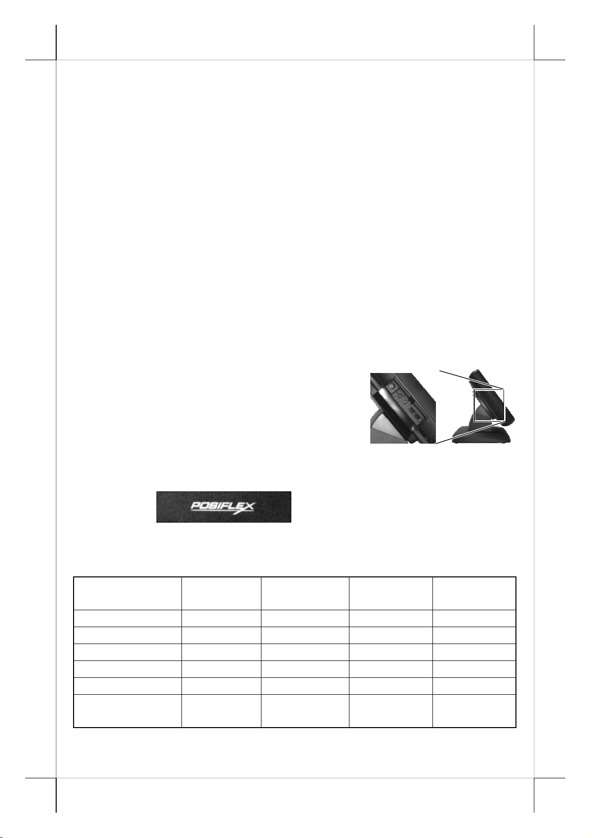
Touch Open Cover
A gentle tap on the touch open cover at
left side of the main unit will open the cover and
show the power switch at top area. It is preferable
to keep this door closed through daily operation.
There must always be at least 10 seconds
waiting before switching on again once the system is powered off successfully.
Power Indicator
There is a power indicator LED module serving for several purposes
under the logo at center of lower rim of LCD panel. The relationship between
the indicator status and other conditions is summarized in following table:
Indicator Status
System
Status
Off Off Off Not present Not possible
Off Off Off Present Not allowed
Green Off On No influence Allowed
Blue On On No influence Not required
Blue/flash On Off Activated Not required
Green/rapid flash On Off
External
UPS Battery Powering Up
Power
Running at
Not required
low capacity
Part 16
Page 17

Hardware Power Switch
The power switch located in the touch open cover of the main unit is a
tactile pushbutton switch. This switch controls the power on/off of the system.
This switch turns the system on when pushed only when external power is
present. This switch turns the system off when pushed again during power on
status. However, if the system hangs due to any reason such as software
resource conflict a simple push on the switch may fail to turn off the power. In
this case, please utilize the forced power off feature by pressing the switch
and holding for within 10 seconds. In case the turmoil is so vigorous that some
hardware registers may be confused causing trouble for system restart or even
this forced power off, please disconnect the UPS battery if installed and the
AC power supply for few minutes. This may reset all hardware registers.
This switch can also be programmed as an ON only switch. That
means, if the application program issues a command compliant with the KS
series technical manual, this switch will always turn the system on when
activated, but will not power off the system when pushed again (the forced
power off feature will not work in this mode). When using this feature, please
make sure that the software application has the ability to power off the
machine. In preloaded Windows, “Posiflex Power Switch Manager” in
“Posiflex Tools” in the Program Files helps managing these functions.
Software Support Features
The KS series provides a software power off command for application
program maneuvers. The KS also provides a specific means for the software to
detect if the system is working on external or UPS battery power. Due to this
feature, compatible software applications have the ability to change operating
conditions when running on standard/backup power. The software programmer
may take reference from the KS technical manual to apply such features.
Automatic Power On Control
The system may also turn on according to some preset conditions
such as Modem Ring Up and Alarm Clock Wake Up or LAN Wake Up.
To utilize Modem Ring Up or Alarm Clock Wake Up function, the
user should enter the BIOS setup by pressing “Del” key at system boot up,
choose in “Power Management Setup” and make the “Power On by Ring”
enabled for Modem Ring Up or enable the “Resume by Alarm” for Alarm
Clock Wake Up. Save the configuration and exit the BIOS setup program. The
Preset Power On Control will then be ready. For LAN wakeup, the item “PCI
Express PM Function” must be enabled in “Power Management Setup” and an
operating caller system connected through LAN to the system is required. It
also requires a qualified networking technician to check the LAN chip ID of
the system for the caller system to wake up.
Part 17
Page 18
When the KS system is turned off after a successful boot up, the
preset automatic power on functions will keep monitoring for the preset
conditions and turn on the system when the preset conditions are met.
Please note that if the KS system is improperly turned off before a
complete boot up procedure, the above preset power on control functions will
be disabled until next turning off after a complete boot up.
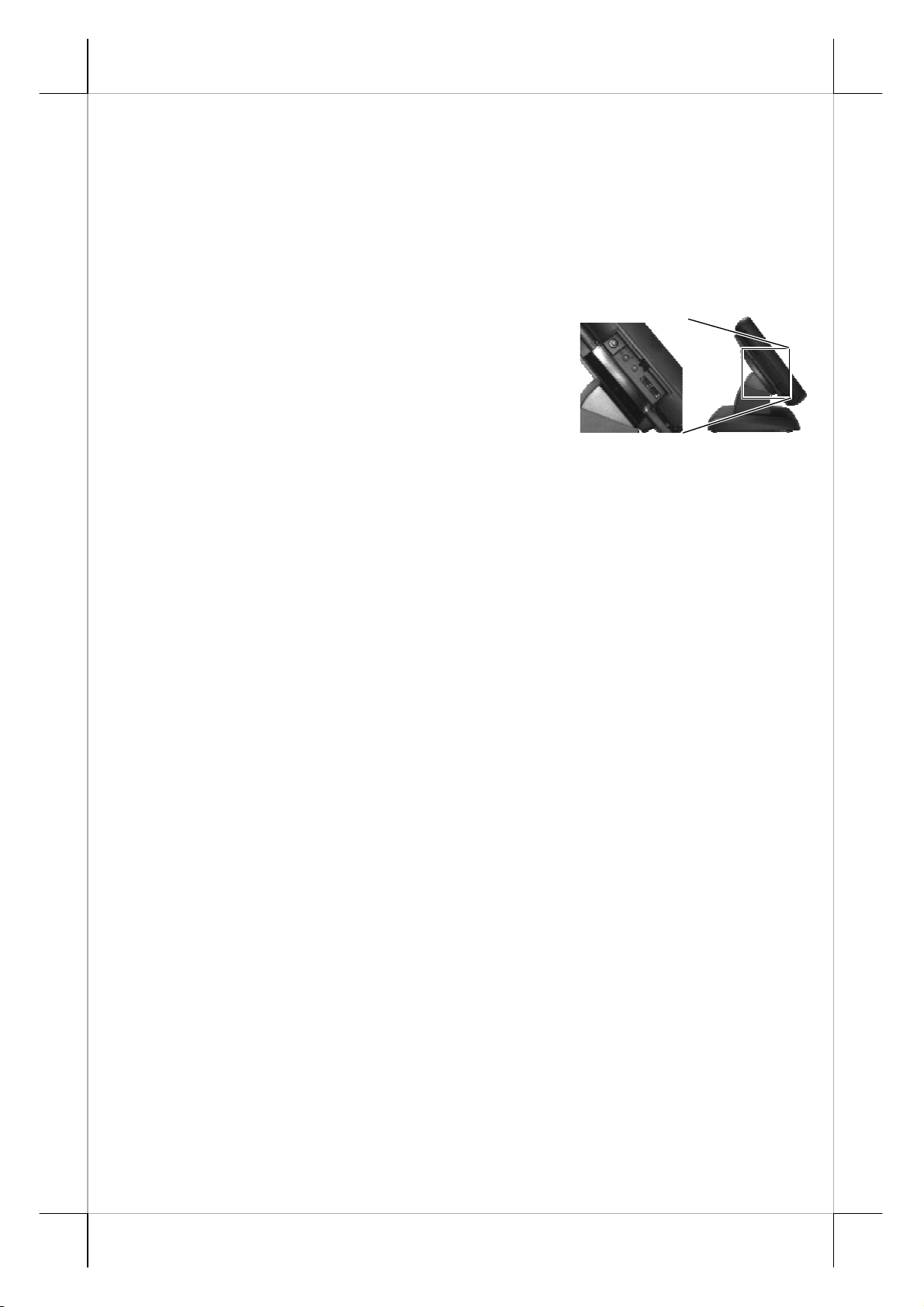
BRIGHTNESS CONTROL
At left side of the main unit below the
power switch, there are brightness adjust push
button switches and two USB connectors. Each
single press on the + or – button changes the LCD
panel display brightness by a small amount. When
you press and hold the button the change will keep on until release or extreme
condition matched.
USB PORTS
There are in total 6 USB ports for external connection: 2 at left side
below power switch and LCD brightness adjust buttons; 4 in I/O area. All of
them comply to USB 2.0 standard.
DISPLAY ISSUES
Main LCD Display
For best viewing result please set your display resolution at 1024 x
768 with high color.
The system Video Memory is shared from system memory. The video
memory size is default 8 MB and can support DVMT up to 224 MB.
VGA Port
The VGA port in the KS-6815 system supports either a base mount
nd
2
display or a separately connected LCD monitor or touch monitor. To
support the DC power to the 2
to set the power supply in KS main unit through the VGA connector according
to Posiflex technical information. Do not connect other monitor to this port
before the power in this port is disabled.
Note: When 2
nd
boot up stage and application in some OS will be smaller than usual in both 1
and 2
nd
displays.
nd
display LM-6101, have a qualified technician
display is connected, the screen display of system
st
CUSTOMER DISPLAY
Please follow the instructions on the manual that comes along with
the customer display PD-2501 or PD-2602 or PD-305 or PD-306 if installed.
Part 18
Page 19
SERIAL PORTS – COM1/2/3
In KS-6815 system, there are 2 serial ports in form of DB 9 pin male
connectors and 1 in form of 10 pin RJ45 type modular connector available.
Both DB 9serial ports can supply a +5 V DC through pin 9 after proper BIOS
setup. However, do not connect any other device to this port before the
power in this port is disabled.
When a serial Modem is to be used in KS system, it is most
recommended to use COM3 port with a conversion cable unless a special
internal setting has been made on COM3.
STORAGE DEVICES
The standard system storage device is a 2.5” SATA HDD in the main
unit. This device can be replaced with an option SSD or an option CF memory
card reader. There is also an option to have SATA HDD in the base and
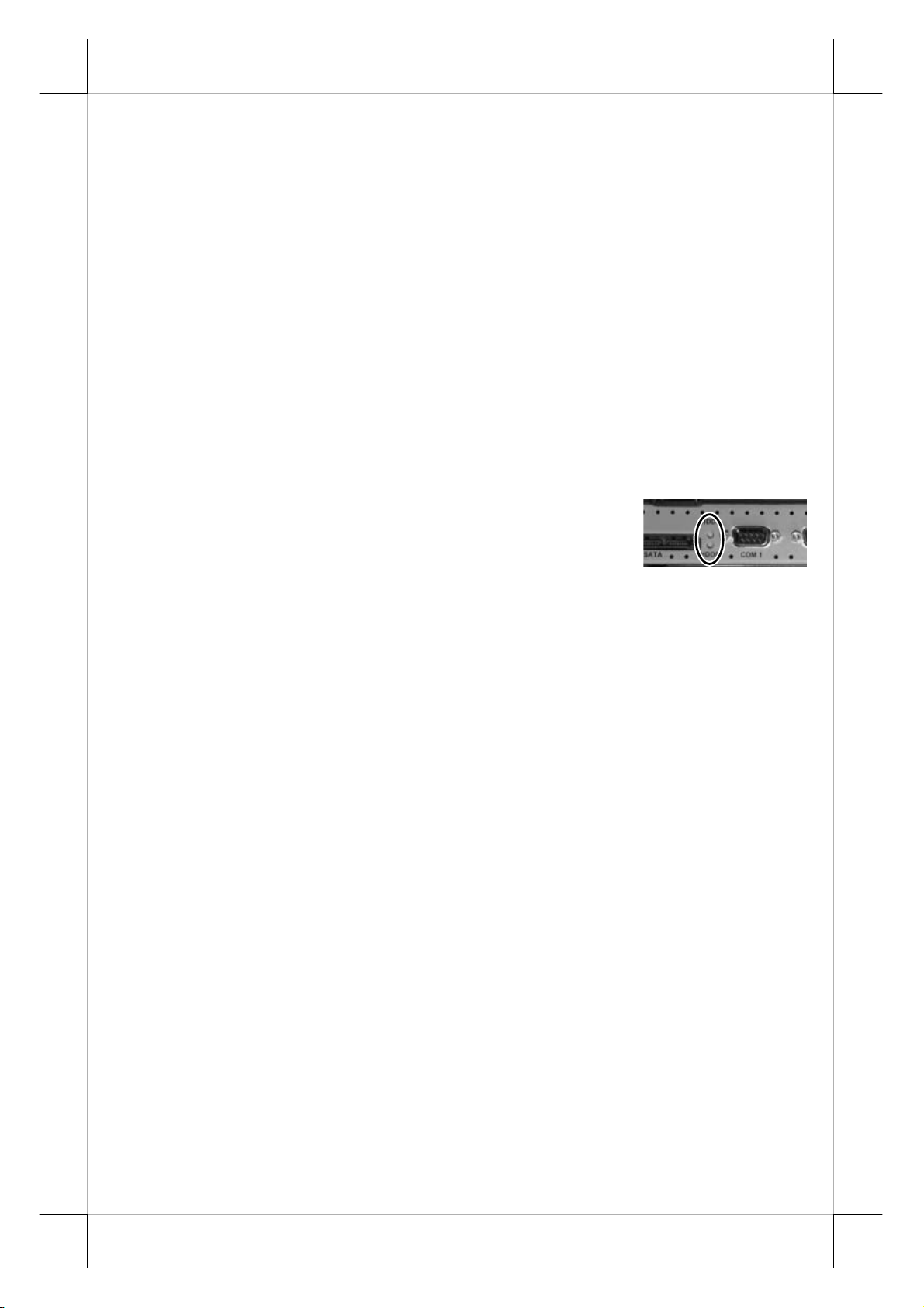
another option to have also a RAID control. In the system I/O area between the
COM1 connector and the SATA port there are 2 LED’s
as marked in the right picture to indicate the operation
status of the HDD’s. When the RAID function is engaged,
the lower LED (marked HDD0) indicates the status of the primary HDD (the
one in main unit) and the upper LED (marked HDD1) indicates the secondary
HDD (the one in base). When there is no RAID function, the lower LED
(HDD0) indicates status of either HDD and the upper LED (HDD1) indicates
the status of optional CF card.
PARALLE L PO RT
In KS-6815 system, the parallel port can be available only through
use of the optional conversion cable. It should be connected to the special
connector inside the service window as described earlier. The other end of the
cable is the normal 25 pin D sub female LPT connector.
TOUCH PANEL
All paragraphs below are applicable for models with touch panel only.
The user of those models without touch panel can ignore them and consider
this user’s manual ends here.
Mouse Emulation
The touch panel in KS-6815 system uses internal USB interface as
standard and occupies no external port. Only the optional InfraRed type touch
panel of KS-6815 uses RS232 interface and occupies an internal COM4 port.
When the touch driver is properly installed, this touch panel works exactly like
a standard mouse for each interface. However, if the system is running under
safe mode, the touch panel calibration may become unsatisfactory due to
Part 19
Page 20

disabled drivers. It is recommended to use a standard USB mouse or keyboard
in this mode.
All the below mentioned mouse emulation functions can be
manipulated through relevant software. The system can give a beep and a click
on the left button of a mouse at the point when the touch panel is touched. If
the point touched is dragged across the screen surface, it works as the mouse
drag and drop feature. If the point is touched, released and touched within a
short time interval, it is double-clicking left button of the mouse. To obtain the
effect like clicking on the right button of a mouse, touching any point on the
screen surface after touching the right-click sticky button results as a click on
the right button of the mouse at that point.
Posiflex USB Touch Manager
A program named “Posiflex USB Touch Manager” and a right-click
sticky button tool in the program group “Posiflex USB Touch Tools” is
installed in the preloaded Windows system with a USB interface touch panel
controller. This program can also be obtained by download from the
POSIFLEX web site.
RS232 Touch Cont r oller
If the KS system purchased is the leading edge Infra Red type touch
models, the touch controller is of RS232 interface using an internally reserved
COM4 port. The “Posiflex USB Touch Manager” above should be disregarded.
Once the RS232 touch controller driver is installed, the user can
utilize it to control the mouse emulation. Please click “Start”, “Settings”
“Control Panel” and “Elo Touchscreen” or just click the “elo” icon in tool tray
to engage this utility. However, with this touch controller driver, certain
display mode like full screen display of Windows DOS box should be avoided.
Part 20
T31454
ᙆѓ
本電池如果更換不正確會有爆炸的危險
請依製造商說明書處理用過之電池
ᙆѓԴ٫
這是甲類的資訊產品,在居住的環
境中使用時 ,可能會造成射頻干
擾,在這種情況下,使用者會被要
求採取某些適當的對策 。
 Loading...