

KB6000 SERIES
102 - KEY & QWERTY
PROGRAMMABLE KEYBOARD
USER’S MANUAL
Rev. : Original

SOME IMPORTANT NOTES
FCC NOTES
and used in accordance with the instructions manual, may cause interference to radio communications. It
has been tested and found to comply with limits for a Class A digital device pursuant to subpart J of Part
15 of FCC Rules, which are designed to provide reasonable protection against interference when
operated in a commercial environment. Operation of this equipment in a residential area is likely to cause
interference in which case the user at his own expense will be required to take whatever measures to
correct the interference.
WARRANTY LIMITS
the authorized technicians. The user should consult his/her dealer for the problem happened. Warranty
voids if the user does not follow the instructions in application of this merchandise. The manufacturer is
by no means responsible for any damage or hazard caused by improper application.
ABOUT THIS MANUAL
powerful programmable keyboard KB-6000 series which is constructed of a 6 by 17 matrix of press keys
which provides excellent tactile click when pressed. The KB-6000 series not only is capable of being
programmed to transmit whatever code a standard PS2 keyboard can deliver, but also provides a great
variety of programmability such that contains all capabilities of the most modern programmable
keyboards.
change or to modify this manual without notice due to the rapid and constant progress and improvement
on science and technology.
All rights are strictly reserved. No part of this documentation may be reproduced, stored in a retrieval
system, or transmitted in any form or by any means, electronic, mechanical, photocopying, or otherwise,
without the prior written consent of Mustek Corp. the publisher of this documentation.
TRADE MARKS AND SERVICE MARKS
of their respective owners.
This equipment generates, uses, and can radiate radio frequency energy and, if not installed
Warranty will terminate automatically when the machine is opened by any person other than
This manual is written in an attempt with full strength to assist the user to utilize the
The manufacturer of this product heartily apologizes to the user for reserving the right to
© Copyright Mustek Corp. 2002
POSIFLEX is a registered trademark of Mustek Corp..
Other brand and product names are trademarks and registered trademarks and service marks
P/N: 19160900010

TABLE OF CONTENTS
OVERVIEW . . . . . . . . . . . . . . . . . . . . . . . . . . . . . . . . . . . . . . . 1 - 1
SCOPE . . . . . . . . . . . . . . . . . . . . . . . . . . . . . . . . . . . . . . . 1 - 1
FEATURES . . . . . . . . . . . . . . . . . . . . . . . . . . . . . . . . . . . 1 - 1
MODEL NUMBERS & LAYOUTS . . . . . . . . . . . . . . . . . 1 - 2
KB6000 . . . . . . . . . . . . . . . . . . . . . . . . . . . . . . . . . . 1 - 2
KB6200FR . . . . . . . . . . . . . . . . . . . . . . . . . . . . . . . . 1 - 2
KB6200GR . . . . . . . . . . . . . . . . . . . . . . . . . . . . . . . . 1 - 3
KB6200IT . . . . . . . . . . . . . . . . . . . . . . . . . . . . . . . . 1 - 3
KB6200JP . . . . . . . . . . . . . . . . . . . . . . . . . . . . . . . . 1 - 3
KB6200NL . . . . . . . . . . . . . . . . . . . . . . . . . . . . . . . . 1 - 4
KB6200PO . . . . . . . . . . . . . . . . . . . . . . . . . . . . . . . . 1 - 4
KB6200SP . . . . . . . . . . . . . . . . . . . . . . . . . . . . . . . . 1 - 4
KB6200SV . . . . . . . . . . . . . . . . . . . . . . . . . . . . . . . . 1 - 5
KB6200TW . . . . . . . . . . . . . . . . . . . . . . . . . . . . . . . . 1 - 5
KB6200UK . . . . . . . . . . . . . . . . . . . . . . . . . . . . . . . . 1 - 5
KB6200US . . . . . . . . . . . . . . . . . . . . . . . . . . . . . . . . 1 - 6
ACCESSORIES . . . . . . . . . . . . . . . . . . . . . . . . . . . . . . . 1 - 6
OPTIONS . . . . . . . . . . . . . . . . . . . . . . . . . . . . . . . . . . . . . 1 - 6
INSTALLATION . . . . . . . . . . . . . . . . . . . . . . . . . . . . . . . . . . . 2 - 1
CABLE CONNECTION . . . . . . . . . . . . . . . . . . . . . . . . . 2 - 1
INSTALLATION ON TP7000 SERIES . . . . . . . . . . . . . 2 - 1
UTILITY INSTALLATION . . . . . . . . . . . . . . . . . . . . . . . 2 - 1
PROGRAMMING SETUP . . . . . . . . . . . . . . . . . . . . . . . . 2 - 2
PROGRAMMING THE KEYBOARD . . . . . . . . . . . . . . . . 3 - 1
PROGRAMMING UTILITY (KBM.EXE) . . . . . . . . . . . . 3 - 1
QUICK REFERENCE GUIDE . . . . . . . . . . . . . . . . 3 - 1
HARDWARE LIMITATION . . . . . . . . . . . . . . . . . . 3 - 1
PROGRAMMING UTILITY (KBW.EXE) . . . . . . . . . . . 3 - 2
SHORTCUT UTILITY (RWM.EXE) . . . . . . . . . . . . . . . . 3 - 2
APPLICATION . . . . . . . . . . . . . . . . . . . . . . . . . . . . . . . . . . . . 4 - 1
KEYBOARD CONSTRUCTION . . . . . . . . . . . . . . . . . . 4 - 1
i

KEY TOP LABELING . . . . . . . . . . . . . . . . . . . . . . . . . . . 4 - 1
KEY TOP REPLACEMENT . . . . . . . . . . . . . . . . . . . . . . 4 - 2
SPECIFICATIONS . . . . . . . . . . . . . . . . . . . . . . . . . . . . . . . . . 5 - 1
ii

I. OVERVIEW
A. SCOPE
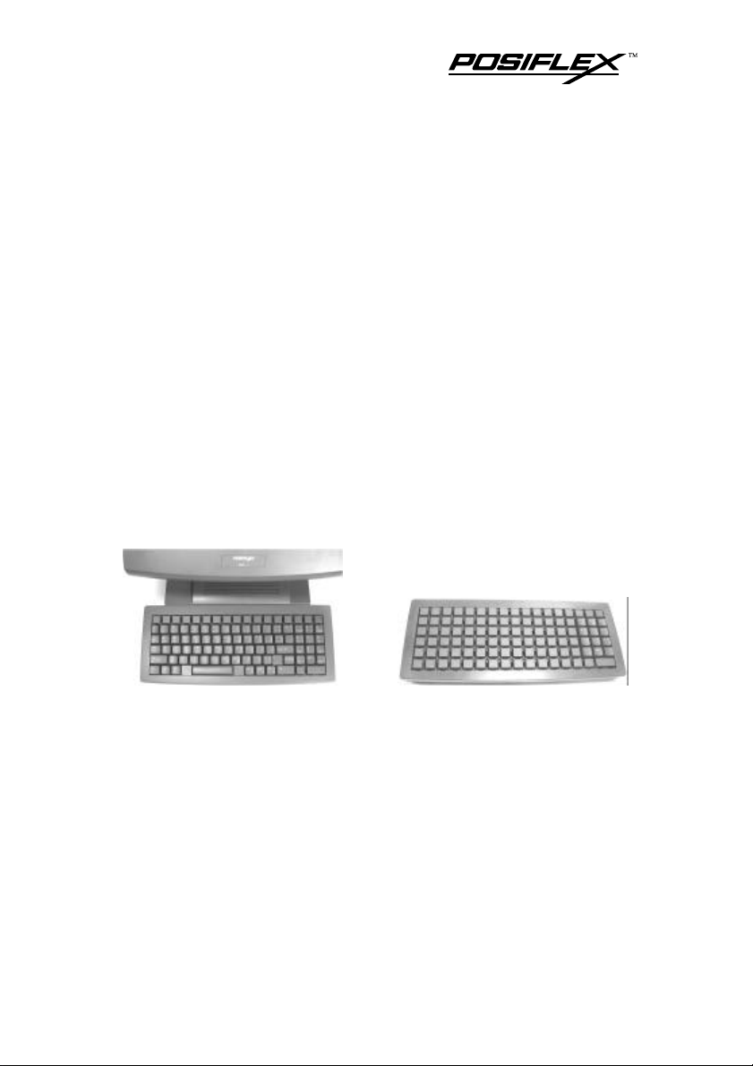
The KB6000 series is a very useful programmable keyboard
suitable for application in PS2 keyboard port of a PC or compatible
system and is particularly recommended for use in a Posiflex touch
terminal such as a TP7000 system. It is programmable under DOS, or
Windows98/NT/2000/XP environment. The KB6000 series is structured
in a 6 by 17 matrix and supports basically 2 types of the key layout. The
model KB6000 provides a numerical keypad in right side of the
keyboard and 1 horizontal double key under it. All the rest parts remain
in form of single keys preserving the flexibility to convert into double
keys or blank keys for best presence in application. The KB6200xx
models provide in the lower part a “QWERTY” keyboard that resembles
the standard PC keyboard and at the top a row of 17 locations for freely
programming purpose. In addition to this, there are 2 more
programmable keys within the “QWERTY” region. The “QWERTY”
region is available for layout of various countries. Should there be any
further question, please visit our web site. (http://www.posiflex.com.tw)
B. FEATURES
l Provide either matrix layout programmable keys with numerical
keypad or QWERTY layout with 19 programmable keys
l Provide powerful programmability (programming under DOS, off-
line programming under DOS, programming under Windows,
multiple level, whole range key content, time delay, etc.)
l Total memory size for keys to be programmed: 8 KB
l Base structure of a 6 by 17 matrix
l 100% true spill-proof construction
l Reliable and pleasant key click
l Extension keyboard connector
l Comfortable key size
l Alternative double key
KB6000 Series User’s Manual 1 - 1
l Wear resistant Laser marked numeric and QWERTY keys
l Transparent key cap for label protection of programmable keys
C. MODEL NUMBERS & LAYOUTS
• KB6000 Basic model, with a numerical keypad
• KB6200xx Qwerty models per language in table below
xx Language xx Language xx Language
FR French NL Netherlands TW Traditional Chinese
GR German PO Portugal UK United Kingdom English
IT Italian SP Spanish US United States English
JP Japanese SV Swedish / Finnish
The key top layout for each model is illustrated below.
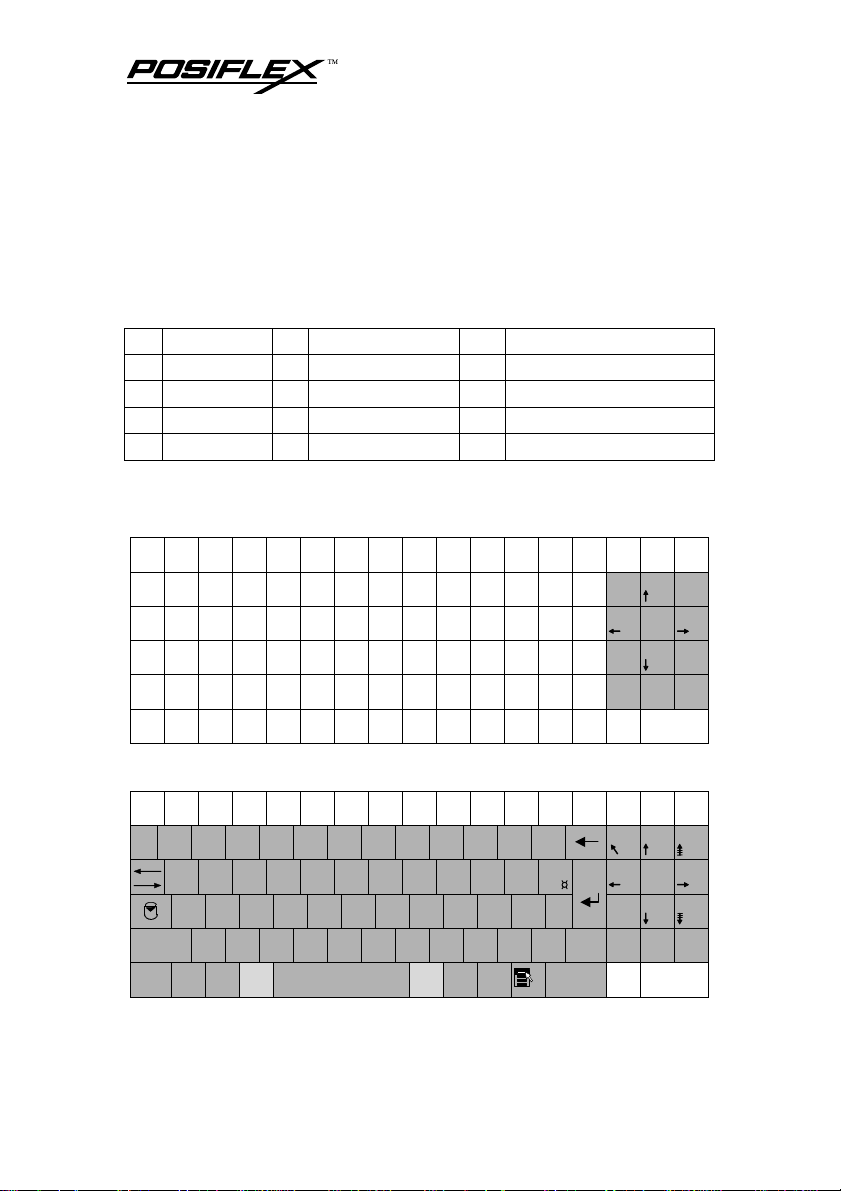
1. KB6000
7
Home
4 5 6
1
End 2 3 PgDn
0
Ins
8 9
00
PgUp
.
Del
2. KB6200FR
2
3
4
5
6
² 1 &
|
|
ñ
Ctrl
" #
' {
é ~
A Z E R T Y U I O P
Q S D F G H J K L M %
W X C V B N ?
Alt
ÿ
( [
7
- ¦
è ` 8 _ \ 9 ç ^ 0 à @
,
.
;
Alt Gr
/ : §
ÿ
°
) ]
¨
^
!
ù
KB6000 Series User’s Manual 1 - 2
+
= }
£
Entré e
$
µ
*
>
ñ
<
Ctrl
7 8 9
4 5 6
1
Fin 2 3
0
00
Inser
.
Suppr

=£
漢字番
3. KB6200GR
!
"
°
1
2 ² § 3 ³ $ 4
^
Q
|
Strg
W E R T Z U I O P Ü *
|
@
A S D F G H J K L Ö Ä '
ò
Y X C V B N M
ñ
Alt
ÿ
%
&
/
5
6
7 {
(
8 [
µ
)
9 ] = 0 }
; , : . _
Alt Gr
ÿ
?
β \
_
`
´
+ ~
#
>
ñ
< ¦
Strg
7
8 9
Pos1
Bild
4 5 6
1
Ende 2 3 Bild
0
Einfg
.
00
Entf
4. KB6200IT
¦
!
"
\
1
2 £ 3 $ 4
Q W E R T Y U I O P é
|
|
A S D F G H J K L ç
Ctrl
Z X C V B N M
ñ
Alt
ÿ
%
&
5
/ 7 ( 8 )
6
9 = 0
ò @
; , : . _
Alt Gr
ÿ
?
'
è [ * + ]
°
à #
_
^
ì
Invio
§
ù
>
ñ
<
Ctrl
7 8 9
Pag
4 5 6
1
Fine 2 3 Pag
0
Ins
.
00
Canc
5. KB6200JP
半角/
!
"
# あ
$ う
% え
& お
' や
( ゆ
) よ
K
も
前候補
換
全候補
9 よ
に
の
< 、
, ね
O
ら
L
カタカナ
ひらがな
ローマ字
~ を
0 わ
P 『
り
> 。
. る
+ 』
; れ
Alt
全角
1 ぬ
2 ふ
3 あ
4 う
5 え
6 お
7 や
漢字
Q
W
E い
R
T
|
Tab
Caps Lock
英
ñ
Ctrl
|
A
| ¬
¥ –
ÿ
た
ち
Z つ
Alt
て
い
S
D
と
し
X
C
さ
つ
無換
Y
す
か
F
G
は
き
V
B
そ
ひ
8 ゆ
U
I
ん
な
H
J
く
ま
N
M
こ
み
KB6000 Series User’s Manual 1 - 3
- ほ
せ
? ・
/ め
`
@ 〝
* ケ
: け
ÿ
¯ 々
7
^ へ
¢
Enter
{ 「
[ º
} 」
] む
_ ¦
ñ
\ ろ
Ctrl
8 9
Home
PgUp
4 5 6
1
End 2 3 PgDn
0
Ins
.
00
Del

g
6. KB6200NL
§
!
"
@ ¬
1 ¹
2 ² # 3 ³ $ 4 ¼
Q W E R
|
Caps
Lock
Ctrl
|
A S
Z
ñ
« X » C ¢
ÿ
ß
Alt
%
&
5 ½
6 ¾
T Y U I O P ^
¶
D F G H J K L ±
V B N M
_
7 £
(
8 {
µ
)
9 }
; , :
Alt Gr
'
0
. ·
+
ÿ
?
/ \
¨
`
´
=
_
~
° ¸
[
] ¦
¦
*
>
<
Ctrl
7
Home
4 5 6
1
End 2 3 PgDn
0
ñ
Ins
8 9
00
PgUp
.
Del
7. KB6200PO
¦
!
"
\
1
2 @ # 3 £ $ 4 §
Q W E R T Y U I O P *
|
|
A S D F G H J K L Ç ª
Caps
Lock
Z X C V B N M
ñ
Ctrl
ÿ
Alt
%
&
/
5
6
7 {
(
8 [
)
9 ] = 0 }
; , : . _
Alt Gr
ÿ
?
'
+ ¨
_
º
»
«
`
´
^
~
>
ñ
<
Ctrl
7
8 9
Home
4 5 6
1
End 2 3 PgDn
0
Ins
PgUp
.
00
Del
8. KB6200SP
!
"
ª
1 ¦
2 @
º \
Q W E R T Y U I O P ^
|
|
A S D F G H J K L Ñ
Bloq
Mayú s
Z X C V B N M
ñ
Ctrl
ÿ
$ 4 %
·
3 #
Alt
&
5
6 ¬
/ 7 ( 8 )
9 = 0
; , : . _
Alt Gr
ÿ
?
'
` [
_
¨
´ {
KB6000 Series User’s Manual 1 - 4
¿
¡
*
+ ]
Ç
}
>
ñ
<
Ctrl
7
8 9
Inicio
4 5 6
1
Fin 2 3 Av Pá g
0
Ins
Re Pá
.
00
Supr

9. KB6200SV
½
!
"
§
1
2 @ # 3 £ 4 $
Q W E R T Y U I O P Å ^
|
|
A S D F G H J K L Ö Ä *
Caps
Lock
Z X C V B N M
ñ
Ctrl
ÿ
Alt
%
&
/
5
6
7 {
(
8 [
)
9 ] = 0 } ? + \
; , : . _
Alt Gr
ÿ
_
`
´
¨ ~
'
>
ñ
< ¦
Ctrl
7
8 9
Home
4 5 6
1
End 2 3 PgDn
0
Ins
PgUp
.
00
Del
10. KB6200TW
~
! ㄅ
@ ㄉ
# ˇ
$ ˋ
% ㄓ
^ ˊ
& ˙
* ㄚ
( ㄞ
) ㄢ
L ㄠ
中
Alt
0
P ㄣ
心
> ㄡ
.
: ㄤ
;
ÿ
_ ㄦ
-
{ [ }
"
'
? ㄥ
/
`
1
2
3
4
5
6
7
8
J ㄨ
十
I ㄛ
戈
K ㄜ
大
M ㄩ
一
9
O ㄟ
人
< ㄝ
,
Q ㄆ
W ㄊ
E ㄍ
R ㄐ
T ㄔ
Y ㄗ
Tab
Caps
Lock
ñ Shift
Ctrl
|
|
手
田
水
口
A ㄇ
日
ÿ
S ㄋ
D ㄎ
尸
木
Z ㄈ
X ㄌ
重
難
Alt
F ㄑ
火
C ㄏ
金
廿
G ㄕ
土
V ㄒ
女
卜
H ㄘ
竹
B ㄖ
月
U ㄧ
山
N ㄙ
弓
+
=
¦
]
\
Enter
ñShift
Ctrl
7
8 9
Home
4 5 6
1
End 2 3 PgDn
0
Ins
PgUp
.
00
Del
11. KB6200UK
¬
!
"
1
2 £ 3 $ 4
` |
Q W E R T Y U I O P { [ }
|
|
A S D F G H J K L
Caps
Lock
Z X C V B N M <
ñ
Ctrl
ÿ
Alt
%
^
5
6 & 7
* 8 ( 9 )
, > .
Alt Gr
_
0
-
@
:
'
;
?
/
ÿ
KB6000 Series User’s Manual 1 - 5
+
=
]
~
#
¦
ñ
\
Ctrl
7
8 9
Home
4 5 6
1
End 2 3 PgDn
0
Ins
PgUp
.
00
Del

12. KB6200US
~
!
@
`
1
|
Tab
Caps
Lock
ñ Shift
Ctrl
|
# 3 $ 4 %
2
Q W E R T Y U I O P { [ }
A S D F G H J K L
Z X C V B N M <
Alt
ÿ
^
5
6 & 7
* 8 ( 9 )
, > .
Alt
_
0
-
"
:
'
;
?
/
ÿ
+
=
¦
]
\
Enter
ñShift
Ctrl
7
8 9
Home
4 5 6
1
End 2 3 PgDn
0
Ins
PgUp
.
00
Del
D. ACCESSORIES
• Cable CCBLA-055-1 x 1 for PS/2 KB interface
• Legend sheet x 4
• Double key cap x 1
• Single key cap x 89/18 (for KB6000 / KB6200xx)
• Utility diskette or CD x 1
• User’s manual x 1
• Fixation plastic tag x 2 (for TP7000)
• Fixation screw x 2
• Key clip x 1 (mounted at bottom)
E. OPTIONS
• Double key with cap 5 pcs / pack
• Blank key 10 pcs / pack
• Single key top & key cap 10 set / pack
• Qwerty and numerical key tops 78 pcs / set
KB6000 Series User’s Manual 1 - 6

II. INSTALLATION
A. CABLE CONNECTION
Take the interface cable out from the accessory bag. This cable
has a 6 pin DIN male plug (big head) at one end and a mini DIN PS/2
male plug (small head) at the other. Connect the big head of the cable to
the 6 pin DIN female connector at the left of the bottom of the
programmable keyboard. Connect the other end (6 pin mini DIN male
plug) to the PS/2 keyboard port of a PC or compatible system. This
connection between the programmable keyboard and the host system
must be done before system power up for the application under some
operating systems. Connect the PS/2 keyboard or any other PS/2
keyboard wedged input device such as a CCD scanner to the 6 pin mini
DIN female connector at the bottom of the programmable keyboard if
such connection is required.
B. INSTALLATION ON TP7000 SERIES
Please follow instructions in TP7000 manual to fix the fixation
tags to the base of TP7000 for holding KB6000 series keyboard. Align
the cavities on bottom of KB6000 series to the fixation tags on TP7000
to hold the KB6000 in place after the cable connection completed.
C. UTILITY INSTALLATION
There are in total three methods to program the programmable
keys in KB6000 series keyboard: “RWM.EXE” the straightforward
direct read/write programming utility under DOS or Windows DOS box;
“KBM.EXE” the normal programming utility under DOS or Windows
KB6000 Series User’s Manual 2 - 1

DOS box and “KBW.EXE” the normal programming utility under
Windows.
In the utility diskette or in subdirectory \Drivers\KB\KB6000 of
the CD, there is a file named “INSTALL.EXE” for installation of all the
utilities into any operating system among Windows 95/98, Windows 3.1
and DOS. The user may install the programming utility by following the
step by step instructions from this executable program. Both
“KBM.EXE” and “RWM.EXE” will be installed after compltion. Please
select the right model when entering the “KBM.EXE” program. The
user may refer to the information on our web site for a preview of this
program.
A programming utility that is referred to as “KBW.EXE” in this
manual is developed particularly for the Windows 98/NT/2000/XP
environment. Please find in the utility diskette or in folder
\Drivers\KB\KB6000 of the CD and double click the “Setup” program to
install the whole utility. After completion of the “Setup”, there will be a
program group “Posiflex Tools” in the program files. Clicking the
program “Posiflex Programmable Keyboard” in this group will activate
the KBW.EXE for the KB6000 series. Please select the right model
when entering the program.
D. PROGRAMMING SETUP
Before using either “KBM.EXE” or “KBW.EXE” to program a
KB6000 series programmable keyboard, a PS/2 keyboard has to be
connected to the 6 pin mini DIN female connector at the bottom of the
KB6000 series for data entry purpose.
KB6000 Series User’s Manual 2 - 2

III. PROGRAMMING THE KEYBOARD
A. PROGRAMMING UTILITY (KBM.EXE)
1. QUICK REFERENCE GUIDE
Please refer to our web site for every detail in programming these
programmable keyboards. The following simplified guide severs as a
concise tool for instant application.
Keys To Program How to Program Them
Esc, F1 - F12, Back Space, Shift,
Ctrl, Alt, Insert, Delete, End, Page
Up, Page Down, Print Scrn, Scroll
Lock, Break, and all Arrow
Functions
A - Z, 0 - 9, ~ ` ! @ # $ % ^ & *
( ) - _ = + } { [ ] | \ ’ ; ” : /. , <
> ?
Tab, Enter
Caps Lock Press: Enter, (Alt-C), Down Arrow
Multishift
Seperator In Between Any Text, Press (Alt-S)
Press: (Alt-N), Esc, “Desired Key”,
Down Arrow
Press: Enter, “Desired Key or
Keys”, Down Arrow
Press: (Alt-N), “Desired Key”,
Down Arrow
Press: (Alt-N), (Alt-M), Down
Arrow - - - - Press (Alt-M) as many
times as needed.
2. HARDWARE LIMITATION
In case of “multiple combination key” application which means
pressing three or more keys at the same time to obtain certain data output
from the keyboard, there could be some limitations inherent from the
nature of keyboard structure. The CPU of keyboard detects the contact
KB6000 Series User’s Manual 3 - 1

between the “horizontal” and “vertical” lines for each key press,
recognizes which key is pressed and sends correspondent data to the host
computer. When there are many keys pressed at the same time, and the
pattern of the contacts coincides with some special relationship, there are
chances that the CPU of keyboard be confused about exactly which keys
are pressed. The user may change the locations of the key-definition to
prevent this once such confusion happens.
B. PROGRAMMING UTILITY (KBW.EXE)
This utility programs the programmable keyboard as KBM.EXE
does but using Windows application interface. Please use on - line help
to program the programmable keyboard. Use the connected PS/2
keyboard for data entry of usual characters. Use mouse right click or the
“ ” key on keyboard for data input of some special codes.
C. SHORTCUT UTILITY (RWM.EXE)
The feature of this RWM.EXE is designed mainly for the off-line
programming purpose and is very useful in quick reproduction of the
preprogrammed contents of the programmable keyboard. In such
application, the user should have either the preprogrammed keyboard or
the preprogrammed file with “.tpl” extension name which is the result of
the keyboard programming. The user may use RWM.EXE to directly
transfer the programmed result of the programmable keyboard to a “.tpl”
file or directly transfer a prestored “.tpl” file to a programmable
keyboard without entering the utility “KBM.EXE” or “KBW.EXE”
which may take more keystrokes. For instance, the user wants to transfer
a file “XXX.tpl”, which was saved before, to the programmable
keyboard, he/she should type in following command in subdirectory
“POSIFLEX.D”:
RWM XXX.tpl (enter)
This operation is quite recommended to be performed on a daily
basis to ensure the system stability.
KB6000 Series User’s Manual 3 - 2

On the other hand, when the user wants to save the contents of a
programmed keyboard, e.g. when he/she newly receives a programmable
keyboard, to a file named “YYY.tpl”, he/she should type in following
command in subdirectory “POSIFLEX.D”:
RWM –r YYY.tpl (enter)
In this application, the user must be careful on the housekeeping of
these template files and never mix such files with those originated from
other programmable keyboard. In other words, transferring a file
generated from other programmable keyboard to KB6000 series could
mess up the data format inside KB6000 series, and vice versa.
KB6000 Series User’s Manual 3 - 3

KB6000 Series User’s Manual 3 - 4 KB6000 Series User’s Manual 4 - 1

IV. APPLICATION
A. KEYBOARD CONSTRUCTION
On top of the keyboard surface is the push key switch area
constructed in a 17 x 6 matrix providing a possibility of maximum 102
key positions available. However, the lower 5 rows in KB6200xx models
are organized in “QWERTY” format that is country dependent and
possesses about 60 more alphanumerical keys as the layout dictates, 12
keys of numerical keypad and 2 programmable keys. So there will never
be a total number of the maximum possible 102 keys for any country
throughout the KB6200xx models. In model KB6000, there are 12 keys
preprogrammed to form a numerical key pad. The marking on the
“QWERTY” keys and the numerical keys is non-erasable. Beneath the
key pad, a double key is provided in horizontal orientation. Therefore
making total key count in KB6000 one less from 102.
The structure of KB6000 series allows free replacement of the key
tops. The user may purchase single keys, double keys and blank keys in
number required to arrange as wish the appearance of the progammable
key area. The technique to replace key tops is explained later.
B. KEY TOP LABELING
For identification of the keys with programmed contents, please
print appropriate information on the legend sheet of appropriate color
from the accessary and place it in between the transparent key cap and
the key top. In this way the marking on the programmable key is well
protected from wear. To remove a transparent key cap, please find at the
bottom of the programmable keyboard an adjustable key clip. The two
“feet” of the key clip should be pulled wide for use with double key.

C. KEY TOP REPLACEMENT
Please always use a flat bladed screwdriver (never use the key clip
that is designed for key cap) to remove the key tops in replacement
operation. Before inserting any key top (single, double or blank) back
into the keyboard frame, it is absolutely important to orientate the key
tops correctly. Failure to do this could result in permanent damage.
Please examine the bottom square stem of a key top for a springy
latching tab as in pictures below. Please note that there are two possible
directions for a double key.
Now please look into the guide hole
on the keyboard frame. There is a tab
inside the bottom side wall as indicated in
drawing at right. When any key top is to be
inserted onto the keyboard frame, the tab
on the inside wall of the key top guide hole
must mate a corresponding springy
latching tab.
In this way, the matching stem of a double key must be either at
the bottom when the double key is “vertically” aligned or at the right of
the key coverage area when the double key is “horizontally” aligned.
The location for the key-definition to be programmed for the double key
shall then be the bottom or the right position accordingly.
Latching tab
Springy
Latching Tab
Inside Tab
KB6000 Series User’s Manual 4 - 2

V. SPECIFICATIONS
CONSTRUCTION: 100% true spill-proof structure, state of the
art top notch solid design with water
drainage system, 6 x 17 matrix structure
with a numerical keypad and 1 horizontal
double keys or a qwerty layout keyboard +
19 programmable keys
KEY SWITCH TYPE: membrane plus rubber dome
KEY STROKE TRAVEL: 3.2 mm
KEY TOP SIZE: 18 x 18 mm for individual key except the
numerical key pad or qwerty portion
PREPRINTED KEYS: Qwerty keys + Numeric keys
KEY CAP: 18 x 18 mm transparent
PROGRAMMABILITY:
• METHOD: Software programming under DOS,
Windows 3.1, Win95, Win98, Win NT,
WIN2000 or Win XP without TSR program
• COVERAGE: 89 keys for KB6000, 19 keys for KB6200xx
• CODE TYPE: ASCII or scan codes
• LANGUAGE: English or European, software configured
• CONTENTS LENGTH:
1 - 255 byte(s)/key
• MULTILEVEL: 8 levels max.
• MEMORY: Non-volatile memory 8KB
• INTERCHARACTOR OUTPUT SPEED FOR KB:
programmable 0 - 140 msec
• COMMANDED TIME DELAY:
programmable 0 - 240 sec
OUTPUT INTERFACE:
• 6 pin DIN female connector: connects to host computer
• 6 pin mini DIN female connector: connects to input PS2
keyboard
KB6000 Series User’s Manual 5 - 1

Connects to
Connects to PC through CCBLA055-2 or CCBLA-055-1
POWER CONSUMPTION:
Voltage................................ 5VDC±10%
Current............................... 150 mA max.
MECHANICAL:
Dimension in mm (inches)... 358 mm x 147 mm x 65 mm
(14.1”) x (5.8”) x (2.6”)
(W x D x H)
ENVIRONMENTAL:
Operating temperature........ 0°C to + 50°C
Storage temperature............ -20°C to + 70°C
Relative humidity................. 90%, non-condensing
Vibration...........................… 4G
Shock................................…. 40G
RELIABILITY INFORMATION:
• Push key switch: .............…. 15,000,000 strokes min.
• Memory: .........................…. 100 years min.
APPLICABLE CONFORMITY:
CE, FCC CLASS A
PS2 keyboard
KB6000 Series User’s Manual 5 - 2
 Loading...