

HT-4712 / PB-4700
POS Terminal / POS Box
Quick Installation Guide
HT-4712 PB-4700
Package Contents
HT-4712 POS terminal or PB-4700 POS box x 1
Power adaptor x 1
Power cord x 1
Quick installation guide x 1
Recovery or information CD x 1
Product Features
Standard Features
System
Intel Haswell CPU, LGA 1150 package
Intel H81 or optional Q87 supporting RAID
Dual-channel DDR3 SO-DIMM x2, 1600MT/s, Max 16GB
Mechanical Structure
Gear button to adjust LCD tilt angle from 40° to 75°
Gear button to adjust LCD swivel angle from 0° to 16°
Display (for HT-4712 ONLY)
12" LCD touch panel, 1024x768 resolution
5 wires, touch panel
15570900010 Ver. Original
http://www.posiflex.com
1
Mounting Portion
(Op
tional)
Optional Items
System
SSD, through SATA interface
POSReady 7, Windows 7, Windows Embedded 8.1 Industry,
Linux per request
WIFI
802.11 b/g/n, through external USB dongle
Views of the HT-4712/PB-4700
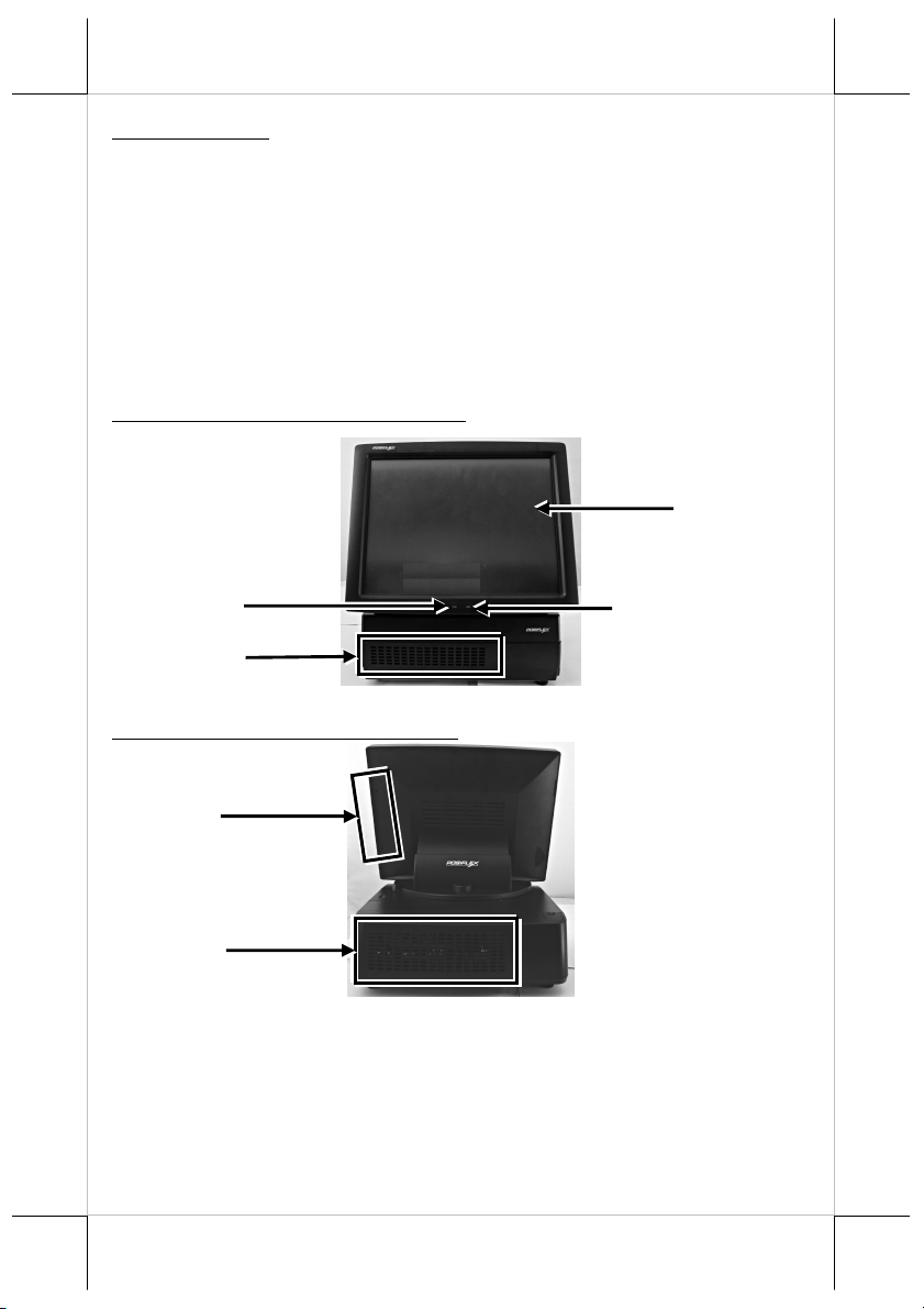
Front View of HT-4712/PB-4700
12-inch LCD Touch Panel
Power LED Indicator
Ventilation Grids
Rear View of HT-4712/PB-4700
Side Mount Upgrade Kit
Ventilation Grids
2
LAN LED Indicator
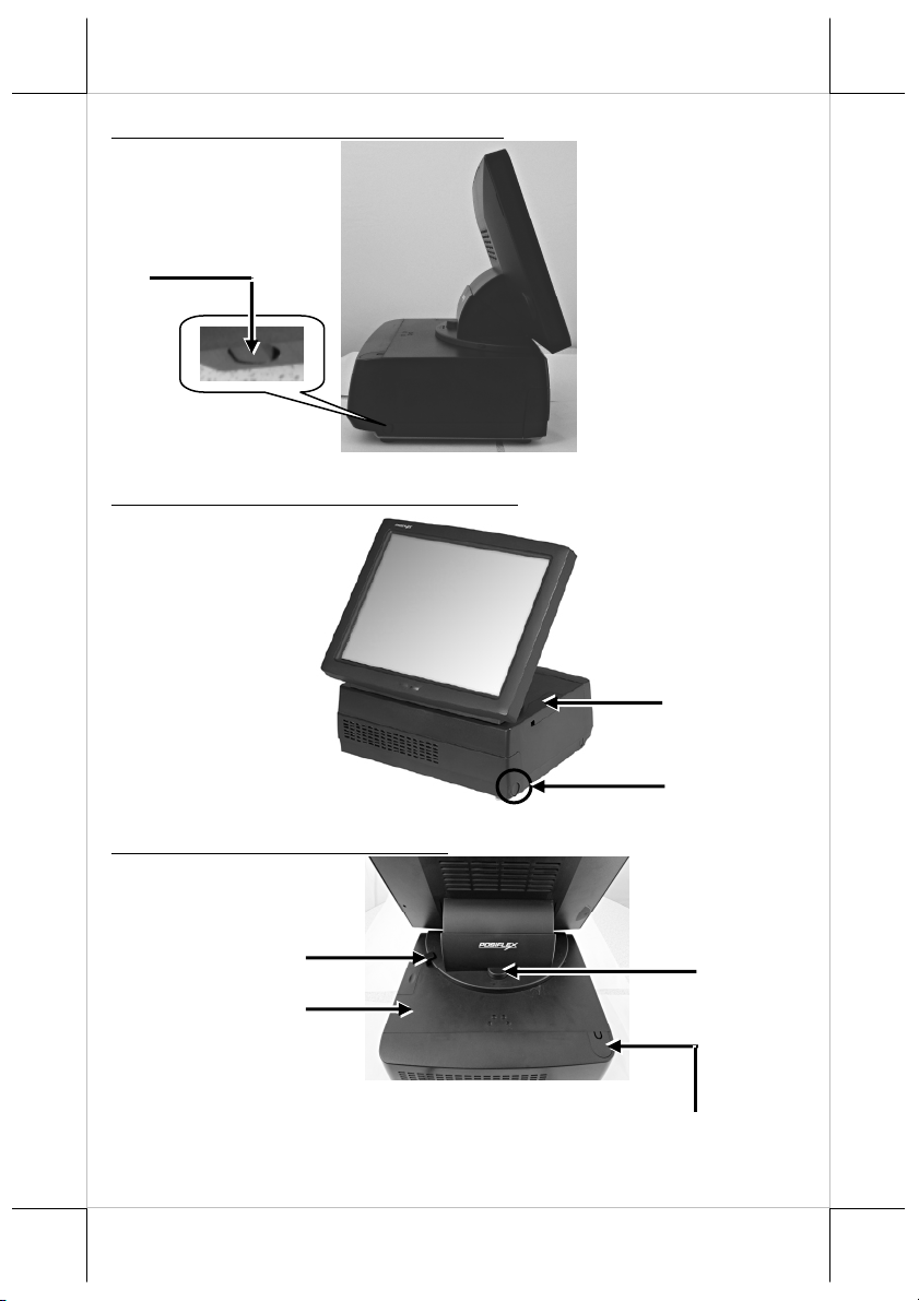
Adjustment Button
Left Side View of HT-4712/PB-4700
I/O-Port Protective Cover
Release Button
Right Side View of HT-4712/PB-4700
Extended USB Port Cover
Top View of HT-4712/PB-4700
Left-Right Viewing Angle
Adjustment Button
Upper Cover
Power Button
Up-Down Viewing Angle
Customer Pole Display
Mounting Portion (Optional)
3
Cushion
2 3 4 5 6 7 8 9 10
12
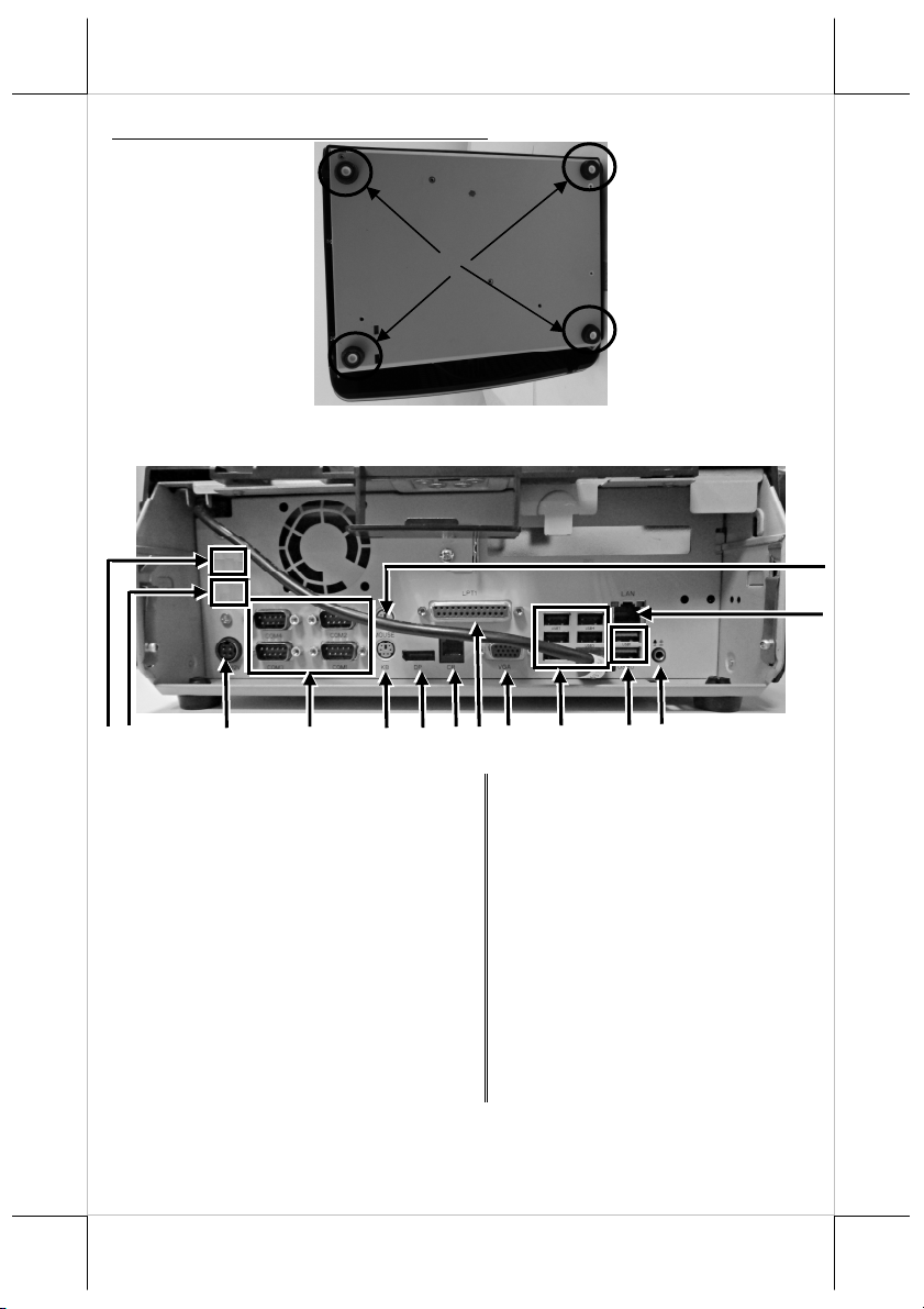
Bottom View of HT-4712/PB-4700
Rubber
View of I/O Interfaces of HT-4712/PB-4700
1
(Reserved for optional
1
PoweredUSB Port or COM port)
3
12V DC-IN Power Jack
5 PS2 Port for Keyboard 6 Display Port
7 Cash Drawer Port 8 Parallel Port
9 VGA Port 10 USB2.0 Port
11 USB3.0 Port 12
13 RJ45 LAN Port 14 PS2 Port for Mouse
2
4 COM1 ~ COM4
11
(Reserved for optional
PoweredUSB Port or
COM port)
MIC-IN / Line-Out for
Combo Jack
14
13
4

Connecting Power Adapter and I/O Cables
Follow the steps listed below to open the rear I/O-port protective
cover and connect cables.
1. Press the release buttons, with
forefingers, on the left and
right sides of the upper cover
of the POS box.
2. Press and hold the upper right
and upper left sections of rear
I/O-port protective cover with
thumbs, and pull outwards the
cover.
3. Remove the rear I/O-port
protective cover.
4. Connect power adapter and
I/O cables to the I/O interface
of the POS box.
1
2
5

Close the rear I/O-port protective cover
Remember to close the rear I/O-port protective cover after
completing in the power adapter and I/O cable connection.
Follow the steps listed below to close the cover.
1. Align the two wedges of the top
of the rear I/O-port protective
cover with the two wedged
portions of the upper cover of the
POS box.
2. Press and hold the upper right
and upper left sections of rear
I/O-port protective cover with
thumbs, and push the release
button of I/O-port protective
cover into the section between
the upper cover and chassis of
the POS box.
Wedged Hole
3. When the release button is
wedged to the wedged hole of
the upper cover, you will hear a
click sound, indicating that the
rear I/O-port protective cover is
well closed.
Powering ON the HT/PB-4700
Then press the power button to power on
the main unit. To power it off, press the
button again.
Once powering off the system, if you want
to power it on again, please wait for at
least 3 seconds.
6

If the system hangs due to a reason, such as software resource
conflict, please press and hold the power button for 10 seconds
around to forcedly shut down the system.
Status LED Indicator
After powering ON the HT/PB-4700 and connecting to the LAN
port, you can read the system operation status from the power and
LAN LED indicators. The LED status is described below.
LED Status Description
POWER
LAN
Solid blue System power ON
Solid orange System standby
Solid green LAN link
Flickering green & yellow Data transmission
Installing an Operating System
This product is highly professional equipment. Therefore, we do
NOT encourage you to install any operating system into this
machine without professional assistance. Posiflex Technology,
Inc. shall not be responsible for any technical support to
questions on this aspect. We suggest that you contact your dealer
for OS installation.
Operating System Recovery
For the HT/PB-4700 main system preloaded with an operating
system on HDD, Posiflex provides a recovery CD shipped with
the main system for the preloaded operating system. The system
integrator shall take care of software restoration after the OS is
recovered.
If you plan to recover your operating system, we do NOT
encourage you to recover any operating system. Please contact
your service center for operating system recovery.
7

Adjustment of LCD Monitor for A Better Viewing Angle
(For HT-4712 Only)
For an optimal viewing angle, follow the steps listed below to
adjust the LCD monitor of the HT-4712.
Vertical Adjustment
1. Press and hold the up-down
viewing angle adjustment
button.
2. Adjust the LCD monitor up
and down around the
directions A and B.
Horizontal Adjustment (from 0° to 16°)
1. Press and hold the left-right
viewing angle adjustment
button.
8

A
B
A
2. Horizontally adjust the LCD
monitor left and right around
the directions A and B.
Optional Upgrade Kits
Posiflex HT/PB-4700 can work with multiple optional upgrade
kits, such as 2nd LCD monitor, customer pole display, side-mount
MSR, keyboard and the like. For the detailed instruction, refer to
the technical manual of HT/PB-4700 or each of the user manuals
of the optional upgrade kits.
Extended USB Port
The extended USB port is provided for connection of the side
mount upgrade kit to the POS box. To open the extended USB,
follow the steps listed below.
1. Press the extended USB port
with thumb or forefinger.
2. Pull and move the cover in the
direction A.
9

3. You will see the extended
USB port through which the
side mount upgrade kit is
connected to the POS box.
Cleaning the Front Ventilation Holes and Grids
Use vacuum cleaner to remove any
dust away from both the ventilation
holes on the front cover and
ventilation grids on chassis
exposed after removal of the front
cover.
To avoid the POS box from being damaged, we suggest you to
contact your local service center for help.
10

Specifications
PB-4700 HT-4712
CPU i3 4330TE / Pentium G3320TE / Celeron G1820
Chipset Intel H81 or optional Q87 for RAID function
Memory Dual channels, DDR3 SO-DIMM x2, 1600MT/s, Max 16GB
OS POSReady 7, Windows 7, Windows Embedded 8.1 Industry, Linux
Display
Display Port 1 port, optional DP to VGA converter for 2nd VGA
VGA
Interface
Storage
Ethernet
Wireless
Power
Supply
Serial Port
Parallel Port 1 port, DB26Pin
CR Port 1 port, controlling 2 cash drawers
USB Port
PS/2 KB Port 1 port, mini-DIN6Pin
PS/2 Mouse
Audio MIC-in / line-out for combo jack
Internal
Speaker
Extension
Power ON
Only Control
DB 15Pin, supporting +12V, enabled by BIOS setting
2 port, SATAIII 2.5" HDD, SATA7Pin x2 / optional 16GB
minimum SSD
10/100/1000 Mb x 1,
Realtek RTL8111F GbE
Optional, 802.11 b/g/n
LAN
Through 12VDC power adaptor, 80W
4 ports, DB9Pin x4 on the rear I/O / COM 1/2/3/4 +5V enabled by
BIOS setting and COM 1/2/3/4 +12V enabled by jumper select
10 ports, rear I/O (USB3.0 + USB2.0 x 2 & USB2.0 x 6), PinHeader x 1 for PU-430 PoweredUSB, and Pin-Header x 1 for touch
controller board
1 port, mini-DIN6Pin
Port
Optional, 1 port, 1.5w mono speaker
PCI-E slot x1, through PCI-E riser card
Slot
Support
(N/A)
12" LCD panel ,1024x768
resolution
11

PB-4700 HT-4712
Power
Switch
Power-ON
Wake-Up
Mechanical
Installation
Indicator
Touch
Controller
Touch
Sensor
Watch Dog Programmable 1~255 sec for system reset
RAID
Function
Power
Saving
COM 5/6
Extension
Cable
PoweredUSB Optional, PU-430 port, 24V x 1, 12V x 1,with 150W power adaptor
Temp &
Humidity
Soft switch
Through alarm/LAN
Desk top
Power on/ standby, bi-color LED indicators
LED
Ethernet link LED on Ethernet connector
(N/A)
(N/A) 5 wires, touch panel
Optional, Q87 support RAID function.
Support Intel DSW mode
Optional, through TX-4600COM daughter board
5V/12V enabled by jumper select
Operation temp.: 0 to 40 ℃ / storage temp.: 20 to 85℃
humidity: 10 to 90 %; 5 to 90 % (operation condition)
USB interface, on the touch &
LVDS board
To get the detailed information on
※※※※
HT/PB-4700, please download the
technical manual of this model from Posiflex Global Website
(http://www.posiflex.com/en-global/Download/download).
12
 Loading...