

Page 1

1
Package Contents
CD-3200U/3201U
CD-3200U/3201U 2D image scanner
ST-8000 scanner holder stand (Optional)
USB cable
Quick setup guide for CD-3200U/R
CD-3200R/3201R
CD-3200R/3201R 2D image scanner
ST-8000 scanner holder stand (Optional)
RS-232 cable
Quick setup guide for CD-3200U/R
18160900030 Ver. B0
http://www.posiflex.com
CD-3200U/R & CD-3201U/R
2D Image Scanner
Quick Setup Guide
Page 2

2
Front View
Rear View
Status
Explanation
Red LED flashes one time
Power On
Blue LED flashes one time
Good read
Trigger Button
Scan
window
Status LED
Product Overview
Scanner Maintenance
The scanner is designed for long-term trouble-free operation and rarely
requires any maintenance. Only an occasional cleaning of the scanner window
is necessary in order to remove dirt and fingerprints.
Wipe the scan window with a soft lint-free cloth and a non-abrasive cleaner to
avoid the scan window from being scratched and damaged. The scan window
can be cleaned while the scanner is running.
The standard interface cable is attached to the scanner with a 10-pin modular
connector. When the connector is properly seated, it is secured in the scanner
by a flexible retention tab. The cable is designed to be field replaceable.
Replacement cables can be obtained from your authorized distributor. To
replace the cable, take the following steps.
1. Make sure the power of both the host terminal and the scanner is powered
off.
2. Disconnect the old scanner cable from the host terminal.
3. Press down the retention tab, and gently pull out the cable.
4. Insert the new interface cable into the bottom of the scanner until it clicks.
Then, plug the new cable into the host.
LED Indication
Page 3

3
Problem
Diagnostic Tips
The scanner is on but cannot read
any barcode.
The scanner window is dirty. Clean the scanner
window as described in the Scanner
Maintenance section.
The presented barcode type is not enabled. Use
this guide to tell the scanner to accept that type
of barcode.
The host terminal has disabled the scanner.
Check the setup of host terminal.
The barcode type presented is not supported by
the scanner.
The scanner does not accept more
than two or three barcode labels.
Determine whether the required barcode types
are enabled or not.
A stray barcode is sitting somewhere in the
scanner field of view. Remove all barcode labels
from the scanner’s scan volume and try again.
The scanner cannot send the data to the POS
system. Make sure that the scanner is installed
well and your host POS system is ready to
receive data.
A barcode is read by the scanner
but not accepted by the POS
system.
The communication settings of the system port
and the scanner do not match. Adjust the settings
to make them match to each other.
The scanner is not installed well. Contact your
dealer for the proper installation. The software
running on the POS system does not support the
data format of the barcode label.
When a barcode stays close to the
scanner, the barcode cannot be read
automatically by the scanner.
Check whether or not you have enabled the
Manual Trigger mode. If you have enabled this
mode accidentally, please disable the Manual
Trigger mode by scanning the “Disable trigger”
barcode in the advanced user manual.
Troubleshooting
This section contains information about how to solve problems that you may
encounter when operating the scanner. If a trouble occurs, please refer to the
following diagnostic tips as a mean to solve the trouble. However, before
referring to the tips, make sure that the scanner is installed well. If the problem
remains, contact your dealer.
Page 4

4
Firmware Version
RS232
USB-HID
Programming Codes
Below are some suggestion you need to bear in mind while scanning labels:
1. The barcode labels shown in bold and black are default factory
settings.
2. Please cover the unwanted codes for scanning the specific barcode
required for the programming to prevent confusion in code scanning.
3. Use the user manual downloaded from our global website or taken from
the Information DVD for advanced programming.
4. Two operational modes, Auto Trigger and Manual Trigger, are provided
to help you manage your daily activities more efficiently via CD-3200
series scanners. By default, both of CD-3200U/R and CD-3201U/R are
set to Manual Trigger.
5. While scanning the setup barcode labels provided in the quick guide, you
need to pull the trigger to initiate the decoding process.
Firmware Version
Scan the below barcode label to retrieve the current firmware version.
User Interface Switch Barcodes with Defaults Setting
Three types of user interface, including RS-232, USB-HID, and USB
virtual COM, are available for you to select. However, after the interface
type is changed, the current settings will be removed and reset to the default
factory settings. If the scanner fails to switch to the desired interface type,
please either re-plug the I/O cable or restart your host terminal, and then
scan the same barcode label to resolve the problem.
Page 5

5
USB-VCP
RS232
USB-HID
USB-VCP
Defaults Barcode Setting
To restore the default factory settings, please select one of three barcodes
listed below.
Page 6

6
Auto Trigger
Manual Trigger
Trigger Mode
In general, two trigger modes, Auto Trigger and Manual Trigger, are
offered to help you engage in routine works efficiently using CD-3200
series scanners. While Auto Trigger Mode is activated, the light source of
your scanner will always stay on in order to detect barcode data any time.
On the other hand, with enabled Manual Trigger Mode, the barcode label
will not be decoded unless the trigger button is pulled.
Auto Trigger Detection Mode
Detection Mode allows you to adjust illumination settings to facilitate the
process of detecting a target code. Through the configurable option, the
status of aiming light can be set to enable or disable. What is more, you
may also arrange the color of illumination in response to the lighting
condition to enhance your scanning performance. However, please be
reminded that Detection Mode only works under the condition that
Trigger mode of CD-3200U/R and CD-3201U/R is set to Auto Trigger.
Regarding each type of available detection modes, the following are related
description for your reference.
Green aiming detection
When a target code falls within the aiming range while the green
aiming light is emitted, the target is detected. It is recommended to
use this mode indoors because the detectability is reduced in an
environment of higher illuminance levels than indoor’s.
Red illumination detection
When a target code falls within the range of the field of view while
the red illumination light is emitted, the target is detected. This mode
can be used in a lighted environment.
Page 7
7
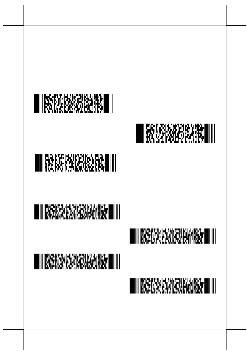
Green aiming detection
Red aiming detection
No illumination detection
Enable UPC
Enable EAN
Enable Code 39
Enable Codabar
No illumination detection
A target code is detected without illumination light. The power
consumption can be reduced, but the response of detection will also
be reduced. Ambient light is used for detection in this mode, so this
cannot be used in a dark place while it can be used in a lighted
environment.
Enabling of readable codes
Page 8
8
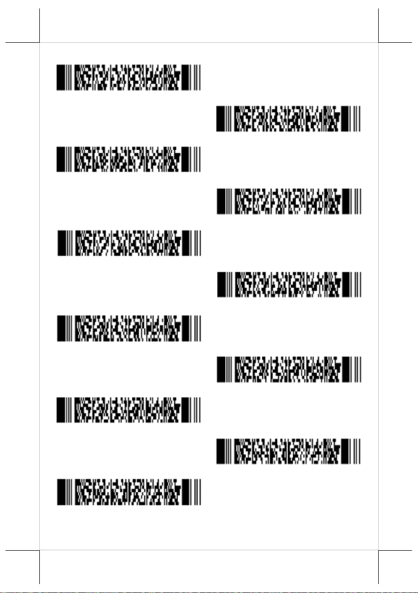
Enable Interleaved 2of5
Enable Chinese Post Matrix 2of5
Enable POSTNET
Enable MSI/Plessey
Enable UK/Plessey
Enable Code 128
Enable GS1-Databar
Enable GS1-Databar Limited
Enable GS1-Databar Expanded
Enable QR Code
Enable PDF417
Page 9
9
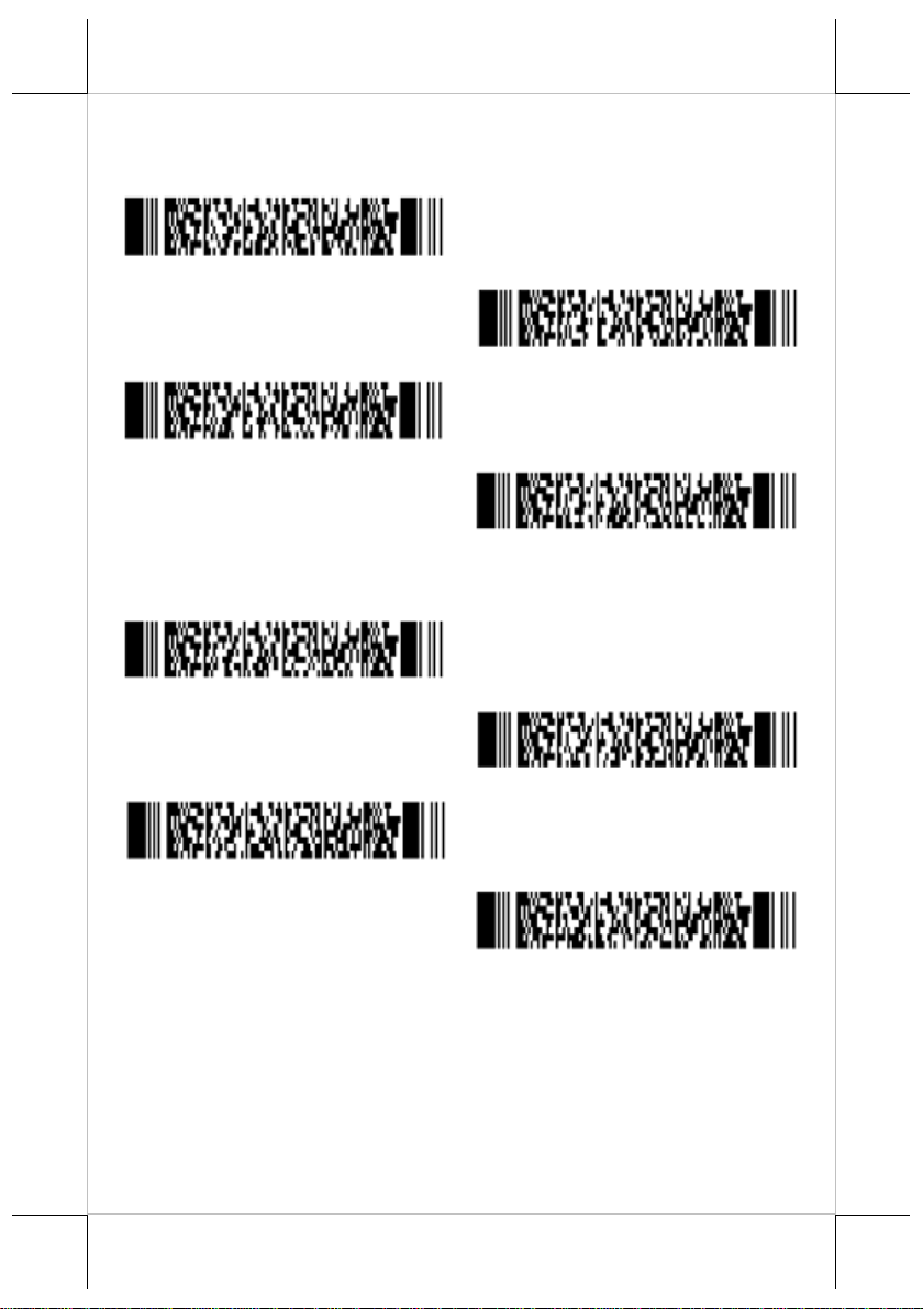
UPC-A, No leading zero, transmit CD
UPC-A, No leading zero, not transmit CD
UPC-A, Leading zero, transmit CD
UPC-A, Leading zero, not transmit CD
UPC-E, No leading digit, transmit CD
UPC-E, No leading digit, not transmit CD
UPC-E, Leading digit, transmit CD
UPC-E, Leading digit, not transmit CD
Setting code specific options
Options for UPC-E
Page 10
10
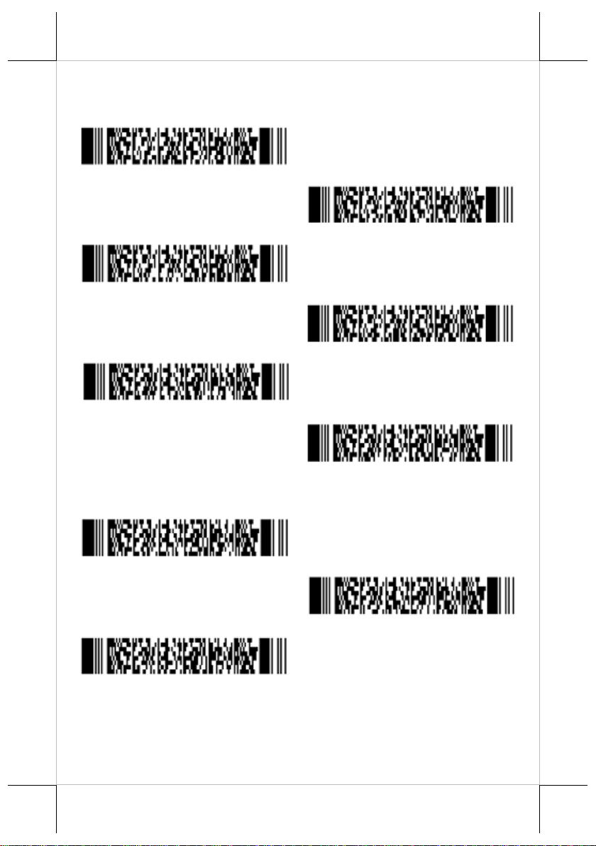
EAN-13 not transmit CD
EAN-13 transmit CD
EAN-8 not transmit CD
EAN-8 transmit CD
Disable ISBN translation
Enable ISBN translation
No case conversion
Convert to upper case
Convert to lower case
Options for EAN-13 and EAN-8
Case conversion
Page 11
11
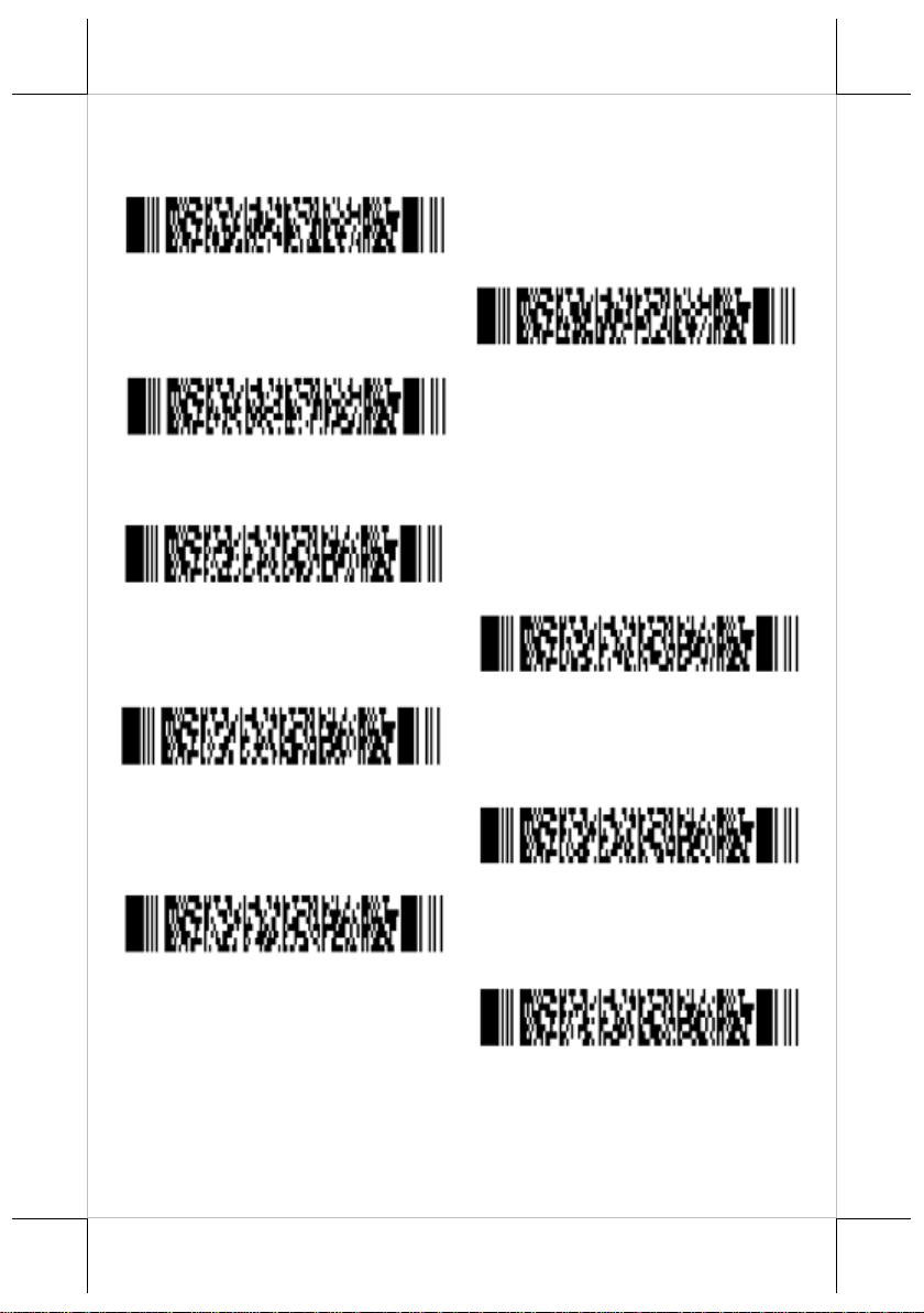
Disable floodlight
Enable floodlight
Alternating floodlight
Disable buzzer
Enable buzzer
Single tone buzzer
High - low buzzer
Low - high buzzer
Buzzer duration 200 msec
Floodlight and aiming options
Buzzer settings
Page 12
12
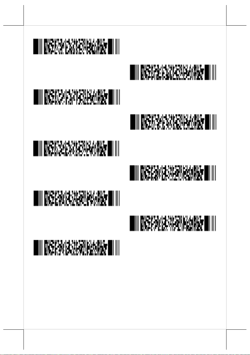
Buzzer duration 400 msec
Buzzer loudness: Maximum
Buzzer loudness: Loud
Buzzer loudness: Normal
Buzzer loudness: Minimum
Buzzer before transmission
Buzzer after transmission
Disable startup buzzer
Enable startup buzzer
Page 13
13
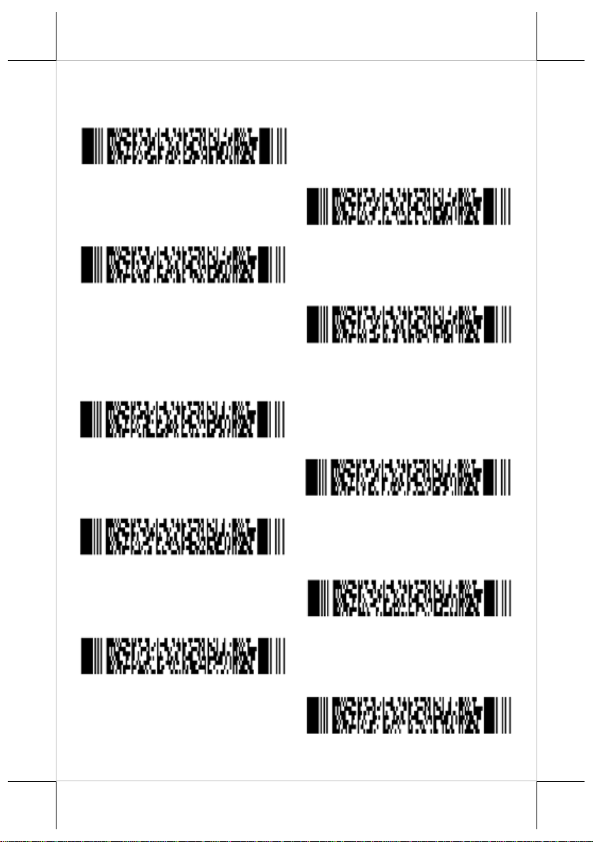
9600 baud
19200 baud
38400 baud
57600 baud
7 data bits
8 data bits
No parity
Even parity
Odd parity
1 stop bit
Baud rate settings
Data, parity and stop bits
Page 14
14
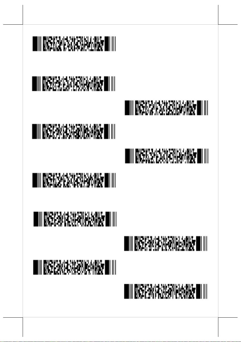
2 stop bits
No handshake
Busy/ready
XON/XOFF
ACK/NAK
Flow Control time out 200ms
No delay
20 ms delay
50 ms delay
100 ms delay
Handshaking barcode setting
Intercharacter delay for RS232
Page 15
15
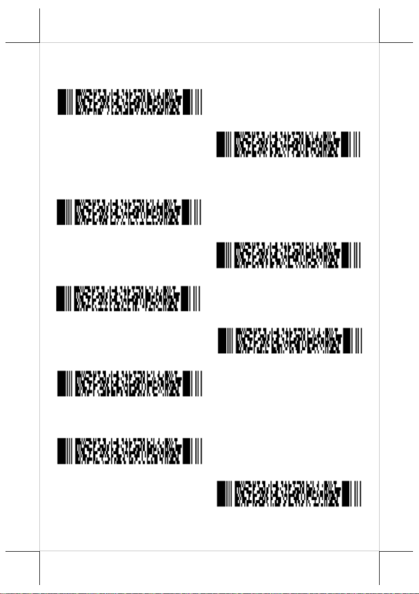
With keyboard
Without keyboard
US
German
French
Dutch
Japanese
Do not use numpad
Use numpad
Keyboard wedge/USB options
Keyboard language
Special options
Page 16
16
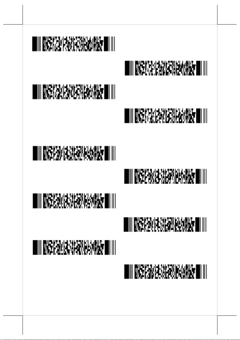
Auto numlock mode
No CAPSLOCK mode
CAPSLOCK mode
Auto CAPSLOCK mode
No delay
Delay = 1
Delay = 3
Delay = 5
Delay = 7
Delay = 9
Intercharacter delay for wedges/USB
Page 17
17
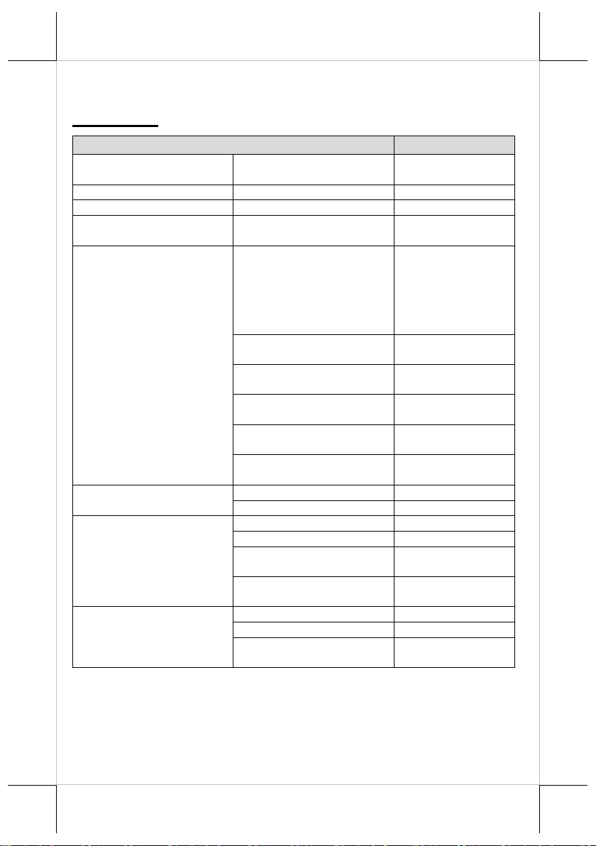
Item
Characteristics
Scan method
CMOS area sensor (black
and white)
-
Number of effective pixel
(H) x (V)
752 x 480 dot
Image capture speed (*1)
Frame rate
60 fps
Focal distance
From the front edge of scan
engine
130 mm
Depth of field (mm)
Code 39
50~120mm
(Resolution(0.127))
35~190mm
(Resolution(0.25))
70~210mm
(Resolution(0.33))
Code 128
45~180mm
(Resolution(0.25))
UPC
30~210mm
(Resolution(0.33))
PDF417
30~175mm
(Resolution(0.25))
QR Code
20~170mm
(Resolution(0.381))
DataMatrix
40~145mm
(Resolution(0.31))
View angle
Horizontal
Approx. 40.6˚
Vertical
Approx. 26.4˚
Auxiliary light source (LED
x 2)
Red LED
-
Peak Wave Length
617 nm
Directivity angle 2Θ1/2
(*2)
60 ˚
Maximum radiation output
(*3)
15000 mcd
Light Source for aiming
(LED x 1)
Green LED
-
Peak Wave Length
528 nm
Maximum radiation output
(*4)
18700 mcd
Specifications
CD-3200U/R
*1 The fastest speed of image capture
*2 The reference value extracted from the LED datasheet
*3*4 The reference value extracted from the datasheet
(conditions: 25℃, IF = 140mA)
Page 18
18
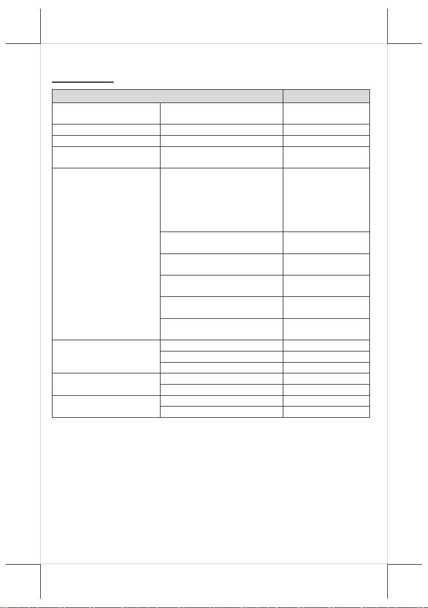
Item
Characteristics
Scan method
CMOS area sensor
(black and white)
Global shutter
Number of effective pixel
(H) x (V)
640 x 480 dot
Image capture speed (*1)
Frame rate
100 fps
Focal distance
From the front edge of scan
engine
120 mm
Depth of field (mm)
Code 39
30~105mm
(Resolution(0.127))
35~200mm
(Resolution(0.25))
65~230mm
(Resolution(0.33))
Code 128
45~200mm
(Resolution(0.25))
UPC
30~270mm
(Resolution(0.33))
PDF417
15~175mm
(Resolution(0.25))
QR Code
20~185mm
(Resolution(0.381))
DataMatrix
20~150mm
(Resolution(0.31))
View angle
Diagonal
Approx. 46.4˚
Horizontal
Approx. 38.0˚
Vertical
Approx. 26.4˚
Auxiliary light source
(LED x 1)
Color
Warm white LED
Color Temperature
2600 ~ 3700K
Light Source for aiming
(LED x 1)
Color
Green LED
Peak Wave Length
525 nm
CD-3201U/R
*1 The fastest speed of image capture
Page 19

19
<MEMO>
Page 20

20
<MEMO>
 Loading...