

POSBank SlimPOS User Manual

More than just a POS, you think
POSBANK Co., Ltd
Room 805~808, New T Castle B/D, 429-1, Gasan-Dong, Geumcheon-Gu, Seoul,Korea
www.posbank.com
User's MANUAL

INDEX
Product quality guarantee
Copyright
Disclaimer
Trademark recognition
Federal Communication Commission
Declaration of conformity
Caution for safety
Check the contents
Option device
Each part of main body name
Front image
Rear image
Rear connection I/O
Customer Display (VFD) installation
Second Display installation
Chapter 1. Caution. Chapter 3. BIOS Setup Utility Chapter 5. Mainboard Jumper Setting
Chapter 6. Replacing Parts
Chapter 4. Trouble shooting
Chapter 2. Product Overview.
BIOS set up utility
BIOS menu screen
Standard CMOS features
Advance BIOS features
Advance chipset features
Integrated peripherals
Power Management set up
PnP/PCI configurations
PC Health Status
Load set up defaults
Set passwords
Save & Exit setup option
Exit without saving
General checkout guidelines
Power system checkout
Network symptom
MSR symptom
USB s
Cash drawer
LCD screen
Touch screen
Power
PS/2 KB
Boot
ymptom
symptom
symptom
symptom
symptom
symptom
symptom
Motherboard and deeps
location description
Safety and Precautions
Before you Begin
Remove rear cover method
Replace motherboard method
Replace MSR method
Replace memory method
Replace Heatsink & FAN method
Replace CUP method
Replace HDD method
Remove power supply method
Replace monitor method
Replace LCD panel, mother board,
touch screen methods
Reference to upgrade
Power supply
Specifications
4
5
6
7
8
9
10
12
12
13
13
13
14
15
15
43
47
48
49
50
53
54
55
56
57
58
59
60
63
63
64
17
19
20
21
22
23
29
31
32
33
34
35
36
38
38
39
39
39
40
40
40
41
41
41

Caution.
Chapter 1.

Product quality guarantee
PO SBAN K war ran ts our hardwa re PO S t e rmin al pro duct and its par ts agai nst defects i n mat eria ls and work mans hip und er
no rmal use fo r a sta ndard p erio d o f two (2) ye ar from the date of origina l purcha se.
Du ring this peri od, POSB ANK wil l repa ir or rep lace a d efe ctiv e p ro d uct or par t with out cha rge for par t s a nd l abor to the
pu rch aser .
Th e 1 st yea r is free workm ansh ip and new or re furb ishe d replac e ment parts with o ne-way fre ight cost born by POS BANK
an d c ustom er shal l b e respon sibl e for sen d shi ppin g c harg e.
2n d year is als o n o c harge for wor kmans hip and par ts but lim ited war ran ty with round- w ay freigh t c o st born by c u stom er.
Products outs ide of the warran t y p eriod or sco p e s hall be diag nose d at cus t omer 's expense.
PO SBAN K wil l requ ire cus t omer 's re pair and pay ment aut horization t o p ro c e ed with any rep airs.
>>
4

Copyright.
This publication, including all photographs, illustrations and software, is protected under international copyright laws, with all rights reserved.
Neither this manual, nor any of the material contained herein, may be reproduced without written consent of the author.
>>
5

Disclaimer.
The information in this document is subject to change without notice.
The manufacturer makes no representations or warranties with respect to the contents hereof and specifically disclaims any implied warranties
of merchantability or fitness for any particular purpose.
The manufacturer reserves the right to revise this publication and to make changes from time to time in the content hereof without obligation of
the manufacturer to notify any person of such revision or changes.
>>
6

Trademark recognition
>>
All product names used in this manual are the properties of their respective owners and are acknowledged.
7

Federal communications commission (FCC)
>>
This equipment has been tested and found to comply with the limits for a Class A digital device, pursuant to Part 15 of the FCC Rules.
These limits are designed to provide reasonable protection against harmful interference in a residential installation.
This equipment generates, uses, and can radiate radio frequency energy and, if not installed and used in accordance with the instructions, may
cause harmful interference to radio communications.
However, there is no guarantee that interference will not occur in a particular installation.
If this equipment does cause harmful interference to radio or television reception, which can be determined by turning the equipment off and on, the
user is encouraged to try to correct the interference by one or more of the following measures:
- Reorient or relocate the receiving antenna.
- Increase the separation between the equipment and the receiver.
- Connect the equipment onto an outlet on a circuit different from that to which the receiver is connected.
Shielded interconnect cables and a shielded AC power cable must be employed with this equipment to ensure compliance with the pertinent RF
emission limits governing this device.
Changes or modifications not expressly approved by the system's manufacturer could void the user's authority to operate the equipment.
8

Declaration of conformity
>>
This device complies with part 15 of the FCC rules. Operation is subject to the following conditions:
- This device may not cause harmful interference, and
- This device must accept any interference received, including interference that may cause undesired operation.
9

Caution for safety.
>>
- Specifications are subject to change without notice.
- Avoid exposing the product to direct sunlight and do not use the product near area of high moistures.
- Do not block the unit's ventilation openings.
- Do not attempt to disassemble or modify this product by yourself, as doing so may expose you to an electric shock.
- All servicing should be performed by qualified personnel and should confirm to all local codes.
- If and abnormal power conditions or blackouts occur during operation, disconnect unit at the AC source immediately.
- Once normal power is restored, reconnect the AC source.
- To avoid unit failure or intermittent operation, check power and other I/O cables are connected correctly.
- Always unplug the power cord from the AC outlet before cleaning the product. Use a soft cloth to clean the product.
Do not use solvents or abrasives and do not spray or pour any liquid directly onto product's screen or case.
10

Product overview
Chapter 2.
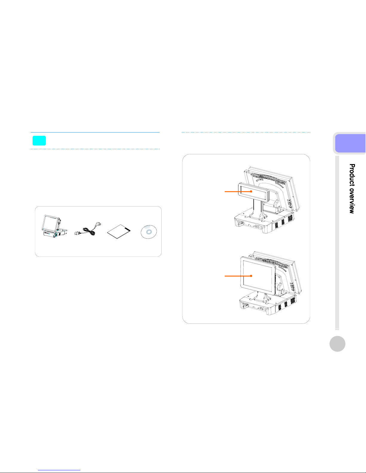
Check the contents
>>
1. The following items are included when you purchased
this product.
2. If any of these items are damaged or missing, contact
your dealer for assistance.
3. Optional Parts
POS MAIN BODY
POWER CORD
USER'S MANUAL,
DRIVER CD
Customer display
with stand
second display
with stand
12
2
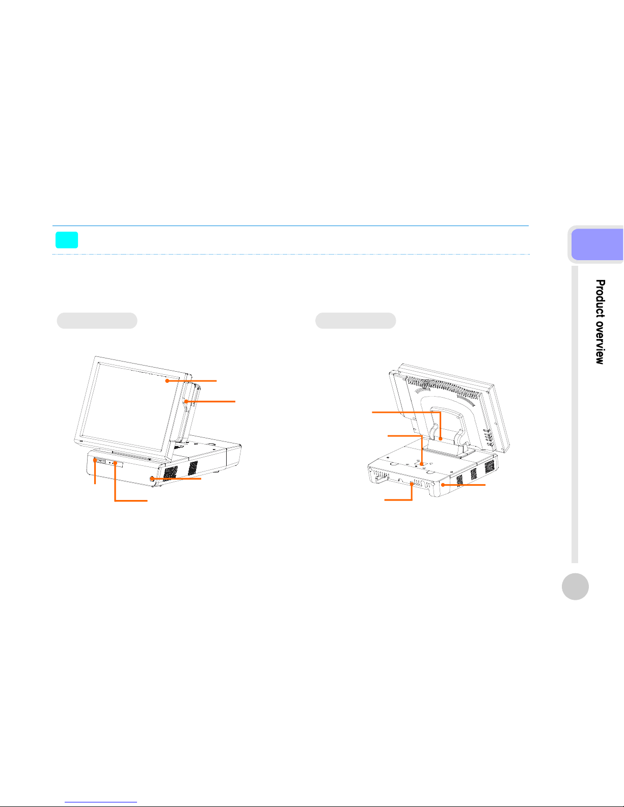
Each part of main body name
>>
Touch
Panel Display
MSR
Power Button
POWER·HDD·LAN LED
USB PORT
Display Hinge
Customer Display
Cover
Real For Cable
Management
Real Connectors
FRONT VIEW REAR VIEW
13
2
Each part of main body name
>>
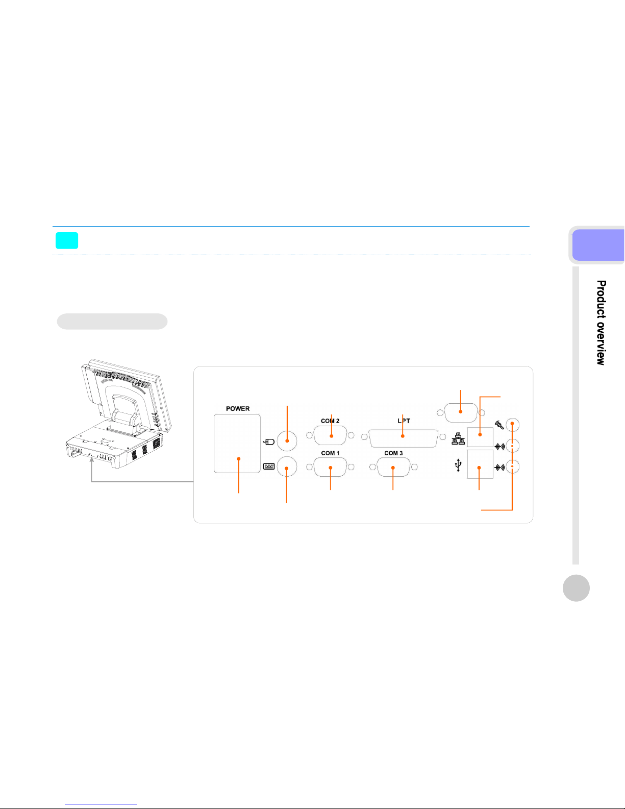
Rear Connectors I/O
AC IN POWER
Connector
PS/2 KEYBOARD
Connector
COM1 Port COM3 Port USB Port
Audio port (Line in, Speaker out, Mic in)
Monitor Connector
(option)
Parallel PortCOM2 Port
PS/2 Mouse
Connector
LAN
Connector
14
2
Option parts installation
>>
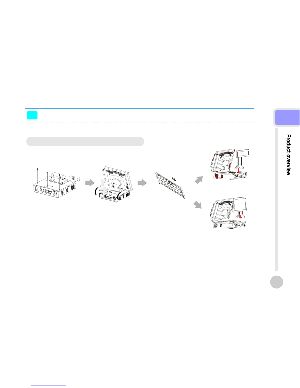
Customer Display(VFD) & 2nd Monitor Installation
Connect the display cable and insert VFD(2nd Monitor) set,
use 4 screws to secure the VFD(2nd Monitor) set.
VFD(2nd Monitor) is connected to internal COM4.
To install or withdraw VFD(2nd Monitor), power must be switch off.
Caution;
15
2

Chapter 3.
BIOS Setup Utility
Bios setup utility
>>
This motherboard supports a programmable firmware chip that you can update using the provided utility.
Use the BIOS Setup program when you are installing a motherboard, reconfiguring your system, or prompted to "Run Setup."
This section explains how to configure your system using this utility.
Even if you are not prompted to use the Setup program, you can change the configuration of your computer in the future.
For example, you can enable the security password feature or change the power management settings.
This requires you to reconfigure your system using the BIOS Setup program so that the computer can recognize these changes
and record them in the CMOS RAM of the firmware hub.
The firmware hub on the motherboard stores the Setup utility. When you start up the computer, the system provides you with
the opportunity to run this program.
Press <Del> during the Power-On-Self-Test(POST)toenter the Setup utility; otherwise, POST continues with its test routines.
If you wish to enter Setup after POST, restart the system by pressing <Ctrl+Alt+Delete>, or by pressing the reset button on the
system chassis.
You can also restart by turning the system off and then back on. Do this last option only if the first two failed.
The Setup program is designed to make it as easy to use as possible.
Being a menu-driven program, it lets you scroll through the various sub-menus and make your selections from the available
options using the navigation keys.
■ The default BIOS settings for this motherboard apply for most conditions to ensure optimum performance.
If the system becomes unstable after changing any BIOS settings, load the default settings to ensure system
compatibility and stability.
Select the Load Optimized Defaults from the BIOS menu screen.
■ The BIOS setup screens shown in this section are for reference purposes only, and may not exactly match what you
see on your screen.
17
3
Bios setup utility
>>
The keys in the legend bar allow you to navigate through the various setup menus
Saves changes and exits SetupF10
Loads the fail -
safe / optimized defaults
F6, F7
Loads the previous valuesF5
Change color from total 16 colors. F2 to select color forward, (
Shift) F2 to select color backward
(Shift) F2 key
Moves the cursor to the last field- or PgDn
Moves the cursor to the first field+ or PgUp
Brings up a selection menu for the highlighted field.Enter
Move to previous or next item↑, ↓
Move to the item in the left or right hand←, →
Return to the main menu from a submenu or prompts you to quit the setup program.Esc
General help, only for Status Page Setup Menu and Option Page Setup MenuF1
Function DescriptionKey(s )
-
Function DescriptionKey(s )
18
3
Bios setup utility
>>
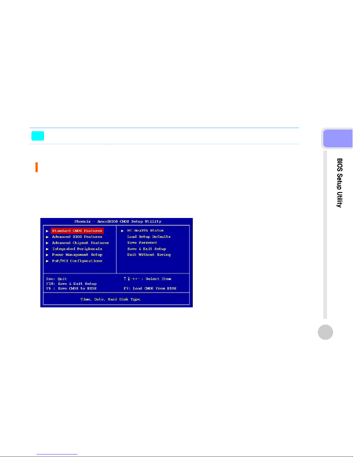
BIOS Menu Screen
When you enter the BIOS, the following screen appears.
The BIOS menu screen displays the items that allow you to make changes to the system configuration.
To access the menu items, press the up/down/right/left arrow key on the keyboard until the desired item is highlighted,
then press [Enter] to open the specific menu.
19
3

Bios setup utility
>>
Standard BIOS Features.
The Standard CMOS Features screen gives you an overview of the basic system
Set the system to halt on errors according to the system functions
specified in each option.
Configuration options: [All Errors] [No Errors] [All, But Keyboard]
Halt On
Date [Day, xx/xx/xxxx]
Time [xx:xx:xx]
IDE Channel 0/1 Master / Slave
Video
The date format is <week>, <month>, <day>, <year>.
The time format is <hour><minute><second>, based on the 24-hour
clock.
- IDE HDD Auto-Detection : [Press Enter] to select this option for automatic device detection.
- IDE Primary Master :
[Auto]: Automatically detects IDE devices during POST
[None]: Select this when no IDE device is used.
The system will skip the auto-detection setup to make system start up faster.
[Manual]: User can manually input the correct settings.
- Access Mode: The options are CHS/LBA/Large/Auto
- Capacity: Capacity of currently installed hard disk
- Cylinder: Number of cylinders
- Head: Number of heads
- Precomp: Write precomp
- Landing Zone: Landing zone
- Sector: Number of sectors
This category detects the type of adapter used for the primary monitor that
must match your video display card and monitor.
- EGA / VGA: Enhanced Graphics Adapter/Video Graphics Array.
For EGA, VGA, SVGA, or PGA monitor adapters.
- CGA 40: Color Graphics Adapter, power up in 40 column mode.
- CGA 80: Color Graphics Adapter, power up in 80 column mode.
- MONO: Monochrome adapter includes high resolution monochrome adapters.
20
3
 Loading...