

POSBank miniQ User Manual


-2-
CONTENTS
Chapter 1. Introduction
Chapter 3. BIOS Setup Utility
Chapter 5. Motherboard
1-1. Warranty ………………………………………………….
3
3-1. BIOS Setup Program …………………………………..
33
5-1. Motherboard Layout ………………………………………………
76
1-2. Copyright ………………………………………………..
4
3-2. BIOS Menu Screen ………………………………...…...
36
5-2. Clearing CMOS ……………………………………………………….
78
1-3. Safety Information ….………..…………………….
4
3-3. Standard CMOS Features …………………………..
37
5-3. Serial Port Power Jumper Settings………………………….
79
1-4. Liability Limitation ………..…………………………
5
3-4. Advanced BIOS Features ..…………………………..
40
5-4. STACON1 ………………………………………………………………..
80
1-5. Installation Recommendations ……………….
7
3-5. Advanced Chipset Features ………………………..
46
3-6. Integrated Peripherals ………………………………..
49
3-7. Power Management Setup ………………………...
57
Chapter 2. Product Overview
3-8. PnP/PCI Configuration …..……………………………
61
Chapter 6. Maintenance
2-1. Inside Your Package ………………………………..
8
3-9. PC Health Status …………………………………………
63
6-1. Safety Warning ……………………………………………………….
81
2-2. Pre-installation Preparation ...………………….
13
3-10. Load Optimized Defaults ………………………….
66
- HDD Replacement ...…………………………………………………..
82
2-3. Product Outline .……………………………………...
13
3-11. Set Supervisor Password ………………………….
67
- Motherboard Replacement .………………………………………
84
2-4. Installation of Optional Devices ……………..
17
3-12. Set User Password ……………………………………
69
- Memory Replacement ……………………………………………….
86
- CDP Installation ……………………………………………
17
3-13. Save & Exit Setup …………………………………….
71
- SSD Replacement ………………………………………………………
87
- Mini Keyboard Installation …………….…….……...
19
3-14. Exit Without Saving ………………………………….
72
- MSR Replacement ……………………………………………………..
88
- Connection via USB Port .…………………………….
20
- Paper-Roll Replacement …………………………………………….
89
- Connection via Ethernet Port (LAN) ……….…..
21
Chapter 4. Troubleshooting
- Printer Replacement ………………………………………………….
90
- Cash Drawer Connection ……………………..……...
22
4-1. Network Issues …………………………………………...
73
6-2. Technical Specifications ………….…..……………..…………..
92
- Power Cable Connection ..…..…………………........
23
4-2. MSR Issues ………………………………………………….
73
- miniO Main Unit ………………………………………………………..
92
2-5. Basic Operations ……………………………………….
24
4-3. USB Issues ……………………………………………….….
74
- Integrated Printer …………………………………….………………..
94
- Switching On POS ………….…………………………….
24
4-4. LCD Issues …………………………………………………..
74
- Shutting Down POS ……………………………………..
25
4-5. Touch-screen Issues ……………………………….…..
74
- Integrated Printer: Control Panel ..………...…….
26
4-6. Power Issues …………………….…………………………
75
- Integrated Printer: Self-test ..…….………..………..
27
4-7. Booting Issues …………….……..……………………….
75
- Integrated Printer: DIP Switch Settings ...…….
28
4-8. Printer Issues ……………………...………………………
75

-3-
Chapter 1. Introduction
1-1. Warranty
We guarantee our POS terminal product and its parts against defects in materials and workmanship, under proper use, for a standard period of
2 years from the original date of purchase.
During this period, we will repair or replace defective and/or faulty products or parts without charge to the customer for parts and labor.
The 1st year includes servicing and new or refurbished replacement parts free of charge, with one-way shipping costs borne by the seller. The
customer shall, however, be responsible for the return delivery costs.
The 2nd year also includes free of charge servicing and parts, but a limited warranty requires the entire shipping cost to be borne by the
customer.
Products out of the warranty period or scope shall be diagnosed at the customer's expense.
In the case of product damage due to error on part of the consumer, incorrect usage, carelessness or natural phenomenon, the customer shall
bear the full cost for both repair and delivery.

-4-
1-2. Copyright
This publication, including all photographs, illustrations and software, is protected under international copyright law with all rights reserved to the
manufacturer. Neither this manual, nor any of the material contained herein, may be reproduced without express written consent of the author.
1-3. Safety Information
1. Always ensure that the correct power voltage is used as a precaution against fire and electrical shock.
2. Avoid exposing product to direct sunlight. Do not use product in areas of high humidity.
Doing so may cause low reliability and/or operational malfunction.
3. Be careful of static electricity on PCB of system with anti-static appliances. Doing so may cause inferior reliability and shorted product life.
4. Keep product away from highly static areas. This may lead to inferior performance and reduced life cycle.
5. Do not interfere with, or obstruct metal components inside product. Doing so may cause the risk of fire or electric shock.
6. Do not pull on power cable or peripheral devices‟ connector cable. Doing so may cause fire, electric shock or electronic system malfunction.
7. Use caution when around other electronic devices with possible high frequency or electro-magnetic effects e.g. Audio, Electronic-range etc.
Doing so will lead to the serious risk of product malfunctioning or a system error occurring.
8. Ensure that batteries are replaced correctly. Failure to do this may result in sudden explosions.
9. Dispose of used batteries properly according to the instructions.

-5-
1-4. Liability Limitation
● Installation and maintenance
We recommend that you inquire about product installation, maintenance and repair service from the official service center and agent office.
POSBANK takes no responsibility for malfunctions or system errors occurring after service and/or system check carried out by unofficial service providers.
● High frequency appliances
This product is qualified by FCC, CE, EMI and MIC compliances, and is thus governed by these qualifications‟ safety regulations.
However, the product can affect and be affected by other high frequencies generated around it. As such, POSBANK does not consider liability for any system
error or disorder due to this issue.
● Electronic noise emitting equipment
We recommend using the product away from electronic noise emitting equipment such as heaters, motors, fluorescent lights, TVs etc. as it may cause
interruption or interference with normal operation.
● Installation location
For optimal performance, the product should be kept in an environment of lower than 65% humidity and in a temperature of 10 ~ 30℃. Please also keep
away from direct sun-light.

-6-
● Cleaning procedure
Cleaning with chemical based products (in particular those containing benzyl or chemical thinning agents) can damage the exterior surfaces of the product.
We recommend using a soft damp cloth and wiping gently, taking particular care when dealing with the LCD display screen.
● Product limitations
1. The use of this product for anything other than POS tasks is strictly prohibited.
The product is not supported for regular PC and interface operation.
2. This product is for business use only, and not for usage in the home.
3. Both hardware and software are both fully configured.
4. Normal operating is guaranteed on a steady power connection.

-7-
1-5. Installation Recommendations
1. Avoid installing during thunderstorms. (Possibility of dangerous exposure to electricity.)
2. Install away from damp spaces or water-leaks.
3. Beware of static occurrence during installation.
4. Use only ground connected and quality certified power cords and cables.
5. Keep out of direct sun-light, extremely high or low temperatures, or high humidity areas.
6. Install product away from areas prone to shocks or vibration.
7. Install product away from sewing machines, welding equipment, electric stoves, audio equipment and other high frequency generating
equipment.
8. Installation and use in close proximity to an air-conditioning unit is not recommended.
9. Do not connect cables underneath carpets or floorboards.
10. Only use power cables supplied by pre-approved and certified venders.
11. Never use power cords from high power source appliances.
e.g. Electronic heaters, Electric stoves, Audio equipment, Air-conditioners, Refrigerators etc.
12. The use of multiple connections in a shared power outlet/socket is not recommended.

-8-
Chapter 2. Product Overview
2-1. Inside Your Package
1. Please check your package and confirm its contents.
2. The POS terminal main unit, power cable, user manual, roll paper and driver CD are included in the package. If any items are missing or
damaged, please contact your dealer for assistance.
» All user manuals and drivers are available for download on our website: www.posbank.com

-9-
[Package Contents]
miniO main unit
User manual Power cable
Driver CD Roll paper
-10-
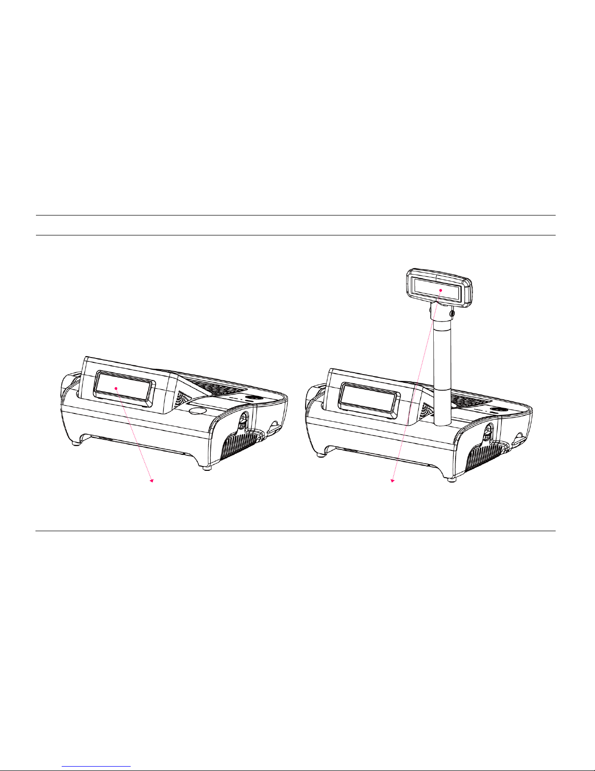
[Optional: Customer Display (CDP)]
Normal CDP
Pole type CDP
-11-
[Optional: PLU Keyboard]
PLU Keyboard: 55Key
Image of Main Unit with PLU Keyboard

-12-
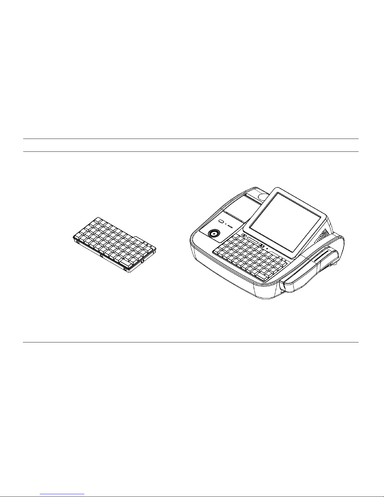
[Optional: Mini Keyboard]
Mini Keyboard
Image of Main Unit with Mini Keyboard

-13-
2-2. Pre-installation Preparation
1. Remove protective film from touch-screen to prevent possible operating difficulties.
2. Attach all optional parts before setting up the main POS unit.
2-3. Product Outline
- Each part of product may differ depending on the specific POS model.
- Model-specific data sheets are provided on our website at www.posbank.com.
-14-
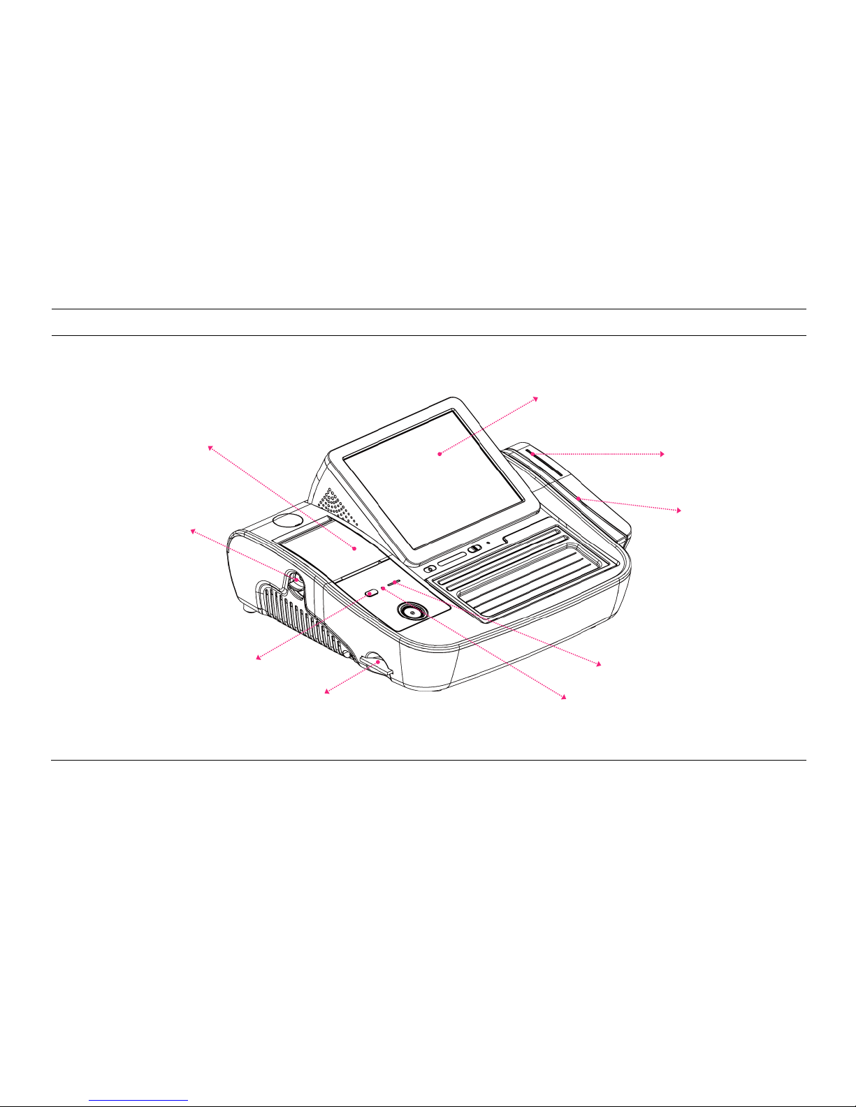
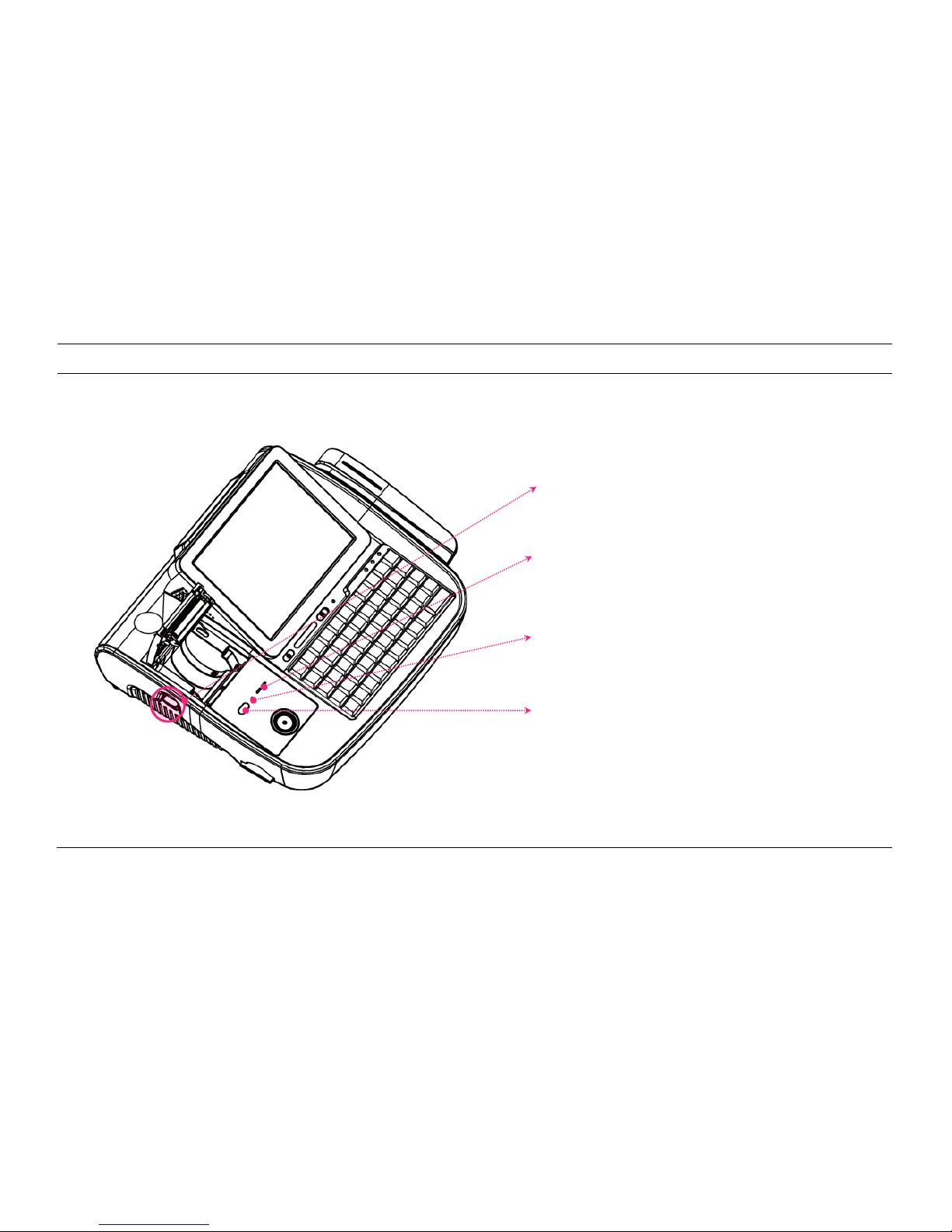
[Side View]
2” Printer
Printer OPEN button
Printer FEED switch
CF card socket
LCD & Touch-panel display
Smart Card Reader
(SCR)
Magnetic Stripe
Reader (MSR)
Printer RESET switch
Printer ON, Error LED
-15-
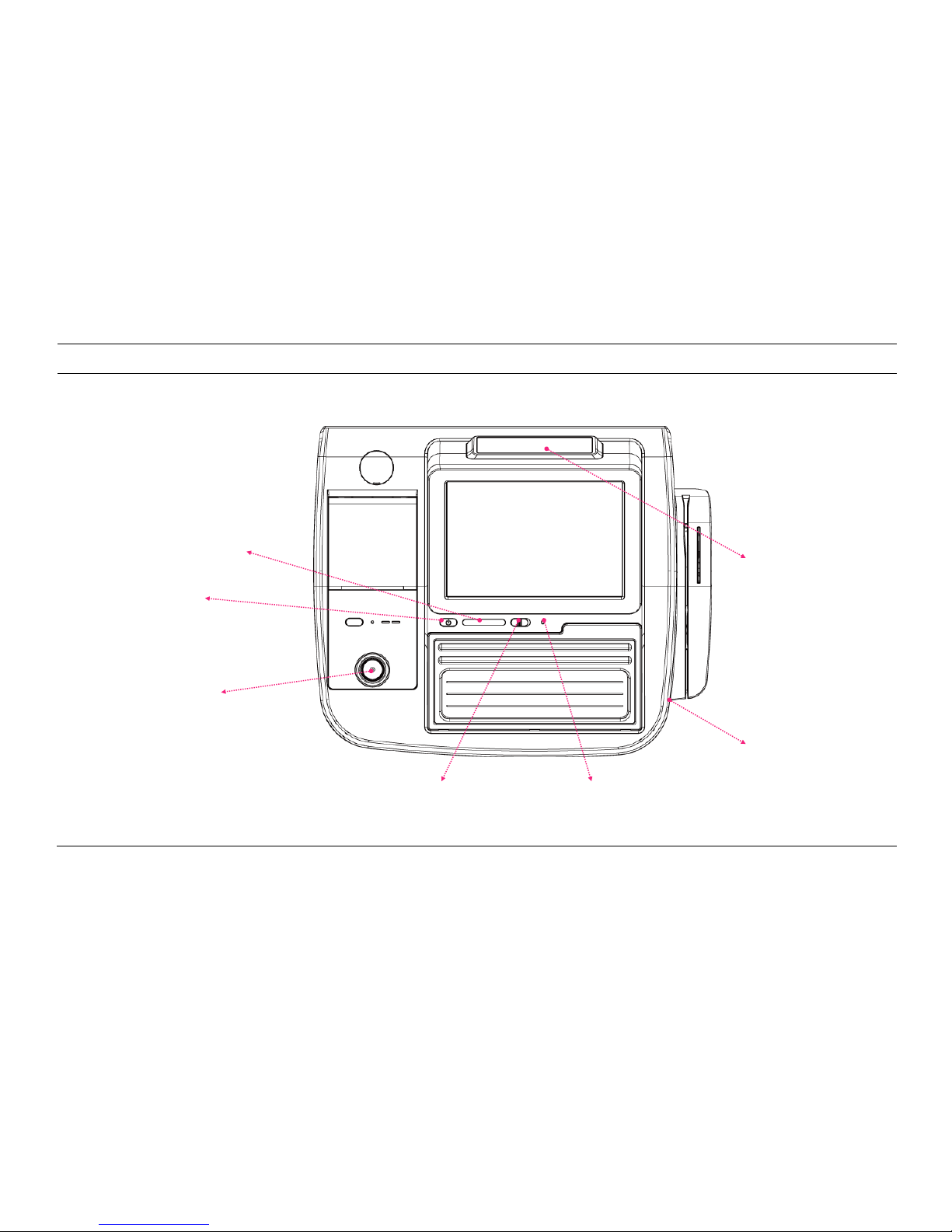
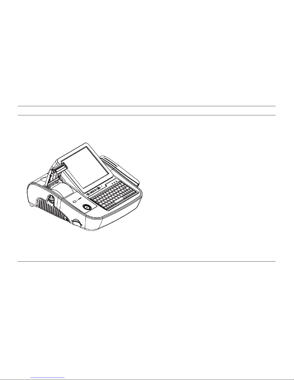
[Top View]
Customer display
(optional)
Power, HDD, LAN LED
Power switch
I-Button
Keyboard LOCK switch
RESET switch
USB port
-16-
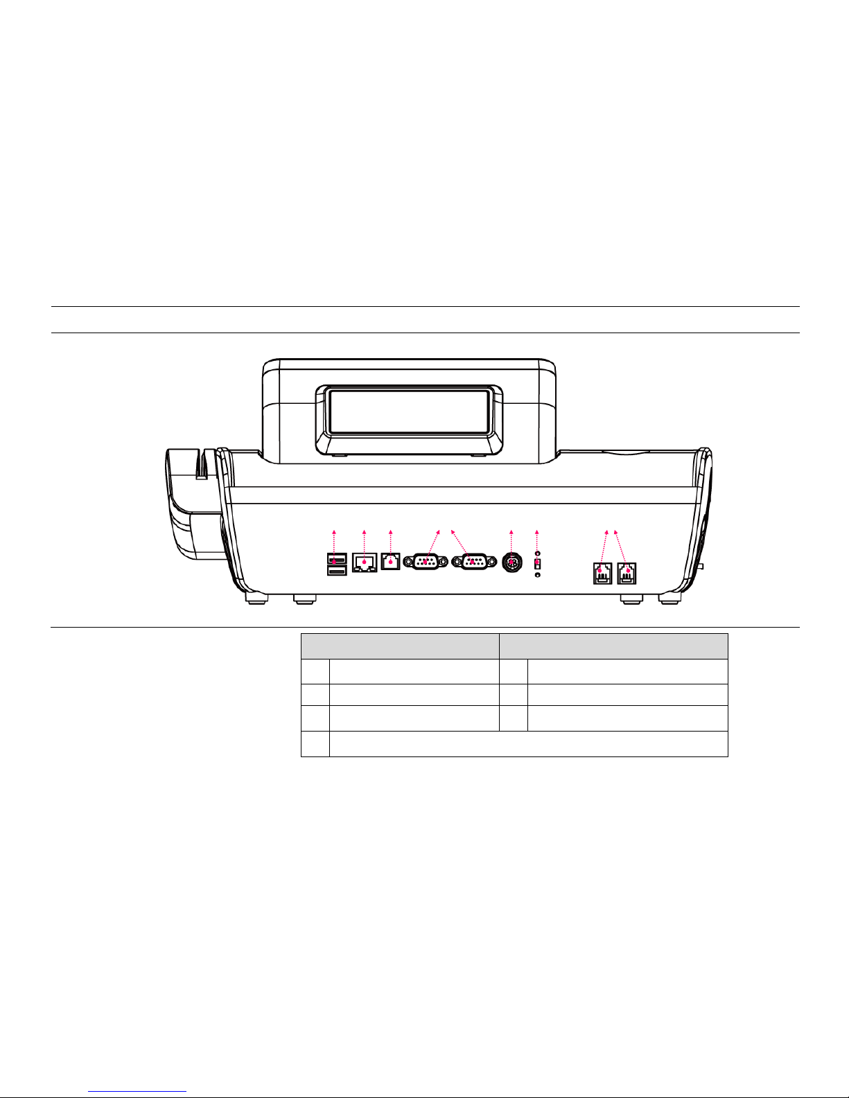
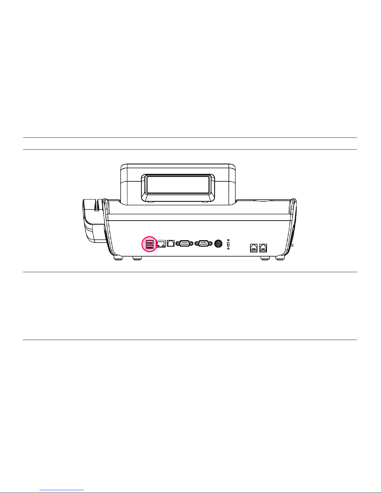
[Power & I/O Ports]
Description
Description
1
USB port
5
Power connector
2
Ethernet port (LAN)
6
Fiscal / PC switch
3
Cash box port
7
Modem port
4
COM1, COM2 port
① ② ③ ④ ⑤ ⑥ ⑦
-17-
2-4. Installation of Optional Devices
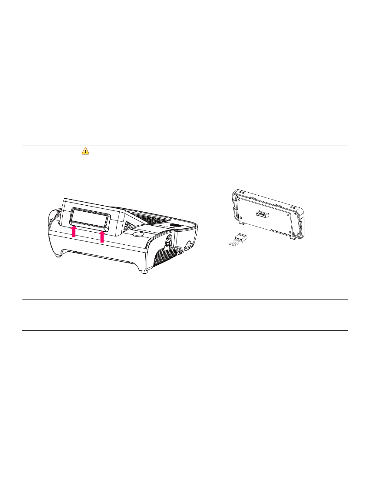
[CDP Installation] Warning: Completely remove power cable when opening main unit or installing optional devices.
1. Insert (-) driver in the grooves marked ↑ and detach cover from main unit.
2. Connect to the main unit using the CDP-cable and install.
After successful installation of O/S,
default text will be displayed on the CDP
upon the POS unit being reset.
-18-
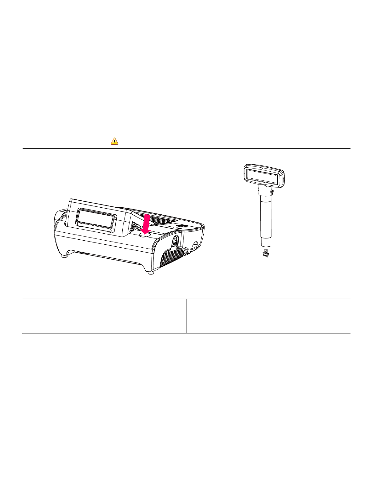
[CDP Installation: Pole Type] Warning: Completely remove power cable when opening main unit or installing optional devices.
1. Insert (-) driver in the grooves marked ↑ and detach cover from main unit.
2. Connect to the main unit using the CDP-cable and install.
After successful installation of O/S,
default text will be displayed on the CDP
upon the POS unit being reset.
-19-
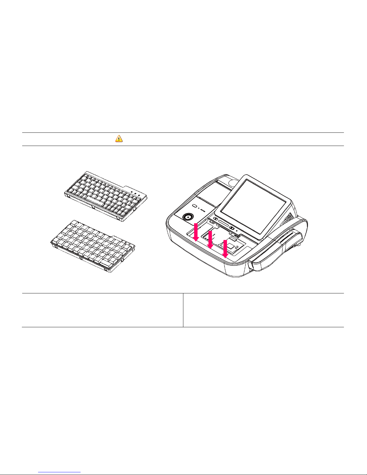
[Mini Keyboard Installation] Warning: Completely remove power cable during installation
1. Put (-) driver in the grooves marked ↓ and detach dummy cover from
main unit.
2. Connect cable to interface connector.
3. Insert keyboard into main unit from above.
*After successful installation of O/S, an LED will light up in the upper-left
corner of the keyboard upon the POS being reset.
-20-
[Connection via USB Port]
Three USB ports are provided in the POS unit, two at the rear I/O and one at the side, all of which support the standard USB 2.0.
Some USB devices (optional devices) are only functional with specific driver software installed.
If multiple USB devices are used together, this may result in abnormal functionality.
Using a USB hub with external adapter for supplying power is recommended.
Dependent on the type of device, it is possible for the USB device to be recognized later than normal.
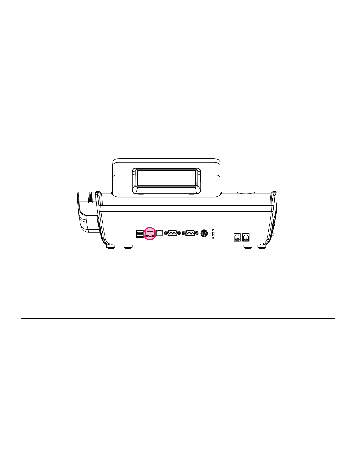
-21-
[Connection via Ethernet Port (LAN)]
The Ethernet port located at the rear I/O supports 10/100/1000Mbps using an RJ45 connector cable.
When connected properly, the LAN LED light will be switched on.

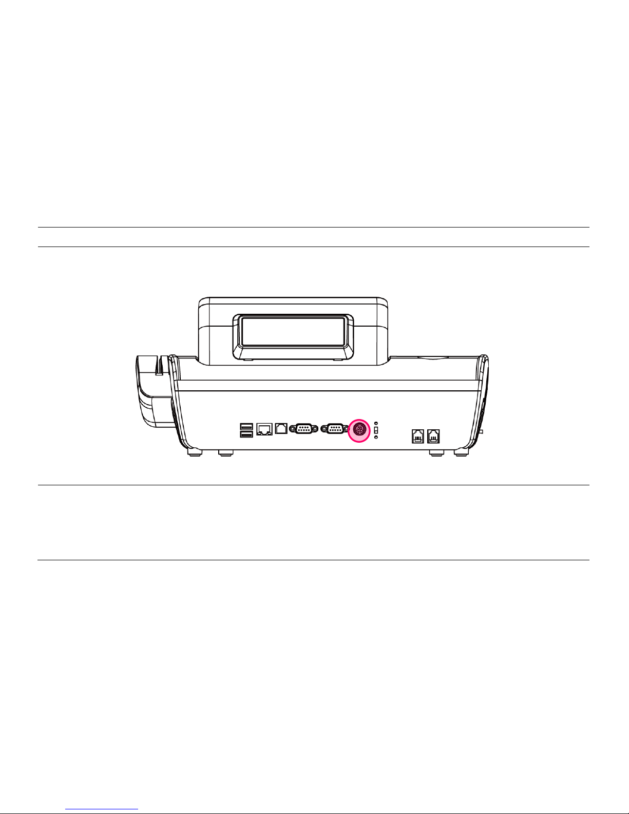
-22-
[Cash Drawer Connection]
The cash drawer port (RJ11) is located at the rear I/O, and supports 24V Solenoid type.
The cash drawer port is connected to the internal printer on the mother board. The POS will not operate properly if no printer is attached to
the POS.
* The miniO
only
supports cash drawers that are compatible with EPSON.
-23-
[Power Cable Connection]
Insert power cable into power connector socket.
INPUT: 100-240V~,50/60Hz 1.5A OUTPUT: DC 24V 2.5A
-24-
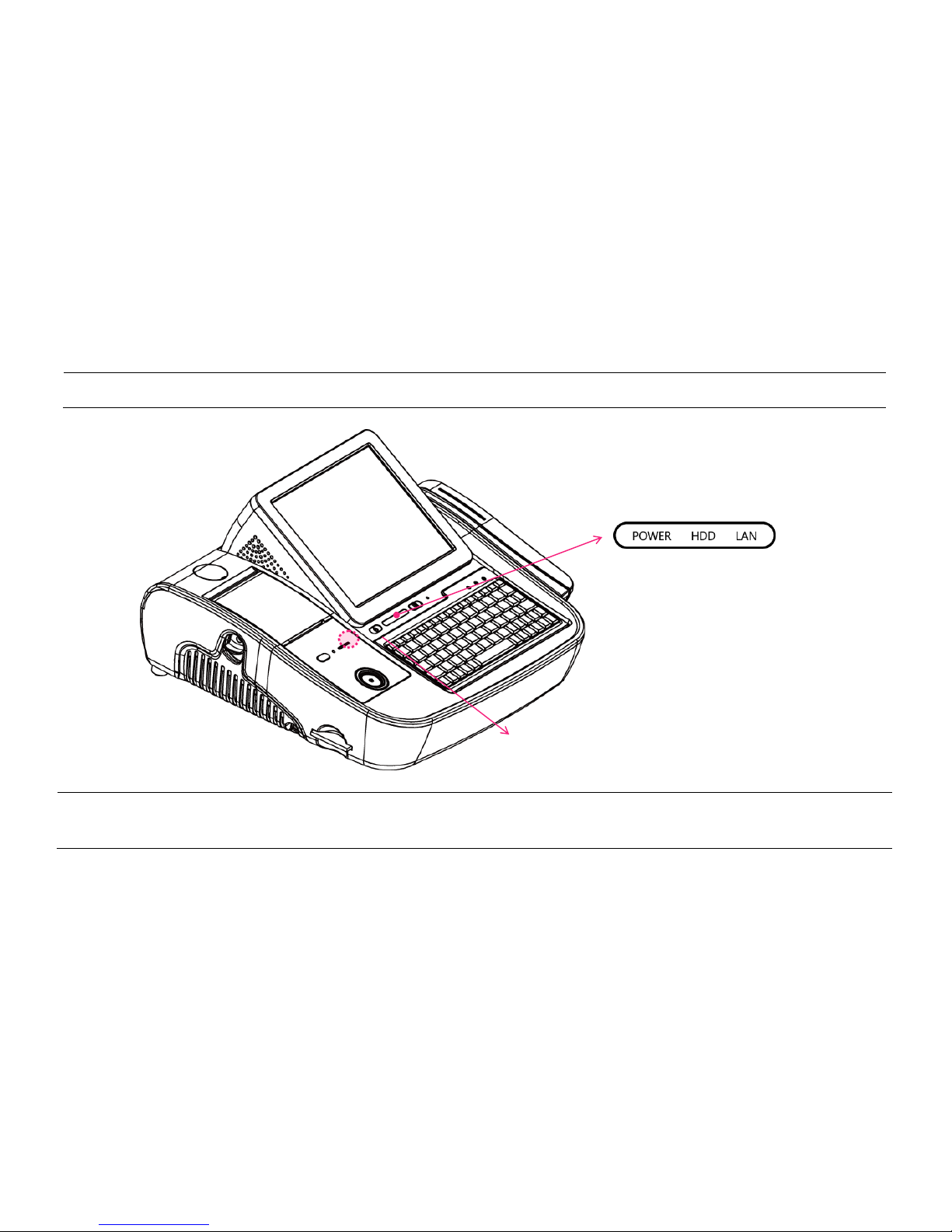
2-5. Basic Operations
[Switching On POS]
» Ensure that all additional POS accessories and peripherals are switched on before switching on the POS.
1. Press „Power‟ button on the POS unit. (POWER LED will light up.) 2. Confirm that Windows is booting.
Power switch

-25-
[Shutting Down POS]
For product stability, it is recommended closing Windows directly in the O/S by clicking „Start‟ -> „Turn Off Computer‟ -> „Shut Down‟.
Please make sure that you have closed all applications before terminating Windows.
* Alternatively, you may shut down Windows by simply pressing the „Power‟ switch on the Main Unit.
You may also perform a system-reboot by pressing the „Reset‟ button on the Main board.
Power button
Main board reset
button
-26-
[Integrated Printer: Control Panel]
OPEN (Button): Press to open the integrated printer.
FEED (Button): Press the FEED button once to discharge
extra paper. Holding down the FEED button will discharge
paper continuously until the button is released again.
PRINTER ON, ERROR LED: Displays: Printer status;
Error; Paper-shortage.
RESET (Button): Reset printing data to initial stage
-27-
[Integrated Printer: Self-test]
1. Ensure the paper roll is installed correctly.
2. The self-test prints out the current firmware version and DIP switch
settings.
3. Self-test 1 (When miniO is powered Off)
While holding down the FEED button, turn on the power to begin the
self-test.
4. Self-test 2 (When miniO is powered On)
While holding down the printer RESET button, press the FEED button.
Next, release the printer RESET button and the self-test will begin.
5. Two pages will be printed in total:
1. Current printer status
2. Font display
6. Upon completion of the self-tests, press the RESET button to resume
operation.
-28-
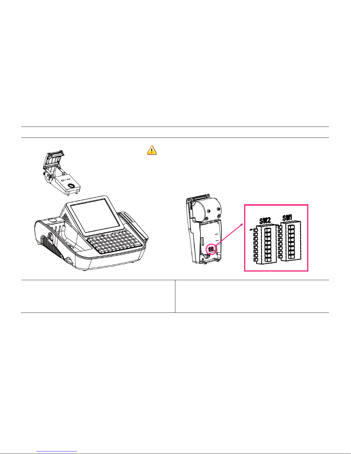
[Integrated Printer: DIP Switch Settings]
1. Detach integrated printer from main unit.
2. Check DIP SW on underside of printer.
Warning: Ensure power is OFF when changing the dip switch settings.
Tip: Change density setting to "Normal" when printing with "B" Font

-29-
No
Function
Setting
Default
1
RS232-C
(Transmission
speed)
SW1-1
SW1-2
SW1-3
9600 BPS
2400 BPS
OFF
OFF
OFF
4800 BPS
ON
OFF
OFF
9600 BPS
OFF
ON
OFF
19200 BPS
ON
ON
OFF
38400 BPS
OFF
OFF
ON
57600 BPS
ON
OFF
ON
115200 BPS
OFF
ON
ON
2
RS232-C
(Handshaking)
SW1-4
DTR/DSR
DTR/DSR
OFF
XON/XOFF
ON
3
Auto
cutter
SW2-7
Enable
Enable
OFF
Disable
ON
4
Sound
SW1-5
SW1-6
No Sound
No Sound
OFF
OFF
Internal
buzzer
ON
OFF
External
buzzer
OFF
ON
Voice
ON
ON
 Loading...