

POSBank Anyshop II Installation Manual
The one
that
creates a
new
trend
AnyShop II
Precaution
e Warranty
We
guarantee our
POS
terminal product
and
its parts against defects
in
materials
and
workmanship under proper
use
for a standard period
of
2 years from the date of
original purchase.
During this period,
we
will
repair or replace defected and/or faulty products or parts
without imposing a charge for spare
and
labor
to
the purchaser .
The
1st year includes servicing
and
new or refurbished replacement parts free of
charge, with one-way shipping cost born
by
the seller; the customer shall
be
responsible for return delivery charge .
The
2nd
year also includes free of charge servicing
and
parts, but a limited warranty
requires the entire shipping cost
be
borne
by
the customer.
Products out of the warranty period or scope shall
be
diagnosed at customer's
expense.
We
will
charge for repair
and
delivery
in
the
case
of damage
as
a result
of
the customer's mistake, abnormal usage, carelessness or natural disasters .
e Notice
for
safety
1.
We
recommend using proper power voltage
as
a precaution against fire
and
electrical shock.
2.
Avoid
exposing
the
product
to
direct sunlight
and
do
not
use
the product near areas
of high moisture ; this may cause low reliability and/or operational malfunction .
3.
Be
aware of electro-static
on
PCB
of system with anti-static appliance; This is a
possible cause of low reliability
and
short life term .
4. Place a product
away
from highly static areas; this may lead
to
low performance
and
a reduced life cycle.
5.
Do
not disturb metal material or obstacle
in
product
in
danger
of
fire
and
electric
shock.
6.
Use
product
in
simple power cord plug-in circumstance
in
caution
of
fire, electric
shock
and
system disorder
on
electricity.
7.
Be
careful of other electronics with possible high frequency, electronic
and
magnetic affects
lEx.
Audio,
Electronic-range, etc]; there
is
a strong possibility this
will
lead
to
the product becoming out-of-order or system
error
.
8. Risk of explosion if battery is replaced incorrectly; dispose of
used
batteries
according
to
the instructions.
9.
Only
use
adapter supplied.
If
an
incorrect adapter is not used, the product's performance may decrease
and
there
is
an
increased risk of fire or electric shock.
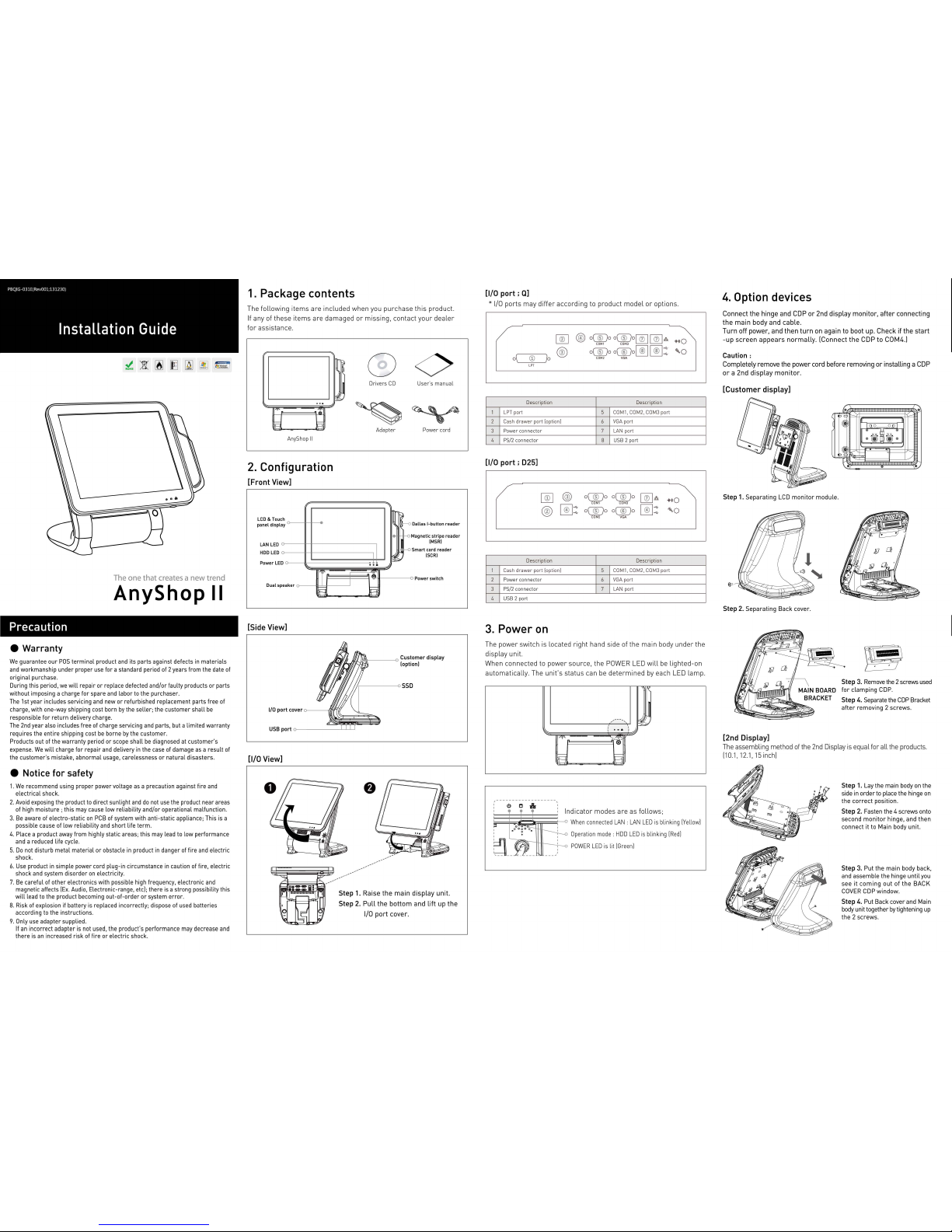
1.
Package contents
The
following
items
are
included
when
you
purchase
this
product.
If
any
of
these
items
are
damaged
or
missing,
contact
your
dealer
for
assistance.
AnyShop
II
2.
Configuration
[Front View]
ch LCD &
lou
panel displ
LAN LED
HOD
LED
Power LE
ay
D
Dual
sp
eaker
o----
[Side View]
[1/0 View]
ITI
§
I
~
...
----------""
O<>
Dri
vers
CD Use
r" s ma
nual
Ad
apte
r Power cord
~~I
Dallas !-button
reader
II
IH
"'
~
•
~
M
~
5
~;;.'
agnetic
stripe
reader
(MSR)
mart card
reader
(SCR)
Power switch
~~~
---------
Step
1.
Raise
the
main
display
unit.
Step
2.
Pull
the
bottom
and
lift
up
the
1/0
port
cover.
[1/0 port ;
Q]
*
1/0
ports
may
differ
according
to
product
model
or
options.
1
2
3
4
~
o\'"
-----c®=---...Jo
@)
LPT
Description
LPT port
Cash
drawer
port (option)
Power
connector
PS/2 connector
[1/0 port ; 025]
Descripti
on
1
Cash
drawer
port (opti
on)
2
Power connec t
or
3 PS/2 connector
4 U
SB
2 port
3.
Power
on
@)
o
(ID
o
o
(IDo~
~.:0
oooo
oooo[~J
C®J
::
COM2
VGA
Description
5
COM1. COM2.
COM3
port
6
VGA
port
7 LAN port
8 U
SB
2 port
o
(IDo o(
®
)o
l(?5l
a
COM1
COM3
~
o
(IDo o(
®
)o
~
::
COM2 VGA
Description
5
COM1. COM2.
COM3
port
6
VGA
port
7
LAN
port
The
power
switch
is
located
right
hand
side
of
the
main
body
under
the
display
unit.
When
connected
to
power
source,
the
POWER LED
will
be
lighted-on
automatically.
The
unit's
status
can
be
determined
by
each
LED
lamp.
-
~
'
...
...
"!"
...
--~'
a=l
h
ll:-i
Indicator
modes
are
as
follows;
~~
:;iE§§
~~~
~
When connected
LAN
: LAN
LED
is
blinking [Yellow]
Operati
on mod
e:
HOD
LED
is
blinking
[Red]
POWER
LED
is lit
[Green]
4.
Option devices
Connect
the
hinge
and
COP
or
2nd
display
monitor,
after
connecting
the
main
body
and
cable
.
Turn
off
power,
and
then
turn
on
again
to
boot up.
Check
if
the
start
-up
screen
appears
normally.
[Connect
the
COP
to
COM4.)
Caution:
Completely
remove
the
power
cord
before
removing
or
installing
a COP
or a 2nd
display
monitor.
[Customer display]
Step
1. Separating
LCD
monitor
module.
Step
2. Separating Back cover.
[2nd Display]
0 0 0 0
~-
~
j l
\.~··
............
......
........
...........................
.
·
·~
Step
3.
Remove
the 2 screws
used
for
clamping
COP
.
Step
4. Separate
the
COP
Bracket
after
removing 2 screws.
The
assembling
method
of
the
2nd Display is
equal
for
all
the
products.
[10.1, 12.1,15 inch]
Step
1. Lay the main body
on
the
side
in
order
to
place the hinge
on
the
correct
position.
Step
2. Fasten the 4 screws onto
second
monitor
hinge, and then
connect it to Main body unit.
Step
3. Put the main body back,
and assemble the hinge until
you
see
it
coming
out
of
the
BACK
COVER
COP
window.
Step
4. Put Back cover and Main
body
unit together
by
tightening
up
the 2 screws.

HINGE CAP
(upper
side)
2nd
LCD HINGE
HINGE CAP
(lower
side)
CABLE
Step
5. Fit Lower hinge cap
under
Hinge to put holes in the same place .
Step
6. Tighten up the 2 screws
from
the bottom side.
Step
7. Place Hinge
rubber
!made of silicon) onto
COP
window.
Step
8. Carefully push
and
insert
2nd
LCD
monitor
hook
into
the
grooved
hinge
.
Step
9. Atta ch
monitor
unit to hinge
using
the
4 s
cre
ws
and
Connect
the
cable
.
Step
9.
Assemble
the
two
2nd
LCD
caps
.
*
CAUTION
: Beware of the parts where
grooves are located at the bottom .
Step
1 0. Carefully
equip
tou
ch monitor
and Tighten th e re
ar
screws in the
direction of
'"
LOCK'"
[2nd
HOD
Replacement]
QM77
Step
1.
Remove tw o screws
from
the mainboard.
Step
2.
Separate the mainboard .
Step 3. Connect the
SECOND
HOD
cables to the indicated locations.
02550
Step 4.
Pull
the
cable
out
of
the
indicated place
on
the BRACKET.
Step 5. Attach the
MAINBOAD
BRACKET and tighten 2 screws
Step
6.
Assemble the
HOD
and
connect a cable.
5.
Setup optional item
[MSR Replacement]
Step 1. Remove 2 screws
from
side using hand . las show n above)
Step 2. Detach cable
from
MSR
unit.
-MSR is no w remo ved-
Step 3. Replace
MSR
and reassemble a new unit using the reverse
procedure of steps 1-2 above.
6.
SSD
replacement
Step 1. Raise the main display unit.
Step
2.
Pull
the bottom and lift up the
1/0
port
cover.
Step
3.
Pull
out the
SSD
cover
from
the
bottom a
nd
remove.
Step 4.
Press up as shown and
SSD
will
be
ejected.
Step
5.
Insert new
SSD
and put the
cover
on
.
~-~:-----------
0;;
,~----
____
:~~::::-------
'
~ ·~
·
-----
\
/~,'
\
-----
' ' '
',,___ _ __
/ !
~
--
-----
-- --
- -
\~:;;
~
f/
o Specification
CP
U
Chipset
Storage
Memory
Graphi
c
AMT
Display
Touch
sc
reen
Internal
I/O
U
SB
Serial
Port
Custome
r Display
Extension Sl
ot
Pri
mary
Display
External
I/O
U
SB
PS
/2
Serial
Port
L
AN
Audio
Displ
ay
port
Options
Parallel port
Side
USB
Speaker
MSR
Serial
Port
SCR
Back up
battery
Dallas
key
Cash Drawer port
Cu
stome
r display
2nd
LCD
2nd
Storage
Wifi
Operating
Storage
Qualification
Power
OS
Support
Dimension
riJI_
Q
SE
RIE
S.
uPGA988 f
or
3rd Generation I
nte
l® Core™ i7/i5/i3 Intel At
om
processor 02550
~~t=;:~~:a=:~(~~e~~;~
-
~=
(
1MB
Cache, 1.86GHz.
Dua
l CoreforCedarview-0)
lntei QM77 Intel NM10
SATA 3-2.5
inch HOD
or
SSD
(Max. 2 Optional)
SATA 2-2.5 inc
h H
OD
or
SSD
(Max.
2 Optional)
Support
Rai
d 0, 1
Supoo
rt
AHCI Support
AHC1
DDR3
-1600MHz
SODIMM
Default
2GB
(MAX.
8GB)
DDR3
-1600MHz
SODIMM
2GB
(MAX. 4GB)
Integrated Intel
GFX
In
teg
rat
ed
Int
el
GMA
HD
3650
Suppo
rt iAMT 8.0
15"
LED
Backlight LCD 250
cd/
m' (1024 x 768 resol
utio
n)
Tr
ue
Flat Capacit
ive
or 5-wir
ed
Res
istive T
ouch
I 5
-wi
red
Res
isti
ve Touc
h
3 Ports (reserved f
or
touch controll
er,
MSR
reader, mini
PCie)
COM 5 (reserved
for
cash dr
awe
r p
ort
) & COM 6 (reserved for
MSR)
L
VDS
or
VGA & COM 4 (reserved for
COP)
I VGA & COM 4 (reserved
for COP)
Min
i PCie
24b
it L
VDS
Rea
r 6
(USB
3.0 x 4 ports,
USB
2.0 x 2
ports)
I Rear 4 (
USB
2.0 x 4 ports)
1 Po
rt
(reserved
for
Keyboard & Mouse)
COM 1-3with
SV/12Vpoweroutputo
n9pin
Gigabit Eth
ernet
x 2 port
s
11
1
1x Intel
Gigabit
LAN
with
iAM
T 8.0 (
lnt
e182579LM)
Realtek
RTL 811
1 E E
thernet
Contr
olle
r
1x I
nte
l Gigabit LAN
with
(lnte
i82583V)
Realtek
ALC 892/ Line-out,
Mic
-in
VGAx1
port
1 Port
4
p:>rts
(USB
2.0 X 4 ports)
2 x 0.8W {Stereo)
Comp
ly wi
th
ISO 7811
, Su
pport
1& 2
&3 track
COMS
I·
E
MV
Ievei l
Smart
b
attery {su
pports up
to
1 packs)
Dallas 1-butto
n reade r
1 P
ort
(RJ
11 shar
ed
wit h COMS)
VFD t
ype
(20 x
2)
Alphabet
& Num
er
ic
10.1" LCD
or
12.1
ft
LCD
or
15" LCD
(1024x
768 resol
ution
)
2nd 2.5
inc
h HOD I
SSD
sto
rage
Min
i PCie f
or
wireless
LAN
ot
-40t at 10%-80%
hum idity
-20t-60t at 10%-80%
humidi
ty
CE, FCC
, KC
Adaptor 24V 6A
I
Adaptor
12V
SA
Windows
7, Windows
8, P
OS
Ready 7
I
Windows
XPN
ista, Windows
7,
POS
Rea
dy
2009/7
365 x 305 x 385(mm),
14.3 x 12 x 15.1{inch)
*Product
specifications
may
differ according
to
region
and
may
be changed
without
prior
notice.
Anyshop II
The
one
that
creates a new trend
POSBANK®
 Loading...