


WEBS-5491
Fan-less Embedded System
User's Manual
Version 1.0
Copyright © Portwell, Inc., 2015. All rights reserved.
All other brand names are registered trademarks of their respective owners.

Preface
Table of Contents
How to Use This Manual
Chapter 1 System Overview ....................................................................................................... 1-1
1.1 Introduction ....................................................................................................... 1-1
1.2 Check List ........................................................................................................... 1-1
1.3 Product Specification ........................................................................................ 1-3
1.4 Mechanical Dimension ..................................................................................... 1-4
Chapter 2 System Installation .................................................................................................... 2-1
2.1 Embedded Board H/W Jumper Setting Introduction ................................. 2-1
2.2 Selectable I/O Kit Installation ......................................................................... 2-5
2.3 Memory Installation ......................................................................................... 2-6
2.4 HDD Installation ............................................................................................... 2-7
2.5 CF and SD card Installation ............................................................................. 2-7
2.6 Getting Started ................................................................................................... 2-8
2.7 I/O Interfaces .................................................................................................... 2-8
2.7.1 Front View ................................................................................................. 2-8
2.7.2 Rear View .................................................................................................. 2-9
Chapter 3 BIOS Setup Information ............................................................................................ 3-1
3.1 Entering Setup—Launch System Setup ......................................................... 3-1
3.2 Main .................................................................................................................... 3-2
3.3 Configuration .................................................................................................... 3-3
3.4 Security ............................................................................................................. 3-20
3.5 Boot ................................................................................................................... 3-21
3.6 Save and Exit ................................................................................................... 3-23
Chapter 4 Important Instructions .............................................................................................. 4-1
4.1 Note on the Warranty ....................................................................................... 4-1
4.2 Exclusion of Accident Liability Obligation ................................................... 4-1
4.3 Liability Limitations / Exemption from the Warranty Obligation............ 4-1
4.4 Declaration of Conformity ............................................................................... 4-1
Chapter 5 Frequent Asked Questions ....................................................................................... 5-1

Preface
How to Use This Manual
The manual describes how to configure your WEBS-5491 embedded system to meet
various operating requirements. It is divided into five chapters, with each chapter
addressing a basic concept and operation of Fan-less Embedded System.
Chapter 1: System Overview. Present what may have in the box and give an
overview of the product specifications and basic system architecture for this fan-less
embedded system.
Chapter 2: System Installation. Show the definitions and locations of all the
interfaces and describe a proper installation guide so that can easily configure the
system.
Chapter 3: BIOS Setup Information. Specify the meaning of each setup parameters,
how to get advanced BIOS performance and update new BIOS. In addition, POST
checkpoint list will give users some guidelines of trouble-shooting.
Chapter 4: Important Instructions. Indicate some instructions which must be
carefully followed when the fan-less embedded system is used.
Chapter 5: Frequent Asked Questions. Provide the answers for the most frequently
asked questions.
The content of this manual is subject to change without prior notice. These changes
will be incorporated in new editions of the document. The vendor may make
supplement or change in the products described in this document at any time.
Revision History
Revision
Date Details of Change(s)
V1.0 2015/11/11 Initial Release

System Overview
WEBS-5491 Embedded System User’s Manual 1-1
Chapter 1
System Overview
1.1 Introduction
Portwell Inc., a world-leading innovator in the Industrial PC (IPC) market and a
Premier Member of the Intel® Internet of Things (IoT) Solutions Alliance, announced
WEBS-5491, a fan-less embedded system. Builds on Intel® Baytrail SoC and takes
advantages of Intel® Atom™ E3845(10 W Max TDP, 2M Cache, 1.91 GHz) processor
technologies, especially its compact design plus low power consumption.
The 4th generation Intel Atom Bay Trail-I series provides extended temperature
from -40 to 110 degrees, high I/O connectivity, integrated memory controller, error
correcting code (ECC), virtualization, and built-in security capabilities within 10W
thermal design power (TDP). Among them, E3845 SoC processor is designed for
applications including highly efficient and dedicated image signal processing with
secure content delivery.
Portwell’s WEBS-5491 is designed to be power-optimized and value-optimized.
Instead of adopting a mobile CPU like a traditional embedded system, WEBS-5491
utilizes the newest Intel® Atom™ platform Intel® Atom™ E3845, and Intel® Baytrail
SoC chipset, which is more economical compared to its mobile counterpart and
provides great efficacy as well as ultra low power consumption; this makes
WEBS-5491 not only competitive but outstanding in the market. This feature allows
WEBS-5491 embedded system to be used extensively in harsh environments such as
the operating temperature from -30 to 70 ℃ degrees. The system includes all required
interfaces for industrial application: 1 x DVI-I port, 2 x Gigabit Ethernet port, 3 x USB
1.1/2.0, 1 x USB 3.0, 2 x RS-232/422/485 port, 1 x 2.5" SATA HDD, 1x CF and 1 x SD
socket for storage capacity. Two SMA Antenna holes provide optional wireless
solution via half size Mini-PCIe module.
To fulfill different application needs and to secure the system from power input
change, the system accepts DC 12~24V wide range power input with 3-pin terminal
block connector for various operating environment. The WEBS-5491 embedded
system offers wall mounting DIN Rail mounting. It supports many mainstream
operating systems, such as Windows 8.1, Windows 7 and Linux.
1.2 Check List
The WEBS-5491 Embedded system package covers the following items:
Essential
One WEBS-5491 Fan-less Embedded system

System Overview
WEBS-5491 Embedded System User’s Manual 1-2
Screws for HDD installation
M3X4L Screw 4 pieces
Driver CD
3-pin Terminal Block Connector (Female)
Wall mount kit (W/ 6*screws)
Optional
60W Power Adapter with Power Cord (EU/US type) and Switch Cable
60W Power Adapter
Power Cord (US type)
Power Cord (EU type)
Power Switch Cable (from DC Jack to 3-pin TBC)
Selectable I/O Kit
2x RS-232/422/485, 1x RS-232
(Expansion: Option 1)
1x RS-232/422/485, 2x USB ports and 1x Line-out
(Expansion: Option 2)
DVI to VGA cable
DIN Rail kit (W/ 7*screws)

System Overview
WEBS-5491 Embedded System User’s Manual 1-3
If any of these items is damaged or missing, please contact your vendor and keep all
packing materials for future replacement and maintenance.
1.3 Product Specification
System
SOC
Intel® Atom™ Qual-Core E3845 (1.91 GHz)
Memory
DDR3L SO-DIMM 1333/1600 MHz max up to 8 GB
BIOS
AMI
Graphics
Intel® Gen7 Graphics
LVDS
Single/Dual Channel 24-bit
LAN Chipset
Dual Intel® I210IT Gigabit Ethernet (Support Jumbo Frame)
Audio
Realtek High Definition Audio Codec
Watchdog Timer
1~255 levels reset
Storage Device
2.5" SATA HDD / SSD, Compact Flash II up to 64 GB, SD card
OS
Windows 7 / Windows 8.1 / Linux™
I/O Interface
Series Port
2 x RS-232/422/485 (Expansion : default)
Display
1 x DVI-I
USB
1 x USB 2.0, 1 x USB 3.0, 2 x USB 2.0 (Expansion: default)
Ethernet
2 x Gigabit Ethernet
Others
2 x SMA Antenna hole for WiFi/3G Solution
Expansion
2 x RS-232/422/485, 1 x RS-232 (Expansion: option 1)
1 x Line-out, 1 x RS-232/422/485, 2 x USB 2.0 (Expansion: option 2)
Mechanical
Mounting (mm)
VESA Mount 75 x 75 & 100 x 100 ; Panel Mount
Weight (Kg)
2.8kg
Dimension
279(W) x 164(D) x 34(H) mm
Power
Power Supply
DC 12 ~ 24V input with 3-pin Terminal Block Connector
Power Adaptor
12V, 5A/60W(Optional)
Environment
OP /Storage Temp
-30℃~70 ℃ / -40℃~80℃(20~90% non-condensing)
Vibration
1.0G (CF/SSD/SD) and 0.5G (HDD) , Power on & 2.16G, Packaged; 5~500Hz
Shock
15G peak acceleration, 11 ms (Power on condition)
Drop
Package with Carton from 96.5 cm (1-Corner, 3-Axis, 6-Face)
Certification
CE/FCC Class A

System Overview
WEBS-5491 Embedded System User’s Manual 1-4
1.4 Mechanical Dimension
Front view of the WEBS-5491 system
Rear view of the WEBS-5491 system
Side view of the WEBS-5491 system

System Overview
WEBS-5491 Embedded System User’s Manual 1-5
Top view of the WEBS-5491 system
Bottom view of the WEBS-5491 system

System Installation
WEBS-5491 Embedded System User’s Manual 2-1
Chapter 2
System Installation
This chapter provides you with instructions to set up your WEBS-5491 embedded
system. Definitions and locations of all the interfaces are described so that you can
easily configure your system.
2.1 Embedded Board H/W Jumper Setting Introduction
WEBS-5491 Embedded system adopts PEB-99A4 mother board. You may configure
the embedded system by setting jumpers of the mother board to match the needs of
your applications. To select any option, cover the jumper cap (SHORT) or remove
(NC) it from the jumper pins according to the following instructions.
*Note: NC stands for “Not Connect”.
Component side:

System Installation
WEBS-5491 Embedded System User’s Manual 2-2
Solder side:
Connector and Jumper setting:
Connector
J3 DDR3 SO-DIMM Socket.
J4 Compact Flash connector.
J5 PCI-E X 1 Slot.
J6 Mini-PCI-E Slot.(Half size)
J7 SATA Connector with power.
J8 GPIO Connector.(2*5 Pin/2.0mm)
J9 SM- Bus Connector.
J10 Battery Connector.
J11 PCI-E X4 Slot(Right angle) for Audio and COM Port Signal .
J12 USB Port 0~1 D-Sub Connector. (Up:USB2.0 Down:USB3.0)
J13 RJ45 Connector.
J14 RJ45 Connector.
J15 DVI-I D-sub Connector.
J16 Power Input Connector. (Terminal Blocks 3Px1/5.08mm female)
J19 SD Card.
J22 USB Port 3 Connector (1*4 Pin Wafer/2mm).
Jumpers
JP1 Clear CMOS.
JP7 GPIO Voltage selection.
JP8 Audio out.(From amplifier)
JP9 LPC Debug Port.
JP10 COM PORT RI and power source adjust pin.

System Installation
WEBS-5491 Embedded System User’s Manual 2-3
JP11 COM PORT RI and power source adjust pin.
JP12 COM PORT RI and power source adjust pin.
JP13 COM PORT RI and power source adjust pin.
SW2 AT/ATX & BIOS recovery Setup.
J8: GPIO Connector (2*5 Pin Header/2mm):
PIN NO. DESCRIPTION PIN NO. DESCRIPTION
1 GPIO0 2 GPIO4
3 GPIO1 4 GPIO5
5 GPIO2 6 GPIO6
7 GPIO3 8 GPIO7
9 GND 10 +5V
J16: Power Input Connector (Terminal Blocks 3Px1/5.08mm female)
PIN NO. DESCRIPTION
1 GND EARTH
2 Vin3 Vin+
J22: USB Port 3 Connector (1*5 Pin Wafer/2mm)
PIN NO. DESCRIPTION
1 + 5V
2 USB_D33 USB_D3+
4 GND
JP1: CMOS Setup
PIN NO. DESCRIPTION
1-2
Normal (Keep CMOS Setup) ★ Default
2-3 Clear CMOS Setup
JP7: GPIO Power Selection
PIN NO. DESCRIPTION
1-2
5V Level ★ Default
2-3 3.3V Level
JP8: Internal Audio Connector
PIN NO. DESCRIPTION
1 Audio_R+
2 Audio_R3 Audio_L+
4 Audio_L-
JP9: LPC Debug Port Pin Assignment
PIN NO. DESCRIPTION PIN NO. DESCRIPTION

System Installation
WEBS-5491 Embedded System User’s Manual 2-4
1 LAD0 2 3.3V
3 LAD1 4 LPC_RESET
5 LAD2 6 LPC_FRAME
7 LAD3 8 LPC_CLCOK
10 GND

System Installation
WEBS-5491 Embedded System User’s Manual 2-5
JP10: COM2 Pin 9 Function Setup
PIN NO. DESCRIPTION
1-2 3-4 5-6
Short +5V Output
Short
RI Function ★ Default
Short +12V Output
JP11: COM1 Pin 9 Function Setup
PIN NO. DESCRIPTION
1-2 3-4 5-6
Short +5V Output
Short
RI Function ★ Default
Short +12V Output
JP12: COM4 Pin 9 Function Setup
PIN NO. DESCRIPTION
1-2 3-4 5-6
Short +5V Output
Short
RI Function ★ Default
Short +12V Output
JP13: COM3 Pin 9 Function Setup
PIN NO. DESCRIPTION
1-2 3-4 5-6
Short +5V Output
Short
RI Function ★ Default
Short +12V Output
SW2: AT/ATX & BIOS recovery Setup
PIN NO. DESCRIPTION
1-4(Port1)
ON: AT Mode
OFF:ATX Mode ★ Default
2-3(Port2)
ON: Recover BIOS
OFF: Disable ★ Default
*Note: Diagram of SW2 default setting
2.2 Selectable I/O Kit Installation
In addition to default I/O interfaces, including 1x DVI, 2x RS-232/422/485, 4x USB
and 2x Gigabit Ethernet, to further enhance system flexibility as well as to increase

System Installation
WEBS-5491 Embedded System User’s Manual 2-6
the versatility in application fields, WEBS-5491 allows users to select different I/O
combinations for various market demands.
2.3 Memory Installation
WEBS-5491 system supports one DDR3L SO-DIMM memory module. It’s easy to
install by just opening the back cover.
1. Unscrew the back cover to detach it 2. Remove the IPC back cover
3. Insert Memory module to the slot
4. Press down the memory module and
finish installation

System Installation
WEBS-5491 Embedded System User’s Manual 2-7
2.4 HDD Installation
WEBS-5491 Series supports 1x 2.5” HDD/SSD. The unique design of the HDD tray
allows easy installation and maintenance. (The height must be less than 10mm)
1. Remove the screws of HDD tray cover 2. Push the rod to release HDD tray
3. Install the HDD into tray with screws 4. Push HDD tray back into system
5. Screw the cover and finish installation 6. Inside view of installed HDD in system
2.5 CF and SD card Installation
CF and SD card are both supported in WEBS-5491 Series. It is easy to install CF and
SD card by opening the cover at side and insert the card.
1. CF cover locates at the right side.
Unscrew and remove the side bracket.
2. Carefully insert CF and SD card into the
socket.
CF card SD card
3. Complete insertion (Eject CF card by
pressing the elastic stick on the right side)
4. Screw the side bracket and finish
installation
CF card SD card

System Installation
WEBS-5491 Embedded System User’s Manual 2-8
2.6 Getting Started
WEBS-5491 Series support 12~24V DV input via 3-pin terminal block connector.
1. Male-type 3-
pin terminal block connector
located at rear I/O
2. Take the female type 3-
pin terminal block
connector in accessory kit
3. Fix female type 3-
pin terminal block
connector to the system by screw.
4. Follow pin definition and f
ix power cable
to 3-pin thermal block connector by screw
60W AC to DC power adapter and switch cable from adapter to 3-pin terminal block
connector is an optional accessory.
1. Screw 3 pin terminal block cable to
adaptor
2. Connect 3-pin terminal block
connector to PPC through AC in with
adaptor
2.7 I/O Interfaces
2.7.1 Front View
2.5” HDD/SSD Cover:
Remove the cover and install the 2.5” HDD/SSD.
*Note: Refer to section 2.4 for installation guide.
Antenna Hole:
It is reserved for WiFi or 3G solution.
System Installation
WEBS-5491 Embedded System User’s Manual 2-9
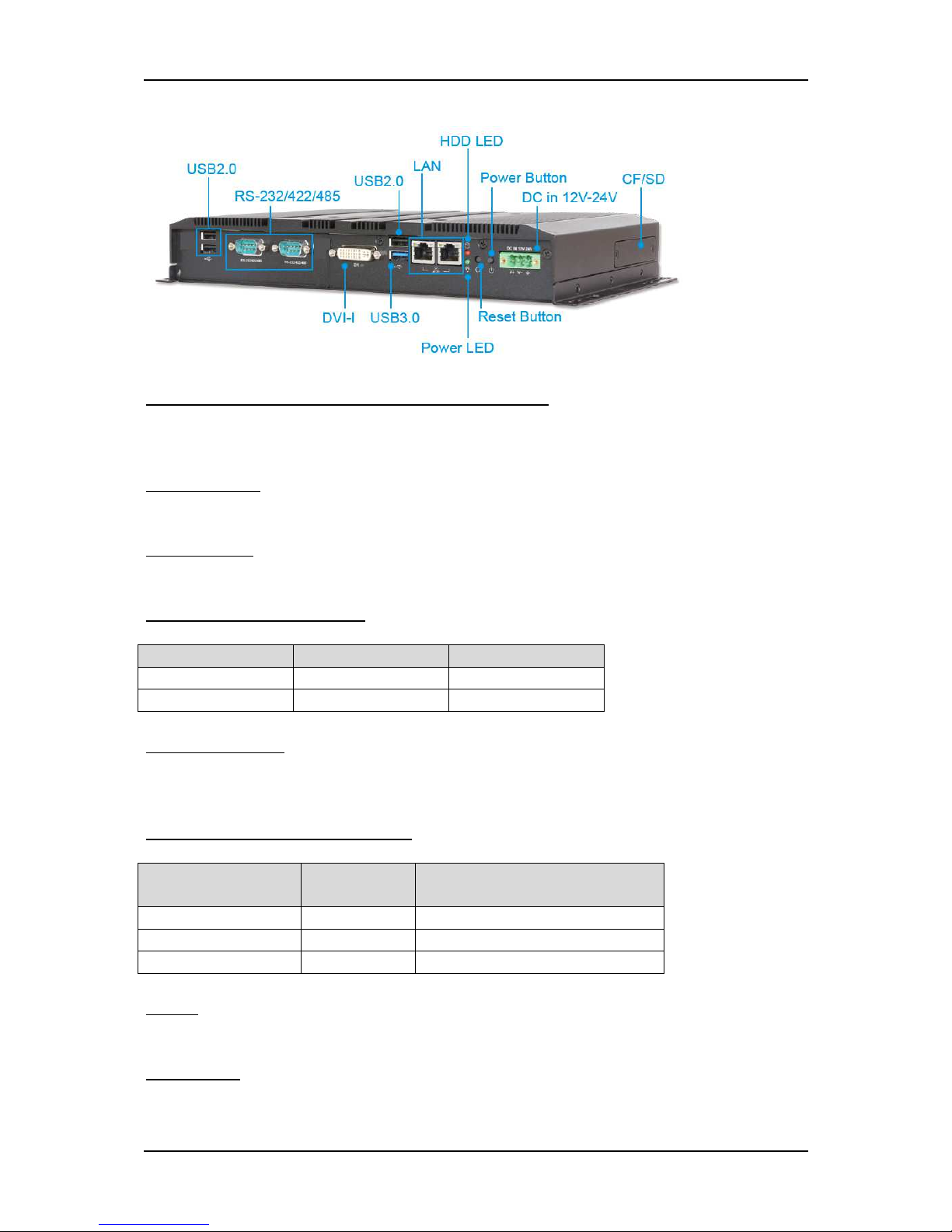
2.7.2 Rear View
DC in 12-24V via 3-pin Terminal Block Connector:
Provide power connection of Panel PC to the main power source via DC power cable
or AC/DC adapter.
Power Button:
Press the button to turn ON/OFF the system.
Reset Button:
Press the button to restart the system.
Power LED and HDD LED:
It demonstrates the power in and HDD working status of the system.
Status Power LED HDD LED
Off N/A N/A
Working Green Red
Gigabit Ethernet:
Two Gigabit Ethernet (10/100/1000 Mbits/sec) LAN ports by using dual Intel®
I210IT GbE Ethernet Controller (Support Jumbo Frame)
USB (Universal Serial Bus) ports:
Connectors for USB-compatible devices
With different I/O
kit combination…
Total # of
USB ports
Details
Default 4 3x USB 2.0 & 1x USB 3.0
Option 1 2 1x USB 2.0 & 1x USB 3.0
Option 2 4 3x USB 2.0 & 1x USB 3.0
DVI-I:
An external monitor can be provided via DVI-I interface.
COM ports:
Connectors for RS-232/422/485 connection

System Installation
WEBS-5491 Embedded System User’s Manual 2-10
*Note: The RS-232/422/485 configuration is determined by BIOS setting. Check BIOS
setting for details.
With different I/O
kit combination…
Total # of
COM ports
Details
Default 2 2x RS-232/422/485
Option 1 3 2x RS-232/422/485 & 1x RS-232
Option 2 1 1x RS-232/422/485
Line-out:
Connectors for audio line-out
With different I/O
kit combination…
Total # of
Audio ports
Details
Default 0 N/A
Option 1 0 N/A
Option 2 1 1x Line-out
CF Cover:
Remove the cover and install the CF card.
*Note: Refer to section 2.5 for installation guide.

BIOS Setup Information
WEBS-5491 Embedded System User’s Manual 3-1
Chapter 3
BIOS Setup Information
WEBS-5491 Series Panel PC adopts PEB-99A4 mother board. PEB-99A4 is
equipped with the AMI BIOS stored in Flash ROM. These BIOS has a built-in
Setup program that allows users to modify the basic system configuration easily.
This type of information is stored in CMOS RAM so that it is retained during
power-off periods. When system is turned on, PEB-99A4 communicates with
peripheral devices and checks its hardware resources against the configuration
information stored in the CMOS memory. If any error is detected, or the CMOS
parameters need to be initially defined, the diagnostic program will prompt the
user to enter the SETUP program. Some errors are significant enough to abort the
start up.
3.1 Entering Setup—Launch System Setup
Power on the computer and the system will start POST (Power On Self Test)
process. When the message below appears on the screen, press <Del> key will
enter BIOS setup screen.
Press <Del> to enter SETUP
If the message disappears before responding and still wish to enter Setup, please
restart the system by turning it OFF and On or pressing the RESET button. It can
be also restarted by pressing <Ctrl>, <Alt>, and <Delete> keys on keyboard
simultaneously.
Press <F1> to Run General Help or Resume
The BIOS setup program provides a General Help screen. The menu can be easily
called up from any menu by pressing <F1>. The Help screen lists all the possible
keys to use and the selections for the highlighted item. Press <Esc> to exit the
Help screen.

BIOS Setup Information
WEBS-5491 Embedded System User’s Manual 3-2
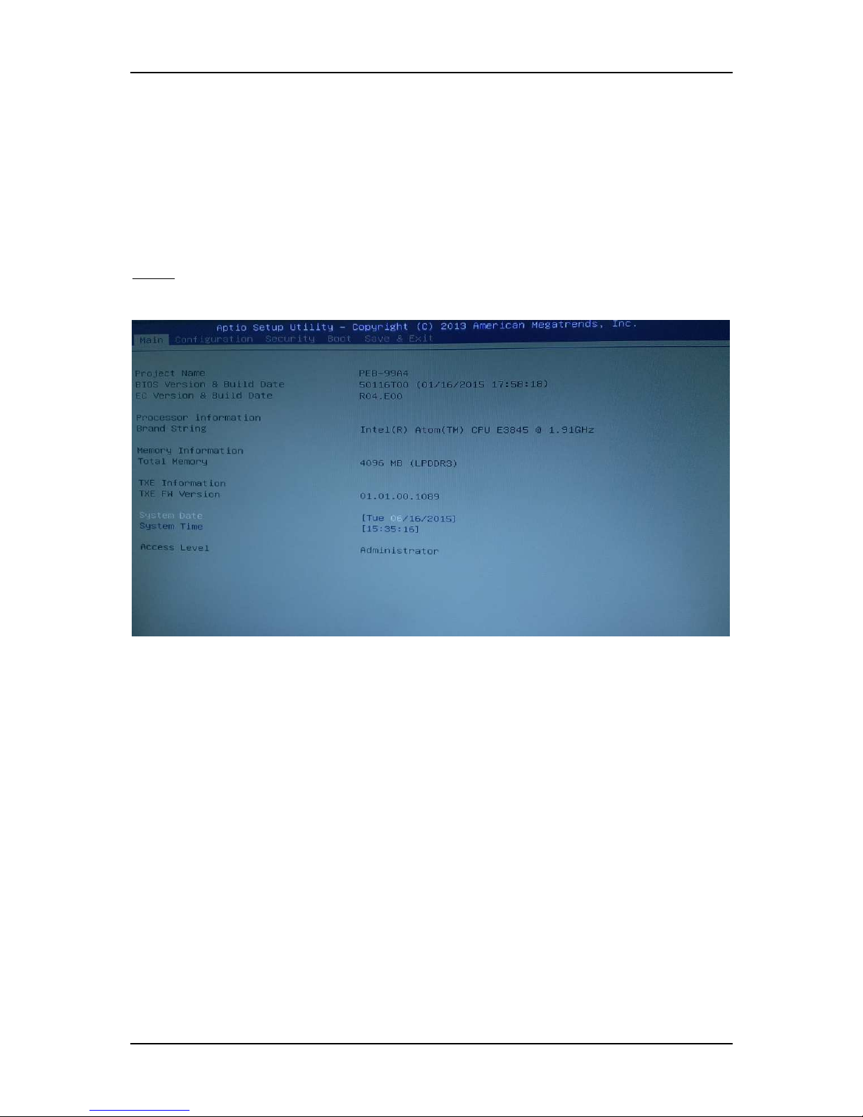
3.2 Main
Use this menu for basic system configurations, such as time, date etc.
BIOS Information, Memory Information
These items show the firmware and memory specifications of your system. Read
only.
System Date
The date format is <Day>, <Month> <Date> <Year>. Use [+] or [-] to configure
system Date.
System Time
The time format is <Hour> <Minute> <Second>. Use [+] or [-] to configure
system Time.

BIOS Setup Information
WEBS-5491 Embedded System User’s Manual 3-3
3.3 Configuration
Use this menu to set up the items of special enhanced features.
BIOS Setup Information
WEBS-5491 Embedded System User’s Manual 3-4
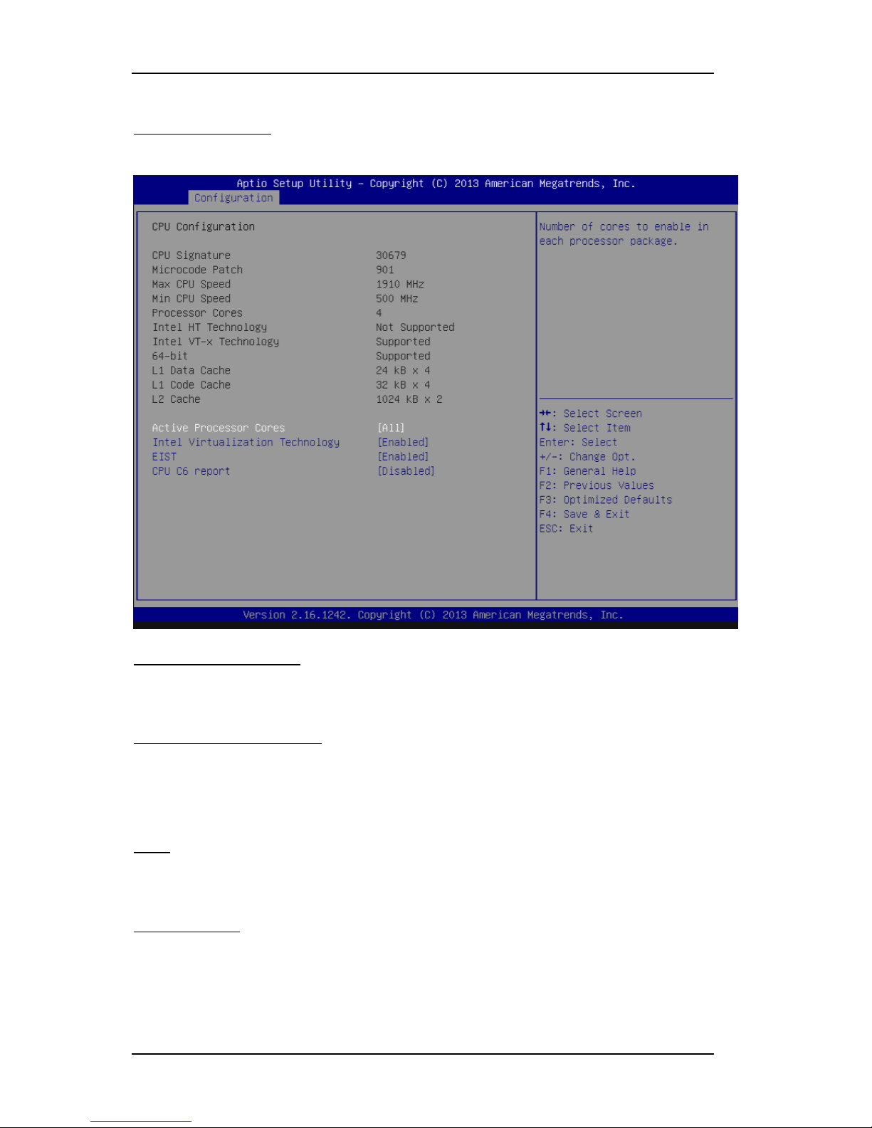
CPU configuration
CPU Configure the specific active core(s) and advanced processor management
technologies.
Active Processor Cores
Number of cores to enable in each processor package.
The choice: All( Default), 1.
Intel Virtualization Cores
When enabled, a VMM can utilize the additional hardware capabilities provided
by Vander pool Technology.
The choice: Disabled. Enabled(Default).
EIST
Enable/Disable Intel Speed Step.
The choice: Disabled. Enabled(Default).
CPU C6 report
Enable or Disable the CPU C6 (ACPI C3) report to OS.
The choice: Disabled(Default). Enabled.

BIOS Setup Information
WEBS-5491 Embedded System User’s Manual 3-5
Chipset Configuration
Configuration Chipset feature.
High Precision Timer
Enable or Disable the High Precision Event Timer.
The choice: Disabled. Enabled(Default).
Audio Controller
Control Detection of the Azalia device. Disabled = Azalia will be unconditionally
disabled. Enabled = Azalia will be unconditionally Enabled.
The choice: Disabled. Enabled(Default).
BIOS Setup Information
WEBS-5491 Embedded System User’s Manual 3-6
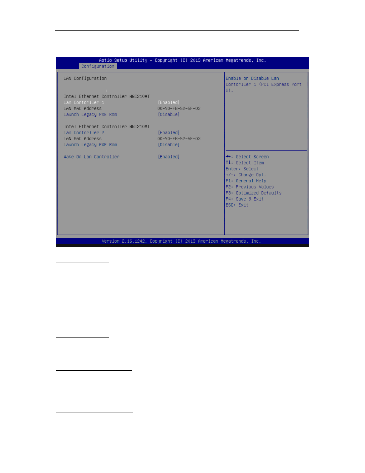
LAN Configuration
Configuration on board LAN device.
LAN Controller 1
Enable or Disable LAN Controller 1 (PCI Express Port 2).
The choice: Disabled. Enabled(Default).
Launch Legacy PXE Rom
Launch Legacy PXE Rom. [Disable] Not Launch Rom, [Enabled] Force Launch
Rom.
The choice: Disabled(Default). Enabled.
LAN Controller 2
Enable or Disable LAN Controller 2 (PCI Express Port 3).
The choice: Disabled. Enabled(Default).
Launch Legacy PXE Rom
Launch Legacy PXE Rom. [Disable] Not Launch Rom, [Enabled] Force Launch
Rom.
The choice: Disabled(Default). Enabled.
Wake on LAN Controller
Enable or Disable Intel LAN 0 and Intel LAN 1 WGI210AT wakeup function.
The choice: Disabled. Enabled(Default).

BIOS Setup Information
WEBS-5491 Embedded System User’s Manual 3-7
Graphic Configuration
Configure Graphics Setting.
GOP Driver
Enable GOP Driver will unload VBIOS; Disable it will load VBIOS
Choices: Enable(Default), Disable.
IGD Turbo Enable
Enable IGD Turbo Enable; Disable IGD Turbo Disable.
Choices: Enable(Default), Disable.
Primary Display
Select which of IGD/PCI Graphics device should be Primary Display.
Choices: Auto, IGD(Default), PCI, SG.
DVMT Pre-Allocated
Select DVMT 5.0 Pre-Allocated (Fixed) Graphics Memory sized used by the
Internal Graphic Device
Choices: 64M(Default), 96M, 128M, 160M, 192M, 224M, 256M, 288M, 320M, 352M,
384M,416M, 448M, 480M, 512M.

BIOS Setup Information
WEBS-5491 Embedded System User’s Manual 3-8
DVMT Total GFX Mem
Select DVMT 5.0 Total Graphics Memory sized used by the Internal Graphic
Device.
Choices: 128MB, 256MB(Default), Max.
Touch Pad
Touch Pad Enable/Disable.
Choices: Enable(Default), Disable.
LIGHT SENSOR
LIGHT SENSOR Support Enable/Disable..
Choices: Enable(Default), Disable.
Primary IGFX Boot Display
Select the Video Device which will be activated during POST. This as no effect if
external graphics present. Secondary will appear based on your Selection. VGA
modes will be supported only on primary display.
Choices: VBIOS Default(Default), DVI, LVDS.
Panel Scaling
Select the LCD Panel scaling option used by Internal Graphic device.
Choices: Auto(Default), Off, Force Scaling.
Backlight Control
Back Light Control Setting.
Choices: PWM Inverted, PWM Normal(Default), GMBus Inverted, GMBus
Normal.
Active LFP
Select the Active LEP Configuration. Mo LVDS: VBIOS does not enable LVDS.
eDP Port-A: LFP driven by Int-DisplayPort encoder from Port-A.
Choices: No LVDS, eDP Port-A(Default).
BIOS Setup Information
WEBS-5491 Embedded System User’s Manual 3-9
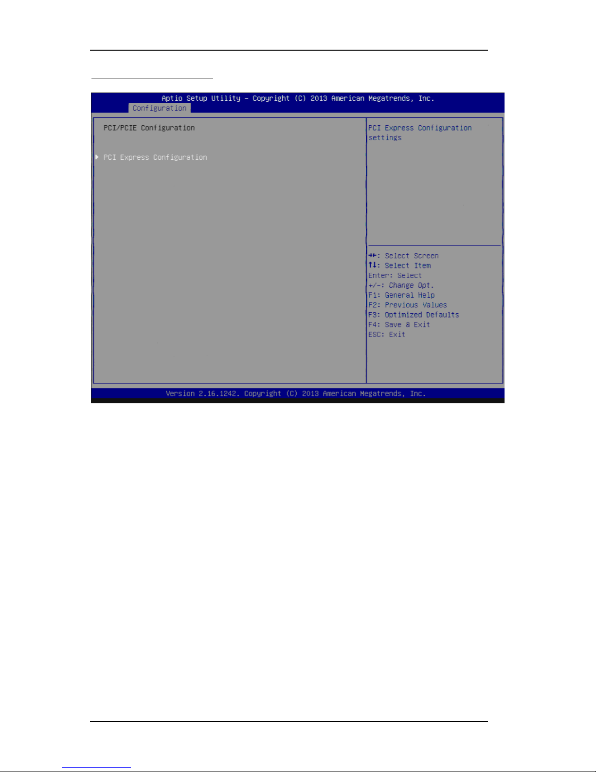
PCI/PCIE Configuration
PCI , PCI –X and PCI Express Setting.
BIOS Setup Information
WEBS-5491 Embedded System User’s Manual 3-10
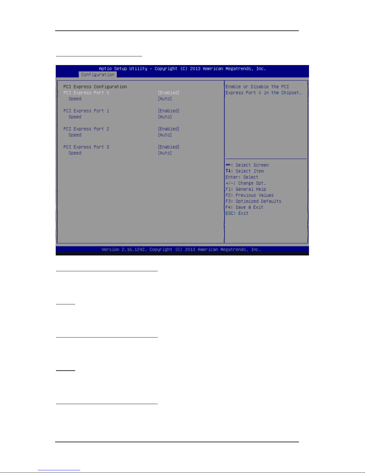
PCIE Express Configuration
PCI Express Configuration Setting.
PCI Express Configuration Port 0
Enable or Disable the PCI Express Port 0 in the Chipset.
Choices: Enable(Default), Disable.
Speed
Configuration PCIe Speed
Choices: Auto(Default), Gen1, Gen2.
PCI Express Configuration Port 1
Enable or Disable the PCI Express Port 1 in the Chipset.
Choices: Enable(Default), Disable.
Speed
Configuration PCIe Speed
Choices: Auto(Default), Gen1, Gen2.
PCI Express Configuration Port 2
Enable or Disable the PCI Express Port 2 in the Chipset.
Choices: Enable(Default), Disable.

BIOS Setup Information
WEBS-5491 Embedded System User’s Manual 3-11
Speed
Configuration PCIe Speed
Choices: Auto(Default), Gen1, Gen2.
PCI Express Configuration Port 3
Enable or Disable the PCI Express Port 3 in the Chipset.
Choices: Enable(Default), Disable.
Speed
Configuration PCIe Speed
Choices: Auto(Default), Gen1, Gen2.

BIOS Setup Information
WEBS-5491 Embedded System User’s Manual 3-12
SATA Configuration
SATA device Options setting.
Serial-ATA (SATA)
Enable or Disable Serial ATA.
Choices: Disabled, Enabled(Default).
SATA Mode
Select IDE / AHCI.
Choices: Disabled, IDE, AHCI(Default).
CF Device
Enabled / Disabled CF Device.
Choices: Disabled, Enabled(Default).
Serial-ATA Port 0
Enable or Disable Serial ATA Port 0.
Choices: Disabled, Enabled(Default).
BIOS Setup Information
WEBS-5491 Embedded System User’s Manual 3-13
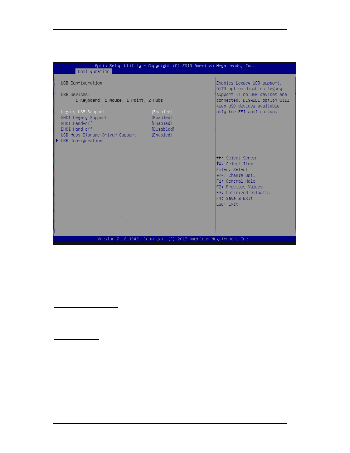
USB Configuration
USB Configuration Parameters.
Legacy USB Support
Enables Legacy USB support. AUTO option disables legacy support if no USB
devices are connected. DISABLE option will keep USB devices available only for
EFI applications.
Choices: Enabled, Disabled(Default).
XHCI Legacy Support
Enable/Disable XHCI Controller Legacy support.
Choices: Enabled, Disabled(Default).
XHCI Hand-off
This is a workaround for OSes without XHCI hand-off support. The XHCI
ownership change should be claimed by XHCI driver.
Choices: Enabled, Disabled(Default).
EHCI Hand-off
This is a workaround for OSes without EHCI hand-off support. The EHCI
ownership change should be claimed by EHCI driver.
Choices: Enabled, Disabled(Default).

BIOS Setup Information
WEBS-5491 Embedded System User’s Manual 3-14
USB Mass storage Driver Support
Enable/Disable USB Mass storage Driver Support.
Choices: Enabled(Default), Disabled.
USB Configuration
USB Configuration settings.
XHCI Mode
Mode of operation of XHCI controller
Choices: Smart Auto(Default), Auto, Enable, Disable.
USB2 Link Power Management
Enable/Disable USB2 Link Power Management.
Choices: Enable(Default), Disable.
USB 2.0 (EHCI) Support
Control the USB EHCI (USB2.0) functions. One EHCI controller must always be
enabled.
Choices: Enable, Disable(Default).
USB Port 0
Enable/Disable USB Port 0: USB 3.0 port on Board.
Choices: Enable(Default), Disable.

BIOS Setup Information
WEBS-5491 Embedded System User’s Manual 3-15
USB Port 1
Enable/Disable USB Port 1: USB 2.0 port on Board.
Choices: Enable(Default), Disable.
USB Port 2
Enable/Disable USB Port 2: The USB port turn into a mini PCIE.
Choices: Enable(Default), Disable.
USB Port 3
Enable/Disable USB Port 3: The USB port as USB HUB have 2 USB Port in
external cart.
Choices: Enable(Default), Disable.

BIOS Setup Information
WEBS-5491 Embedded System User’s Manual 3-16
Power Control Configuration
System Power Control Configuration Parameters.
Enable Hibernation
Enable or disable System ability to Hibernate (OS/S4 Sleep State). This option
may be not effective with some OS.
Choices: Disabled, Enabled(Default).
ACPI Sleep State
Select the highest ACPI sleep state the system will enter when the SUSPEND
button is pressed.
Choices: Suspend Disable, S3 (Suspend to RAM) (Default)
Restore AC Ring Loss
Select AC Power state when power is re-applied after a power failure.
Choices: Power Off, Power on, Last State(Default).
Wake on Ring Controller
Enable / Disable GPIO wake on Ring function.
Choices: Disabled(Default), Enabled.
Wake System from S5
Enable or Disable System wake on alarm event, Select Enable, system will wake
on the hr: mm: sec: specified.
Choices: Disabled(Default), Enabled.

BIOS Setup Information
WEBS-5491 Embedded System User’s Manual 3-17
Super IO Configuration
System Super IO Chip Parameters.
Serial Port
Enable or Disable Serial Port (COM) IO=3F8H; IRQ=4.
Choices: Disabled, Enabled(Default).
Interface
Set Current UART mode RS232, RS485, RS485/RS422.
Choices: RS232(Default), RS485 HALF DUFLEX, RS485/422 FULL DUFLEX.
Termination Control
Set Termination Control Disabled/ Enabled.
Choices: Disabled, Enabled(Default).
Direction Control
Set Direction Control set Enabled as Transceiver else; Disabled as Receiver.
Choices: Disabled(Default), Enabled.
Serial Port
Enable or Disable Serial Port (COM) IO=2F8H; IRQ=3.
Choices: Disabled, Enabled(Default).

BIOS Setup Information
WEBS-5491 Embedded System User’s Manual 3-18
Interface
Set Current UART mode RS232, RS485, RS485/RS422.
Choices: RS232(Default), RS485 HALF DUFLEX, RS485/422 FULL DUFLEX.
Termination Control
Set Termination Control Disabled/ Enabled.
Choices: Disabled, Enabled(Default).
Direction Control
Set Direction Control set Enabled as Transceiver else; Disabled as Receiver.
Choices: Disabled(Default), Enabled.
Serial Port
Enable or Disable Serial Port (COM) IO=240H; IRQ=10.
Choices: Disabled, Enabled(Default).
Serial Port
Enable or Disable Serial Port (COM) IO=248H; IRQ=11.
Choices: Disabled, Enabled(Default).
Watch Dog Timer
Enable or Disable Watch Dog Timer.
Choices: Disabled(Default), Enabled.
Timer Unit (Watch Dog Timer Enabled)
Select Timer count unit of WDT.
Choices: Seconds(Default), Minutes.
Timer value (Watch Dog Timer Enabled)
Set WDT Timer value Seconds/minutes.
Choices: Default [20].

BIOS Setup Information
WEBS-5491 Embedded System User’s Manual 3-19
Hardware Monitor
Monitor hardware status.

BIOS Setup Information
WEBS-5491 Embedded System User’s Manual 3-20
3.4 Security
Password Check Mode
[Setup] check password when enter setup screen, [Power On] check password on
every time system power on.
Choices: Setup(Default), Power On.
Administrator Password
Set Administrator Password
User Password
Set User Password.

BIOS Setup Information
WEBS-5491 Embedded System User’s Manual 3-21
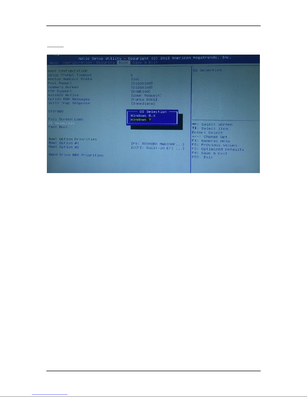
3.5 Boot
Use this menu to specify the priority of boot devices.
Setup Prompt Timeout
Number of seconds to wait for setup activation key. 65535 (0xFFFF) means
indefinite waiting.
Choices: Default [5].
Bootup NumLock state
Select the keyboard NumLock state.
Choices: On(Default), Off.
Post Report
Post Report Support Enabled/Disabled.
Choices: Disabled(Default), Enabled.
Summary Screen
Summary Screen Support Enabled/Disabled.
Choices: Disabled(Default), Enabled.

BIOS Setup Information
WEBS-5491 Embedded System User’s Manual 3-22
CSM Support
Enabled/Disabled CSM Support.
Choices: Disabled, Enabled(Default).
GateA20 Active
UPON REQUEST – GA20 can be disabled using BIOS services. ALWAYS – do not
allow disabling GA20; this option is useful when any RT code is executed above
1MB.
Choices: Upon Request(Default), Always.
Option ROM Messages
Set display mode for Option ROM.
Choices: Force BIOS(Default), Keep Current.
INT19 Trap Response
BIOS reaction on INT19 trapping by Option ROM: IMMEDIATE – execute the
trap right away; POSTPONED – execute the trap during legacy boot.
Choices: Immediate(Default), Postponed.
Storage
Controls the of execution of UEFI and Legacy Storage OpROM.
Choices: Do not launch(Default), UEFI only, Legacy only.
Full Screen Logo
Enables or Disables Quiet Boot option and Full screen Logo.
Choices: Disabled(Default), Enabled.
OS Selection
OS Selection
Choices: Windows 8.X(Default), Windows 7.
Fast Boot
Enables or Disables boot with initialization of a minimal set of devices required to
launch active boot option. Has no effect for BBS boot options.
Choices: Disable(Default), Enabled.
Boot Option #1
Sets the system boot order
Choices: UEFI: Built-in EFI Shell, Disabled.

BIOS Setup Information
WEBS-5491 Embedded System User’s Manual 3-23
3.6 Save and Exit
Save Changes and Reset
Reset the system after saving the changes.
Pressing <Enter> on this item asks for confirmation: Save configuration and reset.

BIOS Setup Information
WEBS-5491 Embedded System User’s Manual 3-24
Discard Changes and Exit
Reset system setup without saving any changes.
Pressing <Enter> on this item asks for confirmation: Reset without saving.
Restore Defaults
Restore/Load Default values for all the setup options.
Pressing <Enter> on this item asks for confirmation: Load Optimized Default.

Important Instructions
WEBS-5491 Embedded System User’s Manual 4-1
Chapter 4
Important Instructions
This chapter includes instructions which must be carefully followed when the
fan-less embedded system is used.
4.1 Note on the Warranty
Due to their limited service life, parts which, by their nature, are especially subject to
wear are not included in the guarantee beyond the legal stipulations.
4.2 Exclusion of Accident Liability Obligation
Portwell, Inc. shall be exempt from the statutory accident liability obligation if users
fail to abide by the safety instructions.
4.3 Liability Limitations / Exemption from the Warranty Obligation
In the event of damage to the system unit caused by failure to abide by the hints in
this manual and on the unit (especially the safety instructions), Portwell, Inc. shall
not be required to respect the warranty even during the warranty period and shall
be free from the statutory accident liability obligation.
4.4 Declaration of Conformity
EMC
CE/FCC Class A
This equipment complies with Part 15 of the FCC Rules. Operation is subject to the
following two conditions:
1. This equipment may not cause harmful interference.
2. This equipment must accept any interference that may cause undesired operation.
Applicable Standards:
EN 55022: 2006 + A1: 2007, Class A
EN 61000-3-2: 2006
EN 61000-3-3: 1995 + A1: 2001 + A2: 2005
EN 55024: 1998 + A1: 2001 + A2: 2003
IEC 61000-4-2: 2008
IEC 61000-4-3: 2006 + A1: 2007
IEC 61000-4-4: 2004
IEC 61000-4-5: 2005
IEC 61000-4-6: 2007
IEC 61000-4-8: 1993 + A1: 2000
IEC 61000-4-11: 2004
FCC 47 CFR Part 15 Subpart
Frequent Asked Questions
WEBS-5491 Embedded System User’s Manual 5-1
Chapter 5
Frequent Asked Questions
Q1: How to set OS Selection for different OS?
Answer:
You can find OS Selection under BIOS setting.
Step1. Power on the computer and the system will start POST (Power on Self Test)
process. When the message appears on the screen, press <Del> key and enter BIOS
setup screen.
Frequent Asked Questions
WEBS-5491 Embedded System User’s Manual 5-2
Step2. In page “Boot”, you can find OS Selection and choose the corresponding OS.
Note: For Linux OS, please choose Windows 7.

Frequent Asked Questions
WEBS-5491 Embedded System User’s Manual 5-3
Q2: What supposed to do when forget the password of system BIOS?
Answer:
Please turn off the power supply, and then find the JP1 to set it from 1-2 short to 2-3
short. Wait for 5 seconds to clean password; then set it back to 1-2 short to turn on
power supply.
JP1: CMOS Setup
PIN NO. DESCRIPTION
1-2
Normal (Keep CMOS Setup) ★ Default
2-3 Clear CMOS Setup
Q3: How to set AT mode for the system?
Answer:
The default setting is ATX mode: user needs to press the power button in order to
turn on the system. By adjusting SW2 port 1 jumper on board and restart the system,
user can set the system as AT mode.
SW2: AT/ATX & BIOS recovery Setup
PIN NO. DESCRIPTION
1-4(Port1)
ON: AT Mode
OFF:ATX Mode ★ Default
*Note: Diagram ATX mode setting
*Note: Diagram AT mode setting
 Loading...