


1/26
:$'(
Intel® Core™ i7/i5/i3 mobile Processor
QM67 Mini ITX Mother Board
User’s Manual
Rev. 0.0
2011/04/27

:$'( User’s Manual
2 / 26
Copyright
All rights reserved. The information contained in this guide has been v alidated and
reviewed f or accuracy. No patent liability is assumed with respect to the use of th e
information contained herein. While every prec aution has been taken in the preparation of
this guide, the Manufacturer assumes no responsibility for errors or omissions.
No part of this publication may be reproduced, stored in a retrieval system, or transmitted in
any form or by any means, el ectronic, mechanical, photocopying, recording, or otherwise,
without the prior written permission of Manufacturer.
Trademark
Intel
®
Core™, Pentium® and Celeron® are registered trademarks of Intel® Corporation.
Microsoft
®
and Windows® are registered trademarks of Microsoft Corporation.
All products and company na mes are trademarks or regist ered trademarks of their
respective holders.
These specifications are subject to change without notice.
Technical Support
We hope you to get the maximum performance fr om your products and be willing to help if
running into technical difficulties. For the mo st frequently asked questions, it’s easily foun d
answers from the product documentation and usua lly a lot more detailed, so please t ake
reference to this manual first. If the answer still can not be found, gather all the information
or questions applying to the problem, and with the product on hand, contact your distributor,
sales representative, or cust omer service center for tec hnical support. Most problems
reported are minor and able to be easily solv ed over the phone. In addition, free technic al
support is available and alwa ys ready to give advic es on application requirements or
specific information on the installation and operation of any of our products.
Please have the following information ready before you call:
1. Product name and serial number
2. Description of your peripheral attachments
3. Description of your software (operating system, version, application software, etc.)
4. A complete description of the problem
5. The exact wording of any error messages

:$'(User’s Manual
3 / 26
How to Use This Manual
This manual is written for the system integr ator, PC technician and knowledgeable PC end
user. It describes how to configure your :$'( to meet various operating requirements.
The user ’s manual is divided int o three c hapters, with each chapter addressing a b asic
concept and operation of the server board.
Chapter 1: Introduction - It gives you an overview of the product specifications and basic
system architecture for the motherboard.
Chapter 2: Hardw are Configuration Setting - Shows the definitions and locations of
Jumpers and Connectors so that you can easily configure your system.
Chapter 3: System Installation - Describes how to properly mount the CPU, Main memory,
for a safe installation.

:$'( User’s Manual
4 / 26
Table of Content
CHAPTER 1 ........................................................................................................................ 5
1. Introduction ................................................................................................................. 6
1.1 Description ........................................................................................................... 6
1.2 Dimensions .......................................................................................................... 9
CHAPTER 2 ...................................................................................................................... 10
2. Hardware Configuration Setting .............................................................................. 11
2.1 Board Layout ..................................................................................................... 12
2.2 Jumpers & Connectors ..................................................................................... 13
2.3 Jumpers & Connectors setting ........................................................................ 14
CHAPTER 3 ...................................................................................................................... 19
3. System Installation ................................................................................................... 20
3.1 Main Memory ...................................................................................................... 20
3.2 Installations the motherboard .......................................................................... 21
Appendix .......................................................................................................................... 22
Appendix A: WDT Programming Guide ......................................................................... 23

ADE-6065 User’s Manual
5 / 26
CHAPTER 1

:$'( User’s Manual
6 / 26
1. Introduction
1.1 Description
Taking adv antages of Intel energy-ef ficient processing, :$'( Mini-ITX motherboard
adopts 2nd Generation Intel® Core™ processor family and Intel® QM67 chip set to fit th e
high performance computer system applic ations for meeting today’s demanding p ace and
keep complete comp atibility with hardware and software designed. The onboard devic e
support one PCI Expr ess x16 for an alternativ e graphics add-on card. Except building in
Intel® 82579LM Gigabit Ethernet PHY for AMT 7.0 function, Realtek RTL8111DL Gigabit
Ethernet controller offers a stable high-speed networking function.
:$'(comes with theInte l
®
HD Graphics 2000/3000 and supporting Intel vPro
technology. The board also features two SO -DIMM sockets up to 8 GB SDRAM with dual
channel DDR3 1066/1333, four Serial ATA: two data transferring at up to 3 Gb/s, two da ta
transferring at up to 6 Gb/s; eight hi-speed USB 2.0 port s, optional Intel® Trusted Platform
Module 1.2, and HDA through ID T IDT92HD87 audio codec. The onboar d ITE I T8781 I/O
Controller support s four serial port s: two RS -232 serial port s by ex ternal I/O connectors,
two RS-232 pin headers; Pin 9 Select for 5V/12V /RI. Hardware Monitor function, two 6-pin
Mini-DIN c onnectors for PS/2 mouse and ke yboard, besides , a build-in feature of
monitoring CPU, system te mperature and cooling fan st atus will also provide user more
security and stability.
With these impressive functions, :$'(Mini-ITX motherboard is an ideal solution for
POS, multi-media, gaming, DVR, KIOSK, medical equipm ent, industrial automation,
financial automation, proce ss control, semiconductor equi pment, and network security
markets.

:$'( User’s Manual
7 / 26
Specifications WADE-8110
M/B
CPU
Intel
®
Sandy Bridge – MB , rPGA.type
Intel® Core™ i7-2710QE processors (2.1GHz, 45W)
Intel® Core™ i5-2510E processors (2.5GHz, 35W)
Intel® Core™ i3-2330E processors (2.2GHz, 35W)
Intel® Celeron B810 processors (1.6GHz, 35W)
BIOS AMI UEFI BIOS with 64 Mb SPI Flash ROM support AMT7.0
System Chipset Intel QM67 (Cougar Point – MB)
I/O Control ITE 8781F
System Memory
2 x 200-pin SO-DIMM socket , support DDR3 1066/1333 SDRAM
Max. up to 8 GB memory
Storage 2 x SATA 3.0 , 2 x SATA 2.0 and one optional for SATA DOM (SATA3)
Watchdog Timer Reset; 1 sec.~255 min. and 1 sec. or 1 min./step
H/W Status Monitor Monitoring CPU , system temperature, and voltage status
TPM INFINEON , SLB9635TT1.2
ACPI Mode S0, S1, S3, S4, S5
Expansion 1 x PCI-E *16
Display
Graphics Controller Intel® Sandy Bridge Integrated
Display Interface Dual displays by VGA & LVDS , VGA & DVI or DVI & LVDS
Ethernet
Controller Intel
®
82579LM 10/100/1000 Gigabit Ethernet Controller with AMT7.0
Realtek RTL8111DL Gigabit Ethernet Controller
Interface/connector
IEEE 802.3 10BASE-T / 100BASE-TX / 1000BASE-T compliant,
Support Wake On LAN
2 x RJ-45 rear panel connector with two LEDs indicators
Audio
HDAC IDT
IDT92HD87 High Definition audio codec
On-board Header MIC, Line-out & Speaker with 2W + 2W amplifier
External I/O ( Rear I/O )
Gigabit-LAN
2 x RJ-45 LAN Port
Act/Link LED, Speed LED 10-Off / 100-Green / 1000-Yellow
USB 4 x USB
DVI-D 1 x D-SUB 24-pin
VGA 1 x D-SUB 15-pin
COM
2 x RS-232 D-SUB 9-Pin Ports for COM1~COM2
Pin 9 Selection for 5V/12V/RI , 5V & 12V ( Max. : 1A output with Fuse )

WADE-8110 User’s Manual
8 / 26
Audio 3 x Audio Jacks for Line-out, MIC-input, Line-input
PS/2 2 x Mini-DIN 6-pin Keyboard & Mouse
Internal I/O
SATA 4 x ( 1 x 7 ) SATA connector
LVDS 1 x ( 2 x 20 ) 1.25mm pin-header for 24-bit with brightness control
COM
2 x ( 2 x 5 ) 2.54mm pin-header for COM3 & 4
Pin 9 Select for 5V/12V/RI
5V & 12V ( Max. : 1A output with Fuse )
USB 2 x ( 2 x 5 ) 2.54mm pin-header for USB5~8
Audio 1 x ( 1 x 4 ) 2.0mm pin-header for Speaker with 2W + 2W amplifier
Internal Header
Front Panel 1 x ( 2 x 5 ) 2.54mm pin header
SATA Power 4 x ( 1 x 4 ) 2.54mm pin header for 5V/12V output (HDD Power)
SATA DOM jumper 1 x ( 1 x 3 ) 2.0mm pin header (1:5V, 2:Pin7, 3:GND)
DC In 1 x ( 2 x 2 ) connector ( DC 19V ~ 24V input )
Inverter 1 x ( 1 x 5 ) 2.0mm pin-header
CPU Fan 1 x ( 1 x 4 ) 2.54mm pin-header with PWM smart Fan function
System Fan 1 x ( 1 x 3 ) 2.0 mm pin-header
Clear CMOS 1 x ( 1 x 3 ) 2.54mm pin-header
Powered Com Pin 9 4 x ( 2 x 3 ) 2.0 mm pin-header ; ( 1: 5V , 3: 12V , 5: RI ; 2,4,6: Pin9 )
Certification
EMC Compliance Meets EN55022, EN55024 and CE / FCC Class A standard
OS Support Win-7,Vista, Win-XP, WinXPE, DOS,Linux, Win-7 Embedded
Environments
Compliance RoHS , WEEE
Operating Temperature 0°C~60°C
Storage Temperature 0°C~70°C
Operating Humidity 5%~90% relative humidity, no condensing
Size (L x W) 170mm x 170mm

WADE-8110 User’s Manual
9 / 26
1.2 Dimensions

ADE-6065 User’s Manual
10 / 26
CHAPTER 2

WADE-8110 User’s Manual
11 / 26
2. Hardware Configuration Setting
This chapter gives the definitions and show s the positions of jumpers, headers and
connectors. All of the configuration jumpers on the board are in the proper position. T he
default settings shipped from factory are marked with an asterisk ().
In general, jumpers on the board are used to se lect options for cert ain features. Some of
the jumpers are designed to be user-configur able, allowing for system enhancement. The
others are for testing purpose onl y and should not be altered. T o select any option, cover
the jumper cap over (SHOR T) or remove (NC) it fro m the ju mper pins according to the
following instructions. Here, NC stands for “Not Connect”.

WADE-8110 User’s Manual
12 / 26
2.1 Board Layout

WADE-8110 User’s Manual
13 / 26
2.2 Jumpers & Connectors
JUMPERS FUNCTION REMARK
AMT1
PLL Odvr Voltage 1 x 3 header
A_ON1
Auto Power On Setting 1 x 3 header
JCLR1
Clear CMOS 1 x 3 header
JCLR2
Reset & Isolation Bypass 1 x 3 header
JCOMA
COM1 Pin9 Setting 2 x 3 header
JCOMB
COM2 Pin9 Setting 2 x 3 header
JCOMC
COM3 Pin9 Setting 2 x 3 header
JCOMD
COM4 Pin9 Setting 2 x 3 header
JLCD1
LCD Voltage Setting 1 x 3 header
SDOM1
SATA3 Pin7 Setting 1 x 3 header
CONNECTORS FUNCTION REMARK
CPUFAN1
CPU FAN connector 1 x 4 wafer
SYSFAN1
System FAN connector 1 x 3 wafer
PANEL1
PANEL connector 2 x 5 header
USB1
USB connector 2 x 5 header
USB2
USB connector 2 x 5 header
AMP_OUT1
Speaker connector 1 x 4 wafer
COM3
RS-232 2 x 5 box header
COM4
RS-232 2 x 5 box header
LPC1
Port 80 connector 2 x 5 headers
INVERT1
Inverter connector 1 x 5 wafer
SATA_PWR1
SATA power connector 1 x 4 wafer
SATA_PWR2
SATA power connector 1 x 4 wafer
SATA_PWR3
SATA power connector 1 x 4 wafer
SATA_PWR4
SATA power connector 1 x 4 wafer
DC_IN1
DC in power connector (19V ~ 24V) 2 x 2 connector
LVDS1
LVDS connector 2 x 20 connector
SATA0
SATA 3.0 Connector
SATA1
SATA 3.0 Connector
SATA2
SATA 2.0 Connector
SATA3
SATA 2.0 Connector

WADE-8110 User’s Manual
14 / 26
2.3 Jumpers & Connectors setting
2.3.1 AMT1
PIN No. Description
1 -2 Debug Mode
2-3 Normal
2.3.2 A_ON1
PIN No. Description
1-2 Enable
2-3 Disable
2.3.3 JCLR1
PIN No. Description
1-2 Clear CMOS
2-3 Keep CMOS
2.3.4 JCLR2
PIN No. Description
1-2 Secondary RTC Reset
2-3 Normal
2.3.5 JCOMA, JCOMB, JCOMC, JCOMD
PIN No. Description
1-2 5V
3-4 12V
5-6 RI
3 2 1
2 6
1 5
1 2
5 6
3 2 1
3 2 1
3 2 1
WADE-8110 User’s Manual
15 / 26
2.3.6 JLCD1
PIN No. Description
1-2 5V
2-3 3.3V
2.3.7 SDOM1
PIN No. Description
1-2 5V
2-3 GND
2.3.8 CPUFAN1 (Wafer 4*1, 2.54mm, 1-Wall)
PIN No. Description
1
FAN speed control
2
FAN speed sense
3
+12V
4
GND
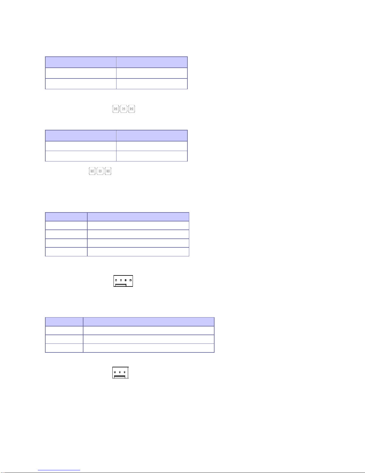
2.3.9 SYSFAN1 (Wafer 3*1, 2.54mm, 1-Wall)
PIN No. Description
1
GND
2
+12V
3
FAN speed sense
3 1
4 1
1 3
3 2 1

WADE-8110 User’s Manual
16 / 26
2.3.10 PANEL1 (Pin Header, 5*2 2.54mm, pin10 empty)
2.3.11 USB1, USB2 (Pin Header, 5*2 2.54mm, pin9 empty)
2.3.12 AMP_OUT1 (Wafer, 4*1 2.0mm)
PIN No. Description PIN No. Description
1 HD LED+ 2 Power LED+
3 HD LED- 4 Power LED-
5 GND 6 Power Button
7 Re set Button 8 GND
9 NC
PIN No. Description PIN No. Description
1 5V Dual 2 5V Dual
3 USB1 - 4 USB2 -
5 USB1 + 6 USB2 +
7 GND 8 GND
9 10 GND/Shield
PIN No. Description
1 SPK _R+
2 SPK _R-
3 SPK _L+
4 SPK _L-
2 8
1 9
2 10
1 7
1 4

WADE-8110 User’s Manual
17 / 26
2.3.13 COM3, COM4 (BOX HEADER, 5*2, 2.54mm,LF)
2.3.14 LPC1 (Pin Header, 5*2, 2.54mm)
2.3.15 INVERT1 (Wafer, 5*1 2.0mm)
PIN No. Description PIN No. Description
1 COM portA DCD# 2 COM portA DSR#
3 COM portA RXD# 4 COM portA RTS#
5 COM portA TXD# 6 COM portA CTS#
7 COM portA DTR# 8 COM portA RI#
9 GND 10 GND
PIN No. Description PIN No. Description
1 CLK _LPC 2 LPC AD1
3 PL TRST 4 LPC AD0
5 LPC FRAME 6 VCC3
7 LPC AD3 8 GND
9 LPC AD2 10 GND
PIN No. Description
1 +12V
2 GND
3 LCD _BKL
4 L _BKLT_CTRL
5 GND
2 10
1 9
10 9
2 1
2 10
1 9
1 5
WADE-8110 User’s Manual
18 / 26
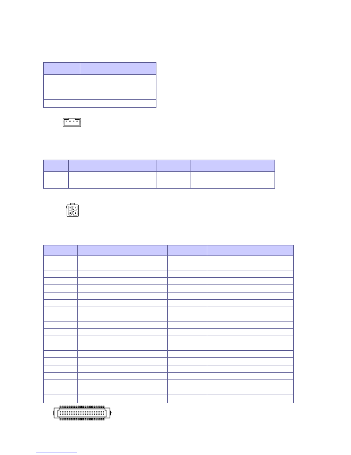
2.3.16 SATA_PWR1 ~ 4 (Wafer, 4*1 2.0mm)
2.3.17 DC_IN1 (Power connector, 2*2)
2.3.18 LVDS1 (Housing Header, 20*2)
PIN No. Description
1 +12V
2 GND
3 GND
4 VCC5
PIN No. Description PIN No. Description
1 GN D 3 DCIN (19V ~24V)
2 GN D 4 DCIN (19V ~24V)
PIN No. Description PIN No. Description
1 NC 2 NC
3 GND 4 GND
5 LVDSA D ATA0N 6 LVD SA DATA 1N
7 LVDSA DATA0P 8 LVDS A DATA1P
9 GND 10 GND
11 LVD SA DATA 2N 12 LVDS A CLKN
13 LVD SA DATA 2P 14 LV DSA C L KP
15 GND 16 GND
17 LVD SA DATA3N 18 LV DSB DATA 0N
19 LVD SA DATA 3P 20 LVDSB D ATA0P
21 GND 22 GND
23 LVD SB DATA1N 24 LV DSB DATA2N
25 LVD SB DATA 1P 26 LVDSB D ATA2P
27 GND 28 GND
29 LVDSB C LKN 30 LVDSB D ATA3N
31 LV D SB CLK P 32 LV DSB DATA 3P
33 NC 34 GND
35 LV DS DDC C LK 36 GND
37 LVD S DDC D ATA 38 LCD Voltage
39 VCC_LCD 40 LCD_Voltage
1 4
3 4
2 1
2 40

WADE-8110 User’s Manual
19 / 26
CHAPTER 3

WADE-8110 User’s Manual
20 / 26
3. System Installation
This chapter provides you with the instructions on how to install memory and how to setup
your system.
3.1 Main Memory
The figures display the notch marks and what they should look like on your SO-DIMM
memory module.
SO-DIMM DDR3 has 204-pin and two notches which match the onboard SO-DIM M
socket. Refer to WADE-8110 for memory specific details.
Handle your new memory module carefully ; do not flex or bend it. Always grasp the
module by its edges.
Memory module and the exp ansion socket are keyed. A small plastic bridge in the
socket must align with those three notches in the module. The keyed bridge and notch
insures that the module can be plugged into the socket into the socket one way only.
Insert memory module at 30 °angle. Make sure the notch and module are proper
aligned.
Once the module is properly aligned with the socket, rot ate the module downwards
until the clips at each end of expansion click into place. To remove socket and pressing
straight down until it fits tightly into the SO-DIMM socket.
SO-DIMM Memory and 204-pin Socket
Memory Installation
Notch
Notch
Notch
Memory module
SO-DIMM socket

WADE-8110 User’s Manual
21 / 26
NOTE: For maintaining system stability, do not change any of memory parameters in BIOS
setup to upgrade your system performance without acquiring technical information.
3.2 Installations the motherboard
To install the board into standard chassis or proprietary environment, you need to perform
the following steps:
1. Check all jumpers setting on proper position
2. Install and configure memory module on right position
3. Place the board into the dedicated position in your system
4. Connect cables to existing peripheral devices and secure it
WARNING: Please ensure that your motherboard properly inserted and fixed by
mechanism. Otherwise, the system might be unstable or do not work from bad contact.

WADE-8110 User’s Manual
22 / 26
Appendix

WADE-8110 User’s Manual
23 / 26
Appendix A: WDT Programming Guide
Watch Dog Timer
- Time resolution 1 minute or 1 second, maximum 65535 minutes or 65535 seconds
- Output to KRST# when expired
Base Address
Two PNP I/O port addresses used for Watch Dog Timer accessing
2Eh: EFIR (Extended Function Index Register, for identifying CR index number)
2Fh: EFDR (Extended Function Data Register, for accessing desired CR)
WDT Control Timer 1, 2, 3 Control Register
Bit Description
7 WDT Timeout Enable (WTE)
1 : Disable
0 : Enable
6 WDT Reset upon Mouse Interrupt (WRKMI)
1 : Disable
0 : Enable
5 WDT Reset upon Keyboard Interrupt (WRKBI)
1 : Disable
0 : Enable
4 Reserved
3-2 Reserved
1 Force Time-out (FTO)
This bit is self-clearing
0 WDT Status (WS)
1 : WDT value reaches 0
0 : WDT value is not 0
Register Location: LDN=07h Index=71h
Attribute: Read/Write
Size: 8bit

WADE-8110 User’s Manual
24 / 26
WDT Control Timer Configuration Register
Bit Description
7 WDT Time-out Value Select 1
1 : Second
0 : Minute
6 WDT Output through KRST (Pulse) Enable (WOKE)
1 : Enable
0 : Disable
5 WDT Time-out value Extra select (WTVES)
1 : 64 ms x WDT Timer-out value (default = 4s)
0 : Determined by WDT Time-out value select 1 (bit 7 of this register).
4 WDT Output through PWROK (Pulse) Enable (WOPE)
1 : Enable
0 : Disable
During LRESET#, this bit is selected by JP7 power-on strapping option
3-0 Select interrupt level Note1 for WDT (SIL)
Note 1 :
Interrupt level mapping
Fh – Dh : not valid
Ch : IRQ12
3h : IRQ3
2h : not valid
1h : IRQ1
0h : no interrupt mapping
WDT Control Timer Time-Out Value (LSB) Register
Bit Description
7-0 WDT Time-out Value 7-0 (WTV)
Register Location: LDN=07h Index=72h
Attribute: Read/Write
Size: 8bit
Register Location: LDN=07h Index=73h
Attribute: Read/Write
Size: 8bit

WADE-8110 User’s Manual
25 / 26
WDT Control Timer Time-Out Value (MSB) Register
Bit Description
7-0 WDT Time-out Value 15-8 (WTV)
Code Example :
#define WDT_IDX 0x2E
#define WDT_DAT 0x2F
// 1. Enter MB PNP mode
//
outportb(WDT_IDX, 0x87);
outportb(WDT_IDX, 0x01);
outportb(WDT_IDX, 0x55);
outportb(WDT_IDX, 0x55);
outportb(WDT_IDX, 0x07); // Select logic device 7
outportb(WDT_DAT, 0x07);
// 2. Set watch dog timeout value
//
outportb(WDT_IDX, 0x73) ; // Watch dog timer time-out value (LSB)
outportb(WDT_DAT, 0x1E); // Setup 30 seconds time-out value
outportb(WDT_IDX, 0x74) ; // Watch dog timer time-out value (MSB)
outportb(WDT_DAT, 0x00);
// 3. Enable watch dog timer
//
outportb(WDT_IDX, 0x71); // Watch dog control register
outportb(WDT_DAT, 0xF0);
outportb(WDT_IDX, 0x72); // Watch dog timer configuration register
outportb(WDT_DAT, 0xC0); // Watch dog enable
// 4. Disable watch dog timer
//
outportb(WDT_IDX, 0x73) ; // Watch dog timer time-out value (LSB)
outportb(WDT_DAT, 0x00);
outportb(WDT_IDX, 0x74) ; // Watch dog timer time-out value (MSB)
Register Location: LDN=07h Index=74h
Attribute: Read/Write
Size: 8bit

WADE-8110 User’s Manual
26 / 26
outportb(WDT_DAT, 0x00);
outportb(WDT_IDX, 0x71); // Watch dog control register
outportb(WDT_DAT, 0x00);
outportb(WDT_IDX, 0x72); // Watch dog timer configuration register
outportb(WDT_DAT, 0x00);
// 5. Leave MB PNP mode
//
outportb(WDT_IDX, 0x02); // Exit
outportb(WDT_DAT, 0x02);
 Loading...