

Page 1

www.ipc2u.ru www.ipc2u.de www.sovio.com Date: 01/07/2016
RUBY-9719VG2AR
Industrial Mainboard
User's Manual
Version 1.0
Copyright © Portwell, Inc., 2009. All rights reserved.
All other brand names are registered trademarks of their respective owners.
Page 2

Preface
www.ipc2u.ru www.ipc2u.de www.sovio.com Date: 01/07/2016
Table of Contents
How to Use This Manual
Chapter 1 System Overview.......................................................................................................1-1
1.1 Introduction.................................................................................................................................. 1-1
1.2 Check List ..................................................................................................................................... 1-2
1.3 Product Specification ..................................................................................................................1-2
1.3.1 Mechanical Drawing......................................................................................................... 1-5
1.4 System Architecture .................................................................................................................... 1-6
Chapter 2 Hardware Configuration ...........................................................................................2-1
2.1 Jumper Setting ............................................................................................................................. 2-1
2.2 Connector Allocation .................................................................................................................. 2-2
Chapter 3 System Installation....................................................................................................3-1
3.1 Intel LGA 775 Processor .............................................................................................................3-1
3.2 Main Memory .............................................................................................................................. 3-4
3.3 Installing the Single Board Computer ...................................................................................... 3-5
3.3.1 Chipset Component Driver.............................................................................................. 3-5
3.3.2 Intel Integrated Graphics GMCH Chip.......................................................................... 3-5
3.3.3 On-board Fast Ethernet Controllers................................................................................ 3-6
3.3.4 On-board High Definition Audio Controller ................................................................3-6
3.3.5 Intel Matrix Storage Manager Device............................................................................. 3-6
3.4 Clear CMOS Operation............................................................................................................... 3-8
3.5 WDT Programming Guide.........................................................................................................3-8
3.6 GPIO Programming Guide ......................................................................................................3-10
Chapter 4 BIOS Setup Information............................................................................................4-1
4.1 Entering Setup -- Launch System Setup................................................................................... 4-1
4.2 Main............................................................................................................................................... 4-2
4.3 Advanced...................................................................................................................................... 4-3
4.4 PCIPnP ........................................................................................................................................ 4-20
4.5 Boot.............................................................................................................................................. 4-22
4.6 Security ....................................................................................................................................... 4-26
4.7 Chipset ........................................................................................................................................ 4-27
4.8 Exit
4.9 Security ....................................................................................................................................... 4-32
4.10 Chipset ...................................................................................................................................... 4-33
4.11 Exit............................................................................................................................................. 4-38
Chapter 5 Troubleshooting........................................................................................................5-1
5.1 Hardware Quick Installation ..................................................................................................... 5-1
5.2 BIOS Setting.................................................................................................................................. 5-2
5.3 FAQ ............................................................................................................................................... 5-4
Appendix A
Appendix B
............................................................................................................................................... 4-31
Page 3

Preface
www.ipc2u.ru www.ipc2u.de www.sovio.com Date: 01/07/2016
How to Use This Manual
The manual describes how to configure your RUBY-9719VG2AR system to meet
various operating requirements. It is divided into five chapters, with each chapter
addressing a basic concept and operation of Industrial Main Board.
Chapter 1 : System Overview. Presents what you have in the box and give you an
overview of the product specifications and basic system architecture for this series
model of single board computer.
Chapter 2 : Hardware Configuration. Shows the definitions and locations of
Jumpers and Connectors that you can easily configure your system.
Chapter 3 : System Installation. Describes how to properly mount the CPU, main
and memory to get a safe installation and provides a programming guide of Watch
Dog Timer function.
Chapter 4 : BIOS Setup Information. Specifies the meaning of each setup
parameters, how to get advanced BIOS performance and update new BIOS. In
addition, POST checkpoint list will give users some guidelines of trouble-shooting.
Chapter 5 : Troubleshooting. Provides various useful tips to quickly get RUBY9719VG2AR running with success. As basic hardware installation has been
addressed in Chapter 3, this chapter will basically focus on system integration issues,
in terms of backplane setup, BIOS setting, and OS diagnostics.
The content of this manual and EC declaration document is subject to change
without prior notice. These changes will be incorporated in new editions of the
document. Portwell may make supplement or change in the products described in
this document at any time.
Updates to this manual, technical clarification, and answers to frequently asked
questions will be shown on the following web site :
http://www.portwell.com.tw/
.
Page 4

System Overview
www.ipc2u.ru www.ipc2u.de www.sovio.com Date: 01/07/2016
Chapter 1
System Overview
1.1 Introduction
Taking advantages of Intel energy-efficient dual-core processing, RUBY-9719VG2AR
ATX Mother Board adopts Intel® CoreTM 2 Quad, CoreTM 2 Duo Desktop processors
up to 1333 MHz FSB and 4GB DDR2-667/800 system memory. Intel® G41 Express
chipset with Intel® ICH7R RAID function to fit the high performance computer
system applications for meeting today’s demanding pace and keep complete
compatibility with hardware and software designed.
RUBY-9719VG2AR comes with the Intel® GMA X4500 graphics. The onboard devices
support one PCI Express x16 for an alternative graphics add-on card, six PCI slots
and one ISA expansion is building as standard function.
RUBY-9719VG2AR built dual Intel® 82583V Gigabit Ethernet controllers offering
stable high-speed networking and supports four SATA 300 ports, eight USB 2.0
ports, one parallel port and one Compact Flash socket (up to UDMA 5 mode), GPIO
and Watchdog timer as usual.
Controller supports six serial ports: five RS-232 powered pin headers, one RS232/422/485 powered interface, hardware monitor function, two 6-pin Mini-Din
connectors for PS/2 mouse and keyboard, and one 24-pin standard connector
designed to support ATX power function.
Built with these impressed functions, RUBY-9719VG2AR ATX motherboard are
those ideal solutions for multi-media, gaming, DVR, KIOSK, medical equipment,
industrial automation, semiconductor equipment, and network security markets.
RUBY-9719VG2AR brief specifications:
Support Intel® Core 2 Quad, Core 2 Duo, Celeron® processor in an LGA775
socket
Dual 240-pin DDR2 SDRAM DIMM socket, support for DDR2 667/800
DIMMs, up to 4GB system memory
Intel® G41 integrated GMA X4500 graphics interface
Dual Gigabit Ethernet port
Support one Compact Flash socket, six COM ports, four SATA ports and eight
USB 2.0 ports (four ports on real IO)
PCIex16 Slot (Support PCIex1, PCIex4, PCIex8, PCIex16 Mode, only Graphics
card can be supported, for other requests please contact technical support)
One ISA slot and five 32-bit PCI slots or Six 32-bit PCI slots
RUBY-9719VG2AR User’s Manual 1-1
Page 5

System Overview
www.ipc2u.ru www.ipc2u.de www.sovio.com Date: 01/07/2016
1.2 Check List
The RUBY-9719VG2AR package should cover the following basic items:
One RUBY-9719VG2AR Industrial Main Board
Two SATA 300 cables
One I/O Shield
One Installation Resources CD-Title
If any of these items is damaged or missing, please contact your vendor and keep all
packing materials for future replacement and maintenance.
1.3 Product Specification
Main processor
- Intel® Core 2 Quad / Core 2 Duo/ Celeron® Processor
- FSB: 1,333/1,066/800MHz
BIOS
AMI BIOS
Main Memory
- Support dual-channel DDR2 memory interface
- Non-ECC, non-buffered DIMMS only
- Two DIMM sockets support 667/800 DDR2-SDRAM up to 4GB System Memory
Chipset
Intel® G41 GMCH and ICH7R chipset
Expansion Interface
- Six 32-bit PCI expansion slots
- One ISA slot Fintek F85226FG LPC to ISA bridge
(By conditions: Fully ISA bridge support except bus master & DMA function)
- PCIex16 Slot (Support PCIex1, PCIex4, PCIex8, PCIex16 Mode, only Graphics
card can be supported, for other requests please contact technical support)
IDE Interface
One IDE (44pin): Slave
Compact flash Interface
Support one Type II Compact Flash socket: Master (up to UDMA 5 mode)
SATA Interface
Four SATA 300 ports
Serial Ports
Support six serial ports, (RS-232 Powered x 5, RS-232/422/485 selectable
powered x 1)
RUBY-9719VG2AR User’s Manual 1-2
Page 6

System Overview
www.ipc2u.ru www.ipc2u.de www.sovio.com Date: 01/07/2016
Parallel Port
Support one parallel port
USB Interface
Support eight USB ports (four ports at rear I/O; four ports internal)
PS/2 Mouse and Keyboard Interface
Support dual 6-pin mini-DIN connector at rear I/O panel for PS/2
keyboard/mouse
Audio Interface
3 Audio jacks for Line-in/Line-out/MIC
Real Time Clock/Calendar (RTC)
Support Y2K Real Time Clock/Calendar with battery backup for 7-year data
retention
Watchdog Timer
Support WDT function through software programming for enable/disable and
interval setting Generate system reset
On-board VGA
GMCH integrated Intel Graphics Media Accelerator X4500 (Intel GMA X4500)
On-board Ethernet LAN
Dual Intel 82583V Gigabit controller to support RJ-45 connector
High Driving GPIO
Programmable 8-bit Digital I/O interface
Cooling Fans
Support one 4-pin power connector for CPU cooler and four 3-pin power
connector for system fan
System Monitoring Feature
Monitor CPU temperature, system temperature and major power sources, etc
Outline Dimension (L X W):
305mm (12”) X 244mm (9.6”)
Operating Temperature:
0°C ~ 50°C
Storage Temperature:
-20°C ~ 80°C
Relative Humidity:
5% ~ 90%, non-condensing
RUBY-9719VG2AR User’s Manual 1-3
Page 7
System Overview
www.ipc2u.ru www.ipc2u.de www.sovio.com Date: 01/07/2016
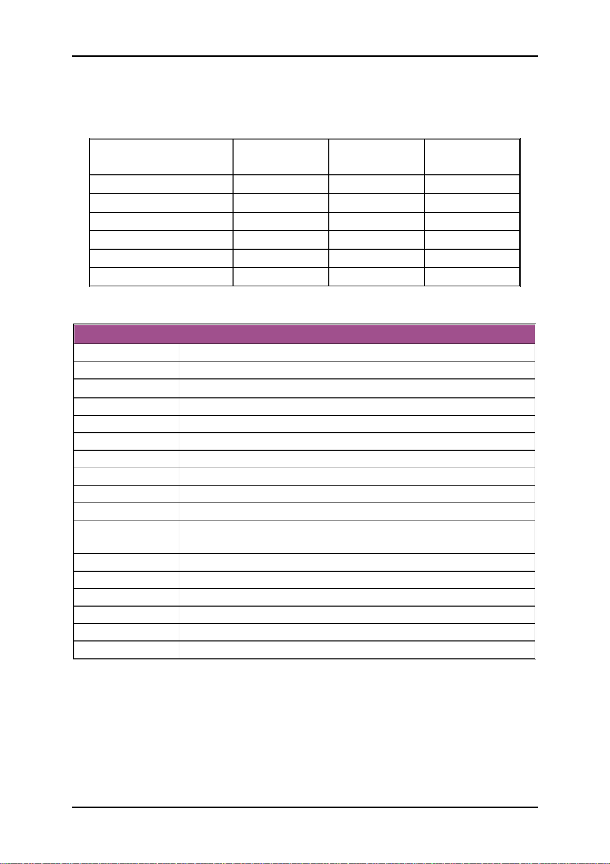
Power Requirements:
Run Burning Test V5.3, RUN time: 10 / 30 Minutes. No Back plane
Item Power ON
CPU +12V
System +12V
System +3.3V
System +5V
System+ Device +12V
System+ Device +5V
Configuration:
CPU Type
SBC BIOS
Memory
VGA Card
VGA Driver
LAN Card
LAN Driver
Audio Card
Audio Driver
Chip Driver
USB 2.0 Driver
Full Loading
10Min
Full Loading
30Min
2.7 3.61 3.57
0.42 0.59 0.63
0.78 1.39 1.47
3.33 5.03 5.25
1.77 0.88 0.87
3.45 5.66 5.85
System Configuration
Intel® Core™ 2 Quad CPU Q9400 @2.66GHz L2:6144K
Portwell, Inc.RUBY-9719 BIOS Rev.:R1.00.E0 (10222009)
Apcer DDR2 800 4GB (ELPIDA E2108ABSE-8G-E)*2
Onboard Intel® G41 Express Chipset
Intel® G41 Express Chipset Version 6.14.10.5068
Onboard Intel® 82583V Gigabit Network Chipset
Intel® 82583V Gigabit Network Connection Version 10.6.15.0
Onboard Realtek ALC662 Audio Chipset
Realtek High Definition Audio Version 5.10.0.5735
Intel® Chipset Device Software Version 9.0.0.1008
Intel® 82801G (ICH7 Family) USB2 Enhanced Host Controller
Version 8.2.0.1008
SCSI Card
SCSI HDD
SATA HDD
Compact Flash
CDROM
Power Supply
Adaptec 29160LP
Seagate ST39173W 8GB
Seagate ST3120813AS 120GB
Apacer 128MB
LITE-ON LH-20A1S DVD-ROM
Portwell.Inc PW-330ATXE-12V
RUBY-9719VG2AR User’s Manual 1-4
Page 8
System Overview
www.ipc2u.ru www.ipc2u.de www.sovio.com Date: 01/07/2016
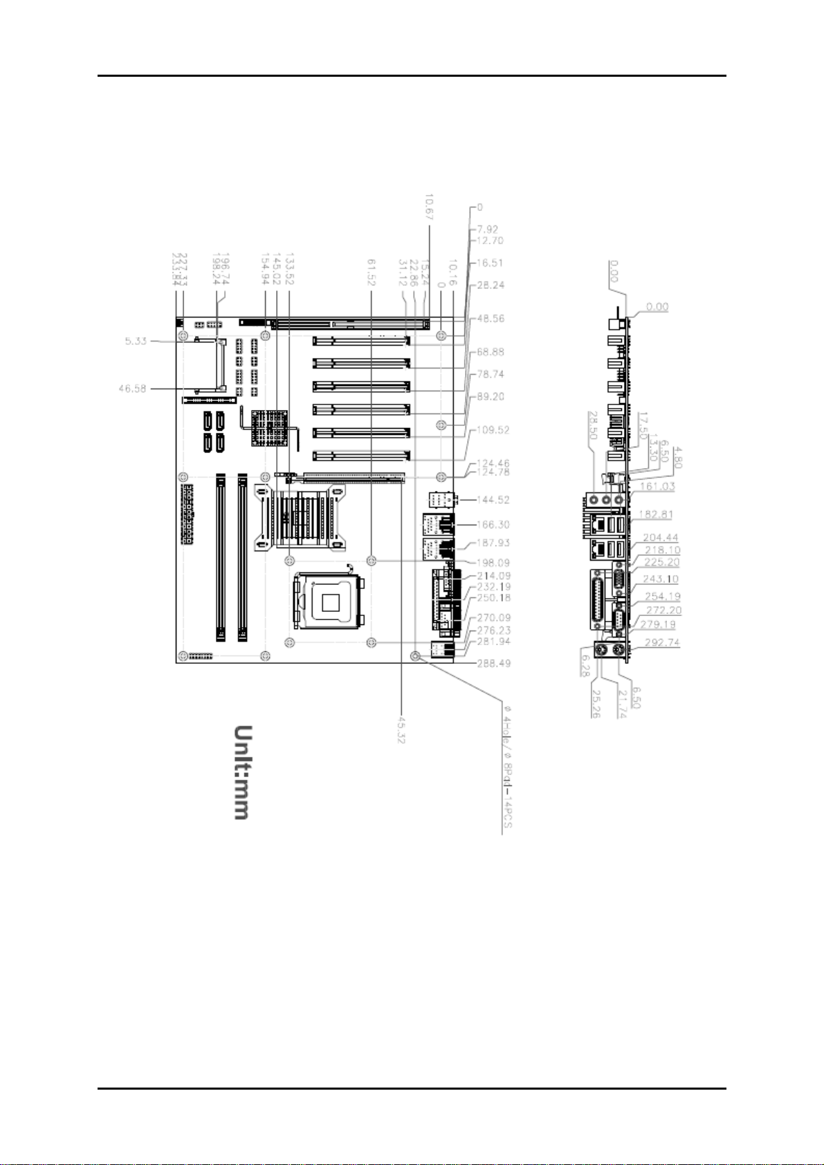
1.3.1 Mechanical Drawing
RUBY-9719VG2AR User’s Manual 1-5
Page 9
System Overview
www.ipc2u.ru www.ipc2u.de www.sovio.com Date: 01/07/2016
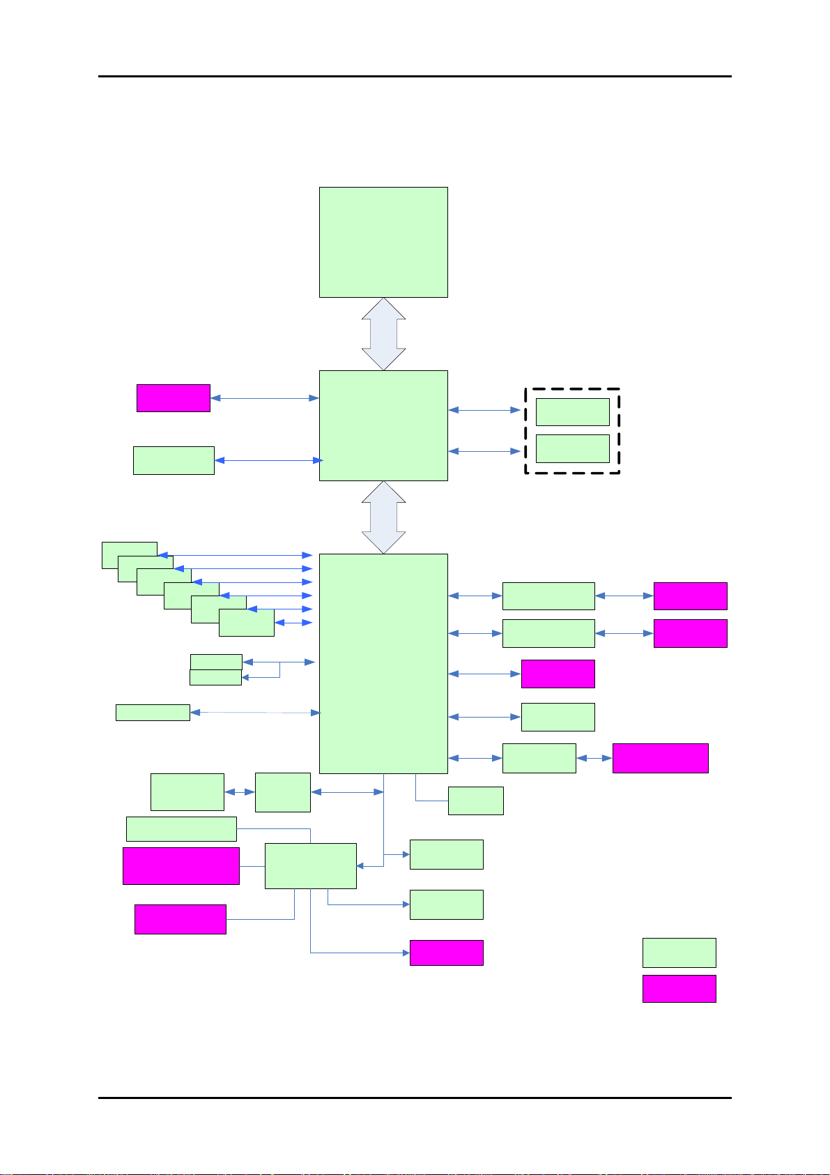
1.4 System Architecture
Processor
VGA
G41
PCIeX16 Slot
FSB 1333MHz / 1066MHz / 800MHz
DDR2
DDR2
PCI
PCI
PCI
4* SATA 2.0
5 * COM RS-232
1 * COM
RS-232/422/485
PCI
PCI
PCI
IDE
CF
PATA
ISA F85226FG
Winbond
83627UHG
®
ICH7R
LPC
PCIex 1
PCIex1
SPI
SPI ROM
TP M pi n heade r
4G DDR2*2 Long DIMMs
Int el 82583V
Int el 82583V
4 * US B 2.0
4 * US B 2.0
ALC662
RJ-45 GbE
RJ-45 GbE
Audi o Jack
8 bit * GPIO
KB/Mouse
Pr int por t
RUBY-9719VG2AR System Block Diagram
RUBY-9719VG2AR User’s Manual 1-6
On board
Rear IO
Page 10
Hardware Configuration
www.ipc2u.ru www.ipc2u.de www.sovio.com Date: 01/07/2016
Chapter 2
Hardware Configuration
This chapter indicates jumpers’, headers’ and connectors’ locations. Users may find
useful information related to hardware settings in this chapter. The default settings
are indicated with a star sign (Ì).
2.1 Jumper Setting
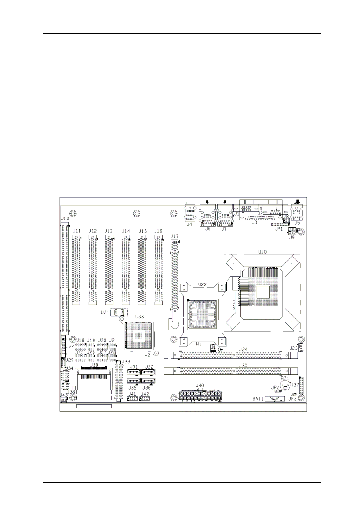
For users to customize RUBY-9719VG2AR’s features. In the following sections, Short
means covering a jumper cap over jumper pins; Open or NC (Not Connected) means
removing a jumper cap from jumper pins. Users can refer to Figure 2-1 for the
Jumper allocations.
Figure 2-1 RUBY-9719VG2AR Jumper & Connector Location
RUBY-9719VG2AR User’s Manual 2-1
Page 11
Hardware Configuration
www.ipc2u.ru www.ipc2u.de www.sovio.com Date: 01/07/2016
The jumper settings are schematically depicted in this manual as follows:
JP1 : RS232, 422, 485 Selection(J2 COM PORT Connector)
JP1 Function
5-6,9-11,10-12,15-17,16-18 Short RS-232 Ì
3-4,7-9,8-10,13-15,14-16,21-22 Short RS-422
1-2,7-9,8-10,19-20 Short RS-485
JP2 : CMOS Clear
JP2 Function
1-2 Short Normal Operation Ì
2-3 Short Clear CMOS Contents
JP3 : Watch Dog Selection
JP3 Function
1-2 Short Enable WDT Ì
1-2 Open Disable WDT
2.2 Connector Allocation
I/O peripheral devices are connected to the interface connectors.
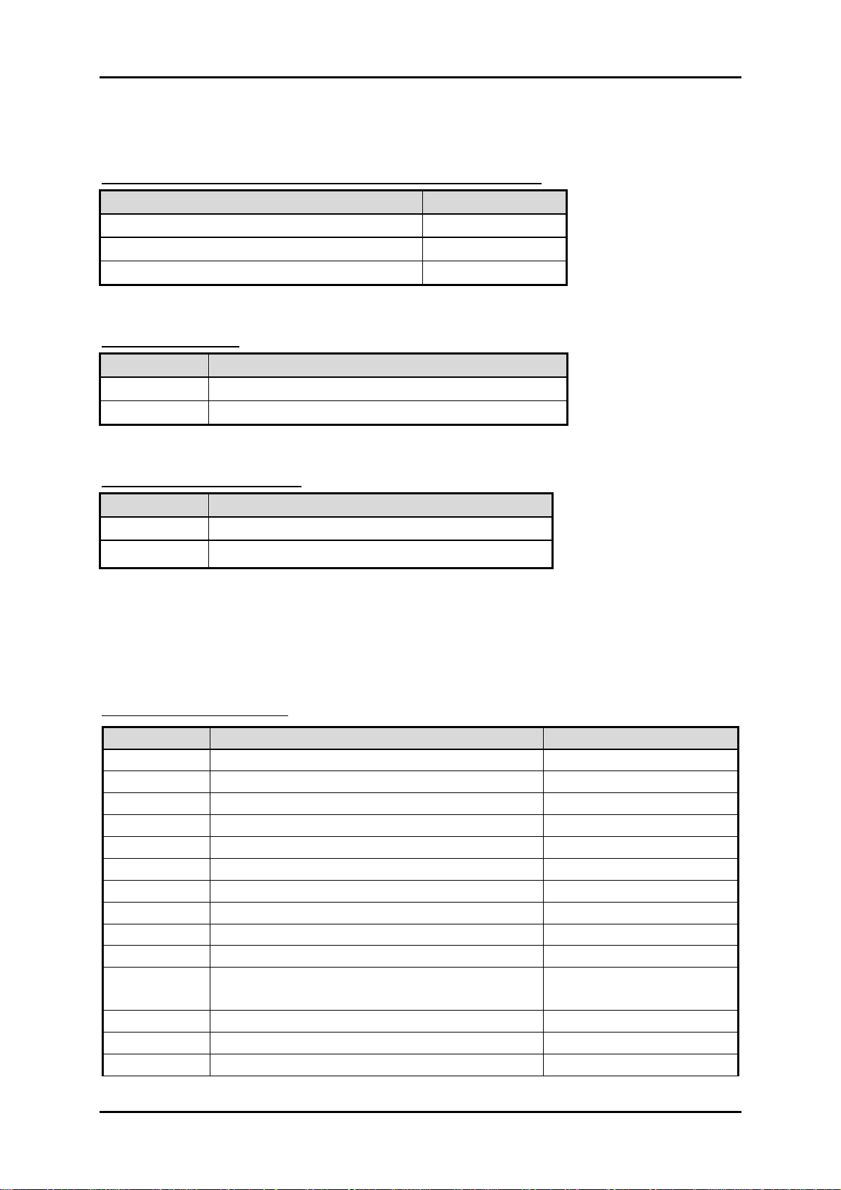
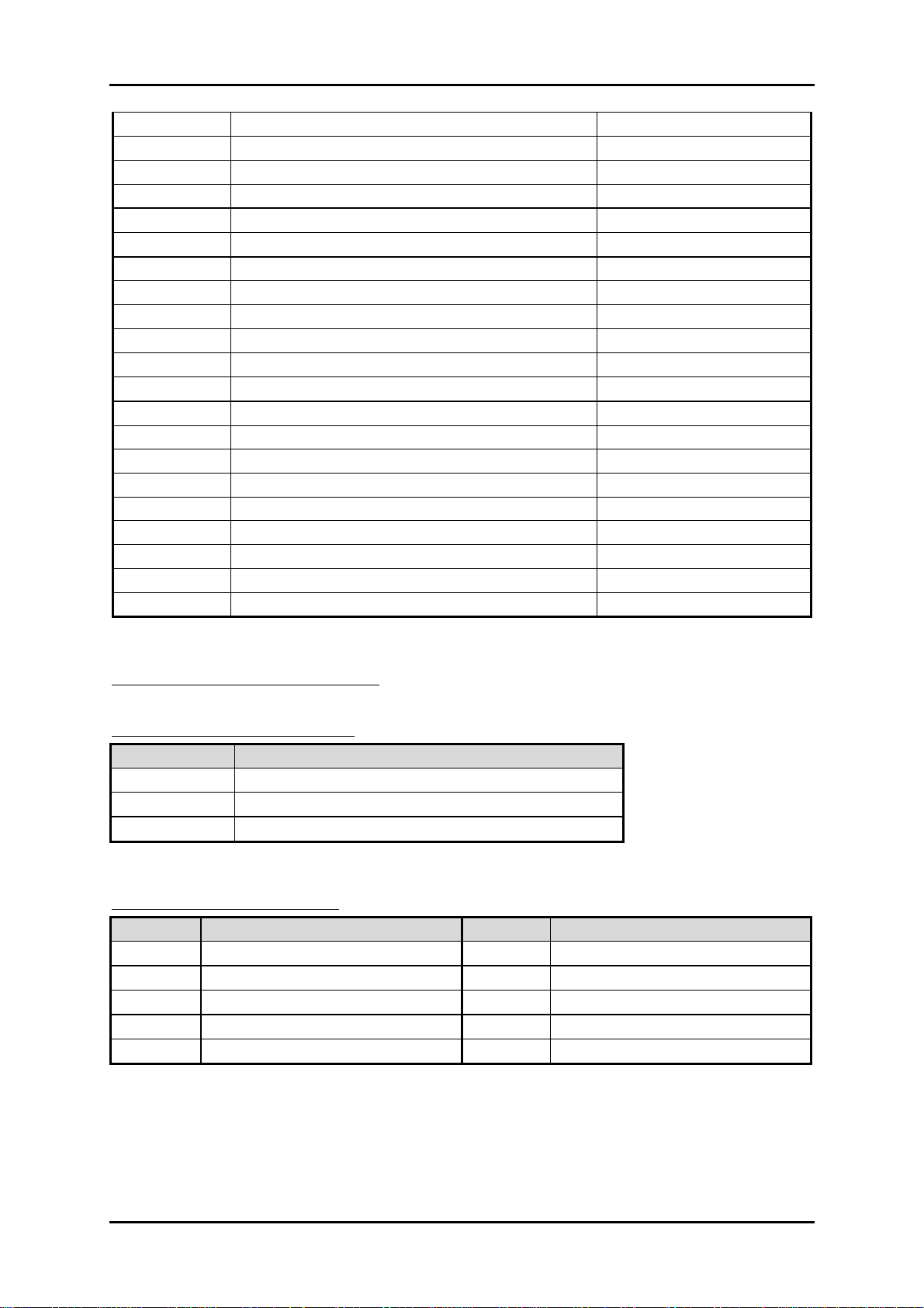
Connector Function List
Connector Function Remark
J1 VGA CONNECTOR
J2 COM2 RS232/422/485 CONNECTOR
J3 Parallel Port CONNECTOR
J4 AUDIO CONNECTOR
J5 KB/MS CONNECTOR
J6 USBX2 + LAN connector
J7 USBX2 + LAN connector
J8 POWER COM2 selection
J9 ATX 4 PIN CONNECTOR
J10 ISA SLOT
J11,J12,J13,
J14,J15,J16
J17 PCI-E X16 CONNECTOR
J18 COM3 CONNECTOR
J19 POWER COM3 selection
PCI SLOT
RUBY-9719VG2AR User’s Manual 2-2
Page 12
Hardware Configuration
www.ipc2u.ru www.ipc2u.de www.sovio.com Date: 01/07/2016
J20 COM5 CONNECTOR
J21 POWER COM5 selection
J22 TPM PIN HEADER
J23 CPU FAN CONNECTOR
J24 DDR2 SLOTA
J25 COM4 CONNECTOR
J26 POWER COM4 selection
J27 COM6 CONNECTOR
J28 POWER COM6 selection
J29 GPIO CONNECTOR
J30 DDR2 SLOTB
J31,J32,J35,J36 SATA CONNECTOR
J33 IDE CONNECTOR
J34 COM1 CONNECTOR
J37 POWER BUTTON
J38 POWER COM1 selection
J39 Compact Flash CONNECTOR
J40 ATX 24P CONNECTOR
J41 USBX2 PIN HEADER
J42 USBX2 PIN HEADER
J43 SYSTEM FAN CONNECTOR
Pin Assignments of Connectors
J8 : POWER COM2 selection
Pin No. Signal Description
1-2 short +5v
3-4 short RI#2
5-6 short +12V
J18 : COM3 CONNECTOR
PIN No. Signal Description PIN No.
1 DCD#3 2 DSR#3
3 RXD#3 4 RTS#3
5 TXD#3 6 CTS#3
7 DTR#3 8 RI#3
9 GND 10 NC
Signal Description
RUBY-9719VG2AR User’s Manual 2-3
Page 13
Hardware Configuration
www.ipc2u.ru www.ipc2u.de www.sovio.com Date: 01/07/2016
J19 : POWER COM3 selection
PIN No. Signal Description
1-2 short +5v
3-4 short RI5-6 short +12V
J20 : COM5 CONNECTOR
PIN No. Signal Description PIN No.
Signal Description
1 DCD#5 2 DSR#5
3 RXD#5 4 RTS#5
5 TXD#5 6 CTS#5
7 DTR#5 8 RI#5
9 GND 10 NC
J21 : POWER COM5 selection
PIN No. Signal Description
1-2 short +5V
3-4 short RI#5
5-6 short +12V
J22 : TPM Pin Header
PIN No. Signal Description PIN No.
Signal Description
1 PCLK_TPM 2 GND
3 LFRAME# 4 NC
5 PLT_RST# 6 VCC
7 LAD3 8 LAD2
9 VCC3 10 LAD1
11 LAD0 12 GND
13 SMB_CLK 14 SMB_DATA
15 3V_DUAL 16 SERIRQ
17 GND 18 NC
19 LPCPD# 20 NC
RUBY-9719VG2AR User’s Manual 2-4
Page 14
Hardware Configuration
www.ipc2u.ru www.ipc2u.de www.sovio.com Date: 01/07/2016
J23 : CPU Fan connector
PIN No. Signal Description
1 GND
2 +12V
3 SENSE
4 PWM
J25 : COM4 CONNECTOR
PIN No. Signal Description PIN No.
1 DCD#4 2 DSR#4
3 RXD#4 4 RTS#4
5 TXD#4 6 CTS#4
7 DTR#4 8 RI#4
9 GND 10 NC
J26 : POWER COM4 selection
PIN No. Signal Description
1-2 short +5V
3-4 short RI#4
5-6 short +12V
J27 : COM6 CONNECTOR
PIN No. Signal Description PIN No.
1 DCD#6 2 DSR#6
3 RXD#6 4 RTS#6
5 TXD#6 6 CTS#6
7 DTR#6 8 RI#6
9 GND 10 NC
J28 : POWER COM6 selection
Signal Description
Signal Description
PIN No. Signal Description
1-2 short +5V
3-4 short RI#6
5-6 short +12V
RUBY-9719VG2AR User’s Manual 2-5
Page 15
Hardware Configuration
www.ipc2u.ru www.ipc2u.de www.sovio.com Date: 01/07/2016
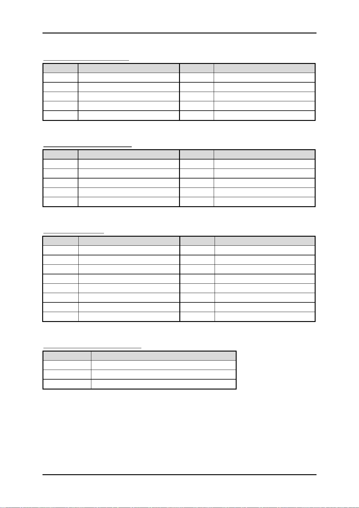
J29 : GPIO CONNECTOR
PIN No. Signal Description PIN No.
Signal Description
1 GPIO20 2 GPIO60
3 GPIO22 4 GPIO61
4 GPIO24 6 GPIO62
5 GPIO27 8 GPIO63
9 GND 10 +5V
J34 : COM1 CONNECTOR
PIN No. Signal Description PIN No.
Signal Description
1 DCD#1 2 DSR#1
3 RXD#1 4 RTS#1
5 TXD#1 6 CTS#1
7 DTR#1 8 RI#1
9 GND 10 NC
J37 : Power Button
PIN No. Signal Description PIN No.
Signal Description
1 POWER LED+ 2 NC
3 NC 4 NC
5 POWER LED- 6 NC
7 NC 8 NC
9 NC 10 POWER BUTTON
11 NC 12 POWER BUTTON
13 HD_LED+ 14 RESET
15 HD_LED- 16 RESET
J38 : POWER COM1 selection
PIN No. Signal Description
1-2 short +5V
3-4 short RI#1
5-6 short +12V
RUBY-9719VG2AR User’s Manual 2-6
Page 16
Hardware Configuration
www.ipc2u.ru www.ipc2u.de www.sovio.com Date: 01/07/2016
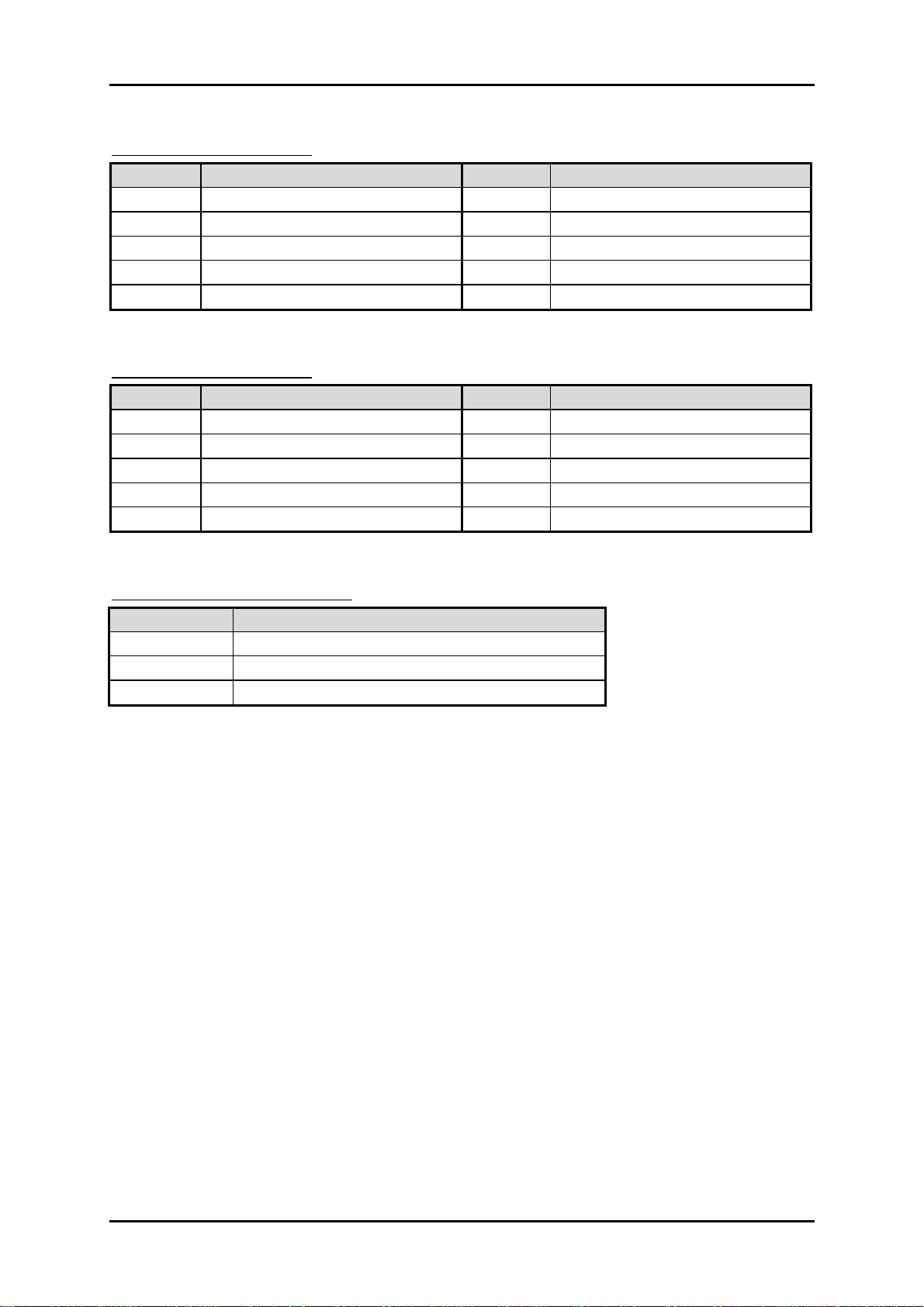
J41 : USBX2 Pin Header
PIN No. Signal Description PIN No.
Signal Description
1 5V_DUAL 2 5V_DUAL
3 D- 4 D-
5 D+ 6 D+
7 GND 8 GND
9 KEY 10 NC
J42 : USBX2 Pin Header
PIN No. Signal Description PIN No.
Signal Description
1 5V_DUAL 2 5V_DUAL
3 D- 4 D-
5 D+ 6 D+
7 GND 8 GND
9 KEY 10 NC
J43 : SYSTEM Fan connector
PIN No. Signal Description
1 GND
2 +12V (PWM)
3 SENSE
RUBY-9719VG2AR User’s Manual 2-7
Page 17
System Installation
www.ipc2u.ru www.ipc2u.de www.sovio.com Date: 01/07/2016
Chapter 3
System Installation
This chapter provides you with instructions to set up your system. The additional
information is enclosed to help you set up onboard PCI device and handle Watch
Dog Timer (WDT) and operation of GPIO in software programming.
3.1 Intel LGA 775 Processor
Installing LGA 775 CPU
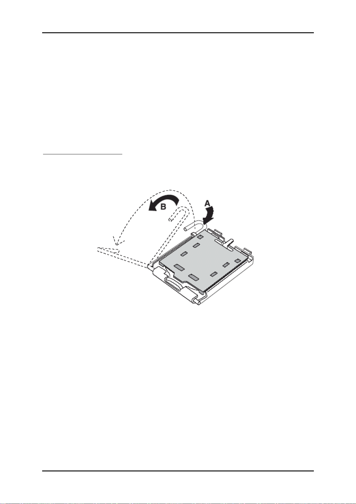
1) Lift the handling lever of CPU socket outwards and upwards to the other end.
Following step A position to step B position (Figure 3-1).
Figure 3-1
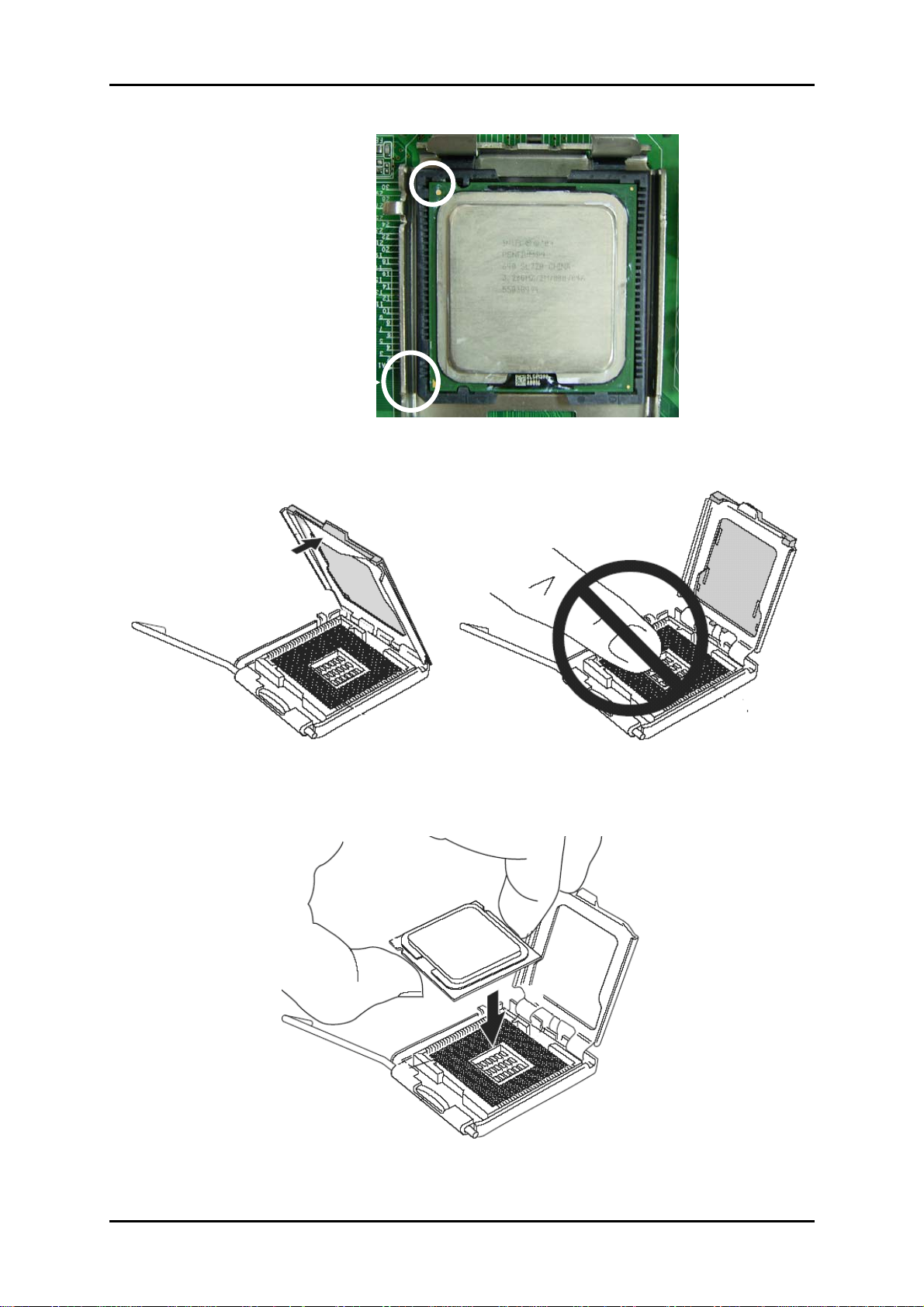
2) Align the processor pins with pinholes on the socket. Make sure that the notched
corner or dot mark (pin 1) of the CPU corresponds to the socket’s bevel end. Then
press the CPU gently until it fits into place (see Fig.3-4). If this operation is not
easy or smooth, don’t do it forcibly. You need to check and rebuild the CPU pin
uniformly.
RUBY-9719VG2AR User’s Manual 3-1
Page 18
System Installation
g
y
www.ipc2u.ru www.ipc2u.de www.sovio.com Date: 01/07/2016
Triangle mark is meanin
first pin position; kindl
assemble and take aim at
notch of top and bottom
between CPU and socket.
Figure 3-2
Figure 3-3
Figure 3-4
RUBY-9719VG2AR User’s Manual 3-2
Page 19
System Installation
www.ipc2u.ru www.ipc2u.de www.sovio.com Date: 01/07/2016
Precaution! (See fig.3-3) Don’t touch directly by your hand or impacts internal align
balls of CPU socket to avoid motherboard destruction, it is a precise actuator.
3) Push down the lever to lock processor chip into the socket once CPU fits.
4) Follow the installation guide of cooling fan or heat sink to mount it on CPU
surface and lock it on the LGA 775 package.
5) You should know LGA 775 processor need extra 12V power source.
Don’t forget to connect 4pin 12V connector to PWR1.
PWR1 : Auxiliary CPU Power Connector
PIN No. Description PIN No.
1
2
GND
GND
3
4
P12V_VRD
P12V_VRD
Description
Removing CPU
1) Unlock the cooling fan first.
2) Lift the lever of CPU socket outwards and upwards to the other end.
3) Carefully lifts up the existing CPU to remove it from the socket.
4) Follow the steps of installing a CPU to change to another one or place handling
bar to close the opened socket.
CPU Application
Supports Intel® Core 2 Quad, Core 2 Duo Desktop processors up to 1333 MHz FSB in
an LGA775 socket.
RUBY-9719VG2AR User’s Manual 3-3
Page 20
System Installation
www.ipc2u.ru www.ipc2u.de www.sovio.com Date: 01/07/2016
3.2 Main Memory
The board also features four DIMM up to 16 GB SDRAM with dual channel DDR2
1066/800.
RUBY-9719VG2AR provide 4 x 240-pin DIMM sockets which supports DDR2
800/1066 MHz as main memory, Non-ECC (Error Checking and Correcting), nonregister functions. The maximum memory size can be up to 16GB capacity.
For system compatibility and stability, do not use memory module without brand.
Memory configuration can be either one double-sided DIMM in either one DIMM
socket or two single-sides DIMM in both sockets.
Watch out the contact and lock integrity of memory module with socket, it will
impact on the system reliability. Follow normal procedures to install memory
module into memory socket. Before locking, make sure that all modules have been
fully inserted into the card slots.
Dual Channel DDR2 DIMM
Dual Channel DDR2 memory technology doubles the bandwidth of memory bus.
Adequate or higher bandwidth of memory than processor would increase system
performance. To enable Dual Channel DDR2 memory technology, you have to
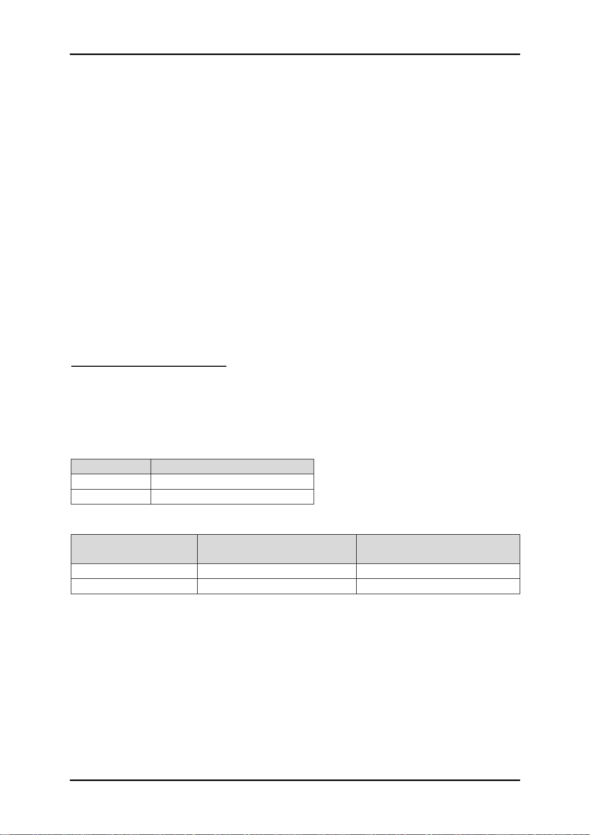
install dual identical memory modules in both memory sockets. Following tables
show bandwidth information of different processor and memory configurations.
CPU FSB Bandwidth
1066MHz 8.5GB/s
800MHz 6.4GB/s
Memory Frequency
Dual Channel DDR2
Bandwidth
Single Channel DDR2
Bandwidth
1066MHz 17GB/s 8.5GB/s
800MHz 12.8GB/s 6.4GB/s
Note:
To maintain system stability, don’t change any of DRAM parameters in BIOS setup
to upgrade system performance without acquiring technical information.
RUBY-9719VG2AR User’s Manual 3-4
Page 21

System Installation
www.ipc2u.ru www.ipc2u.de www.sovio.com Date: 01/07/2016
3.3 Installing the Single Board Computer
To install your RUBY-9719VG2AR into standard chassis or proprietary environment,
please perform the following:
Step 1 : Check all jumpers setting on proper position
Step 2 : Install and configure CPU and memory module on right position
Step 3 : Place RUBY-9719VG2AR into the dedicated position in the system
Step 4 : Attach cables to existing peripheral devices and secure it
WARNING
Please ensure that SBC is properly inserted and fixed by mechanism.
Note:
Please refer to section 3.3.1 to 3.3.5 to install INF/VGA/Ethernet/Audio drivers.
3.3.1 Chipset Component Driver
The chipset on RUBY-9719VG2AR is a new chipset that a few old operating systems
might not be able to recognize. To overcome this compatibility issue, for Windows
Operating Systems such as Windows XP, please install its INF before any of other
Drivers are installed. You can select the Intel Chipset driver from the RUBY9719VG2AR CD-title.
3.3.2 Intel Integrated Graphics GMCH Chip
RUBY-9719VG2AR comes with the Intel
5.0 display memory up to 287 MB. Shared 32 accompany it to 128MB system
Memory with Total Graphics Memory. This combination makes RUBY-9719VG2AR
an excellent piece of multimedia hardware.
With no additional video adaptor, this onboard video will usually be the system
display output. By adjusting the BIOS setting to disable on-board VGA, an add-on
PCI-Express by 16 VGA card can take over the system display.
Drivers Support
®
GMA X4500 graphics supporting DVMT
Please select Intel Graphic driver from the RUBY-9719VG2AR Driver CD-title.
Driver supports Windows XP.
RUBY-9719VG2AR User’s Manual 3-5
Page 22
System Installation
www.ipc2u.ru www.ipc2u.de www.sovio.com Date: 01/07/2016
3.3.3 On-board Fast Ethernet Controllers
Drivers Support
Please select Intel Ethernet driver from the RUBY-9719VG2AR Driver CD-title to
install those two integrated Intel® 82574L Gigabit Ethernet controller drivers. Those
two drivers support Windows XP.
LED Indicator (for LAN status)
ROBO-8779VG2AR provides two LED indicators to report Intel 82574L & 82574L
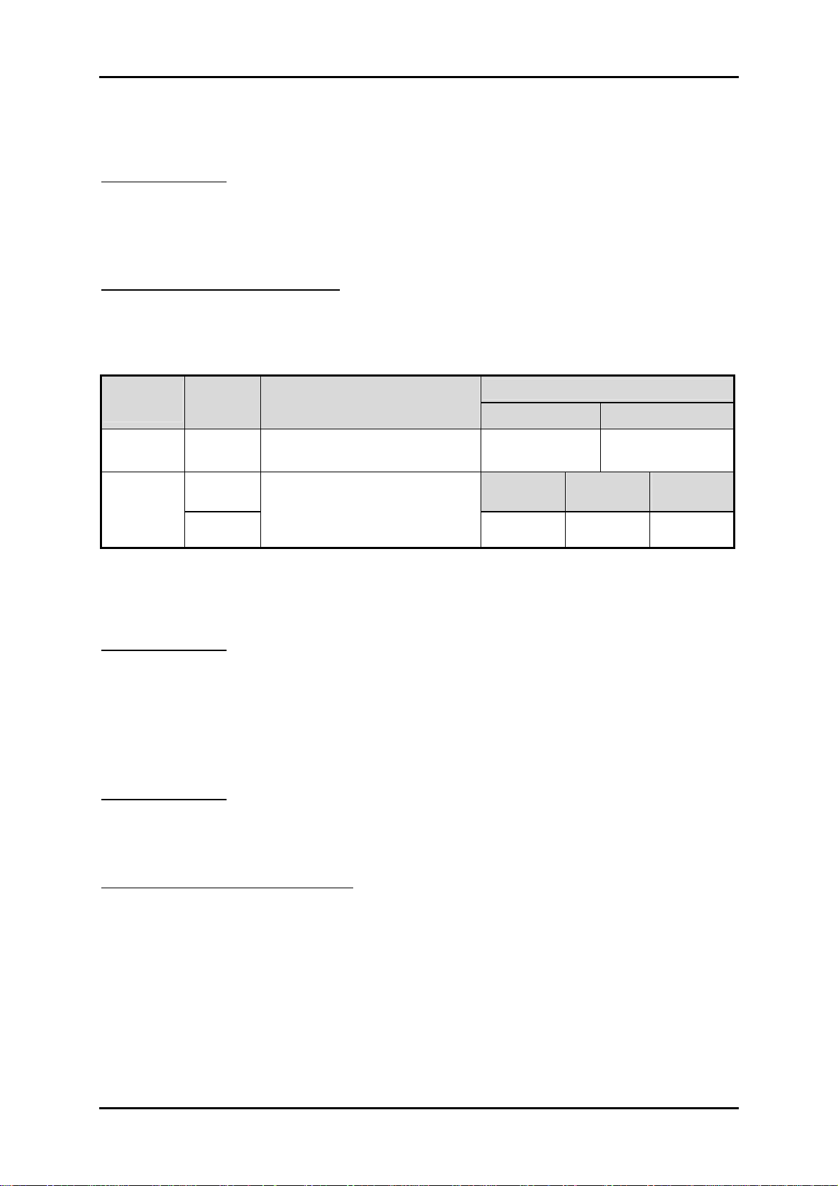
Gigabit Ethernet interface status. Please refer to the table below as a quick reference
guide.
82574L
&82574L
Status
LED
Speed
LED
Color Name of LED
Orange LAN Linked & Active LED
Orange
LAN speed LED
Green
Operation of Ethernet Port
Linked Active
On Blinking
Giga
Mbps
Orange
100
Mbps
10
1Mbps
Green Off
3.3.4 On-board High Definition Audio Controller
Drivers Support
Please select the Realtek High Definition Codec Audio driver from RUBY9719VG2AR Driver CD-title. The driver supports Windows XP.
3.3.5 Intel Matrix Storage Manager Device
Drivers Support
Please find utility tool for Intel ICH7R of RUBY-9719VG2AR CD-title. The drivers
support Windows XP.
Installing Serial ATA hard disks
The RUBY-9719VG2AR supports Four Serial ATA hard disk drives. For optimal
performance, install identical drives of the same model and capacity when creating a
disk array.
To install the SATA hard disks for a RAID configuration:
1. Install the SATA hard disks into the drive bays.
2. Connect the SATA signal cables.
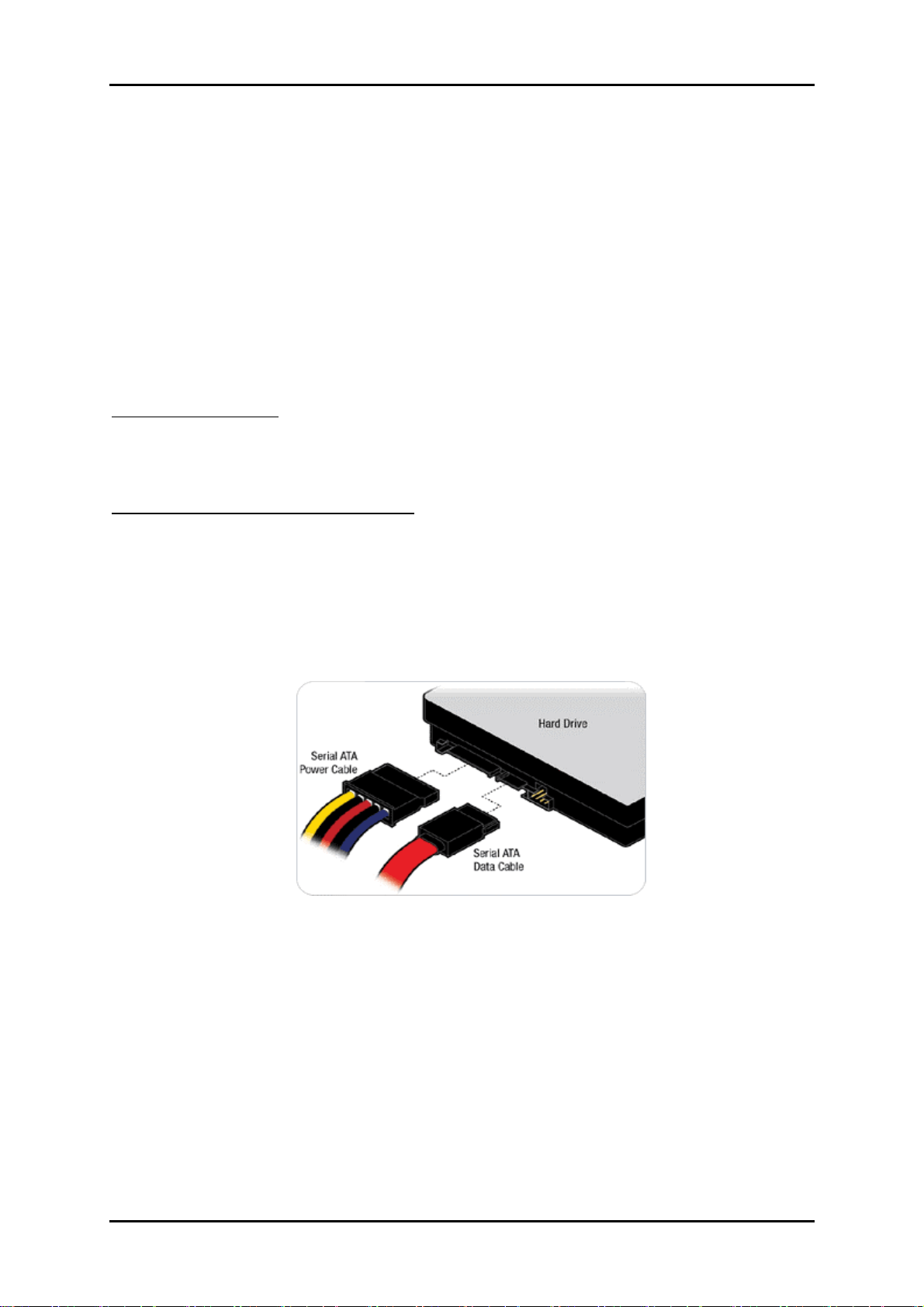
3. Connect a SATA power cable to the power connector on each drive.
RUBY-9719VG2AR User’s Manual 3-6
Page 23

System Installation
www.ipc2u.ru www.ipc2u.de www.sovio.com Date: 01/07/2016
Intel RAID configurations
This RUBY-9719VG2AR supports RAID 0, RAID 1, RAID 5, RAID (1+0) and Intel®
Matrix Storage configurations for Serial ATA hard disks drives through the Intel
ICH7R Southbridge chip.
RAID configurations
RAID 0 (Data striping) optimizes two identical hard disk drives to read and write
data in parallel, interleaved stacks. Two hard disks perform the same work as a
single drive but at a sustained data transfer rate, double that of a single disk alone,
thus improving data access and storage. Use of two new identical hard disk drives is
required for this setup.
RAID 1 (Data mirroring) copies and maintains an identical image of data from one
drive to a second drive. If one drive fails, the disk array management software
directs all applications to the surviving drive as it contains a complete copy of the
data in the other drive. This RAID configuration provides data protection and
increases fault tolerance to the entire system. Use two new drives or use an existing
drive and a new drive for this setup. The new drive must be of the same size or
larger than the existing drive.
RAID 5 stripes both data and parity information across three or more hard disk
drives. Among the advantages of RAID 5 configuration include better HDD
performance, fault tolerance, and higher storage capacity. The RAID 5 configuration
is best suited for transaction processing, relational database applications, enterprise
resource planning, and other business systems. Use a minimum of three identical
hard disk drives for this setup.
RAID 10 is data striping and data mirroring combined without parity (redundancy
data) having to be calculated and written. With the RAID 10 configuration you get
all the benefits of both RAID 0 and RAID 1 configurations. Use four new hard disk
drives or use an existing drive and three new drives for this setup.
Intel Matrix Storage Manager. The Intel® Matrix Storage technology supported by
the ICH7R chip allows you to create a RAID 0 and a RAID 1 set using only two
identical hard disk drives. The Intel® Matrix Storage technology creates two
partitions on each hard disk drive to create a virtual RAID 0 and RAID 1 sets. This
technology also allows you to change the hard disk drive partition size without
losing any data.
RUBY-9719VG2AR User’s Manual 3-7
Page 24

System Installation
www.ipc2u.ru www.ipc2u.de www.sovio.com Date: 01/07/2016
3.4 Clear CMOS Operation
The following table indicates how to enable/disable Clear CMOS Function hardware
circuit by putting jumpers at proper position.
JP2 : CMOS Clear
JP2 Function
1-2 Short Normal Operation Ì
2-3 Short Clear CMOS Contents
3.5 WDT Programming Guide
The working algorithm of the WDT function can be simply described as a counting
process. The Time-Out Interval can be set through software programming. The
availability of the time-out interval settings by software or hardware varies from
boards to boards.
RUBY-9719VG2AR allows users to control WDT through dynamic software
programming. The WDT starts counting when it is activated. It sends out a signal to
system reset or to non-maskable interrupt (NMI), when time-out interval ends. To
prevent the time-out interval from running out, a re-trigger signal will need to be
sent before the counting reaches its end. This action will restart the counting process.
A well-written WDT program should keep the counting process running under
normal condition. WDT should never generate a system reset or NMI signal unless
the system runs into troubles.
The related Control Registers of WDT are all included in the following sample
program that is written in C language. User can fill a non-zero value into the Timeout Value Register to enable/refresh WDT. System will be reset after the Time-out
Value to be counted down to zero. Or user can directly fill a zero value into Time-out
Value Register to disable WDT immediately. To ensure a successful accessing to the
content of desired Control Register, the sequence of following program codes should
be step-by-step run again when each register is accessed.
Additionally, there are maximum 2 seconds of counting tolerance that should be
considered into user’ application program. For more information about WDT, please
refer to Winbond W83627UHG data sheet.
There are two PNP I/O port addresses that can be used to configure WDT,
1) 0x2E:EFIR (Extended Function Index Register, for identifying CR index number)
2) 0x2F:EFDR (Extended Function Data Register, for accessing desired CR)
RUBY-9719VG2AR User’s Manual 3-8
Page 25

System Installation
www.ipc2u.ru www.ipc2u.de www.sovio.com Date: 01/07/2016
Below are some example codes, which demonstrate the use of WDT.
// Enter Extended Function Mode
outp(0x002E, 0x87);
outp(0x002E, 0x87);
// Enable Pin 77 as WDTO#
// Select Logic Device 8
outp(0x002E, 0x07);
outp(0x002F, 0x08);
// Active Logic Device 8
outp(0x002E, 0x30);
outp(0x002F, 0x01);
// Select Count Mode
outp(0x002E, 0xF5);
outp(0x002F, (inp(0x002F) & 0xF7) | ( Count-mode Register & 0x08));
// Specify Time-out Value
outp(0x002E, 0xF6);
outp(0x002F, Time-out Value Register );
// Disable WDT reset by keyboard/mouse interrupts
outp(0x002E, 0xF7);
outp(0x002F, 0x00);
// Exit Extended Function Mode
outp(0x002E, 0xAA);
Definitions of Variables:
Value of Count-mode Register :
1) 0x00 -- Count down in seconds (Bit3=0)
2) 0x08 -- Count down in minutes (Bit3=1)
Value of Time-out Value Register :
1) 0x00 -- Time-out Disable
2) 0x01~0xFF -- Value for counting down
RUBY-9719VG2AR User’s Manual 3-9
Page 26
System Installation
www.ipc2u.ru www.ipc2u.de www.sovio.com Date: 01/07/2016
3.6 GPIO Programming Guide
The RUBY-9719VG2AR provides 8 input/output ports that can be individually
configured to perform a simple basic I/O function. Users can configure each
individual port to become an input or output port by programming register bit of
I/O Selection. To invert port value, the setting of Inversion Register has to be made.
Port values can be set to read or write through Data Register.
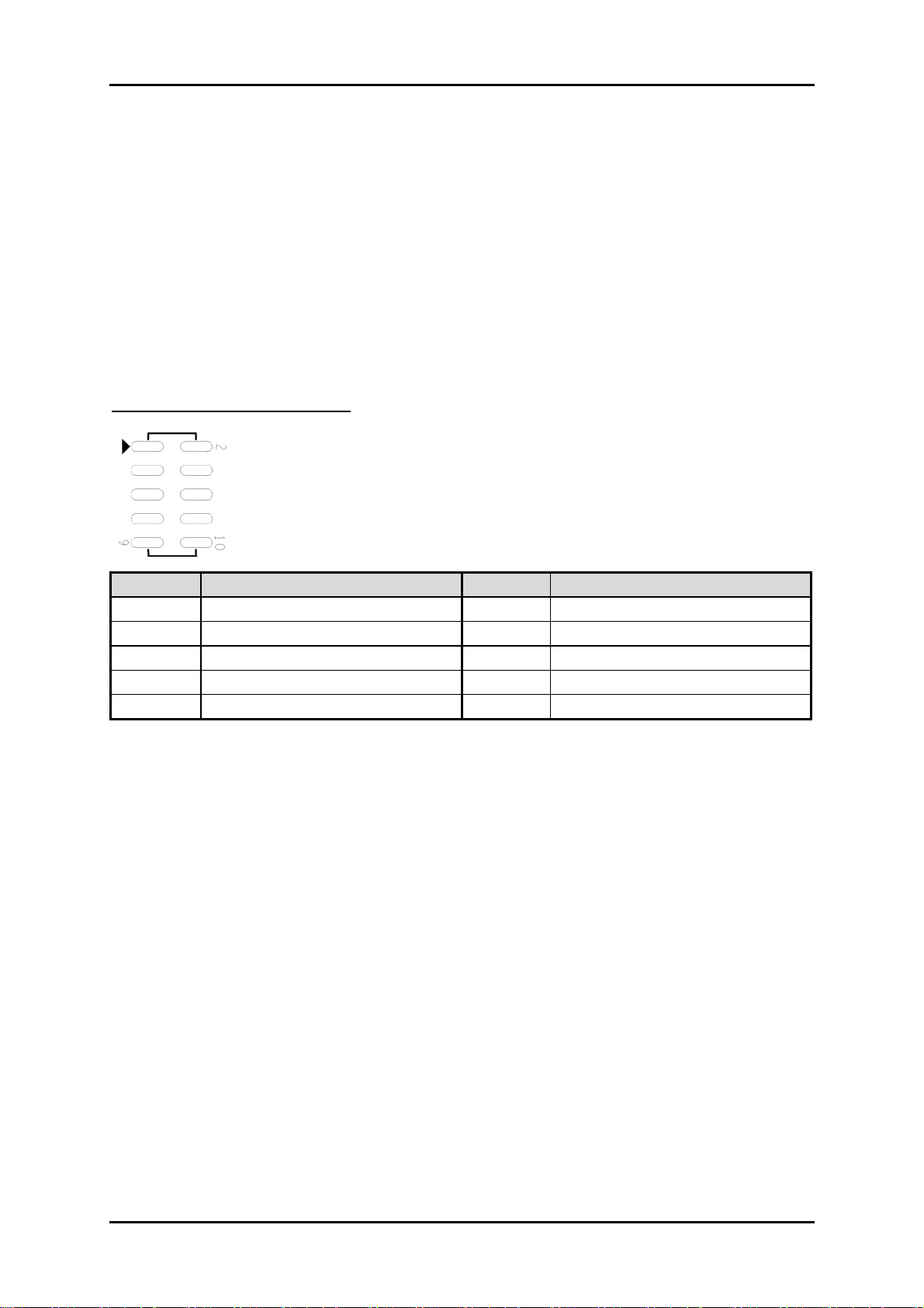
The GPIO port is located on J31 shown as follows. Please note: DO NOT SHORT-
CIRCUIT PIN 9 AND 10 OF J31!
J29 : 8-bit GPIO pin header
PIN No. Signal Description PIN No.
Signal Description
1 GPIO23 2 GPIO60
3 GPIO22 4 GPIO61
5 GPIO24 6 GPIO62
7 GPIO27 8 GPIO63
9 Ground 10 +5V
All 8 GPIO pins come from W83627UHG, Winbond. All of them are TTL-level, bidirectional pins and open-drain outputs with 12mA sink capability.
Users can refer to W83627UHG, Winbond datasheet to configure each individual
port to become an input or output port by programming register bit of I/O Selection.
To invert port value, the setting of Inversion Register has to be made. Port values can
be set to read or write through Data Register.
RUBY-9719VG2AR User’s Manual 3-10
Page 27
BIOS Setup Information
www.ipc2u.ru www.ipc2u.de www.sovio.com Date: 01/07/2016
Chapter 4
BIOS Setup Information
RUBY-9719VG2AR is equipped with the AMI BIOS stored in Flash ROM. These
BIOS has a built-in Setup program that allows users to modify the basic system
configuration easily. This type of information is stored in CMOS RAM so that it
is retained during power-off periods. When system is turned on, RUBY-9719VG2AR
communicates with peripheral devices and checks its hardware resources against the
configuration information stored in the CMOS memory. If any error is detected, or
the CMOS parameters need to be initially defined, the diagnostic program will
prompt the user to enter the SETUP program. Some errors are significant enough
to abort the start up.
4.1 Entering Setup -- Launch System Setup
Power on the computer and the system will start POST (Power On Self Test)
process. When the message below appears on the screen, press <Del> key to enter
Setup.
Press <Del> to enter SETUP
If the message disappears before you respond and you still wish to enter Setup,
restart the system by turning it OFF and On or pressing the RESET button. You
may also restart the system by simultaneously pressing <Ctrl>, <Alt>, and <Delete>
keys.
Press <F1> to Run SETUP or Resume
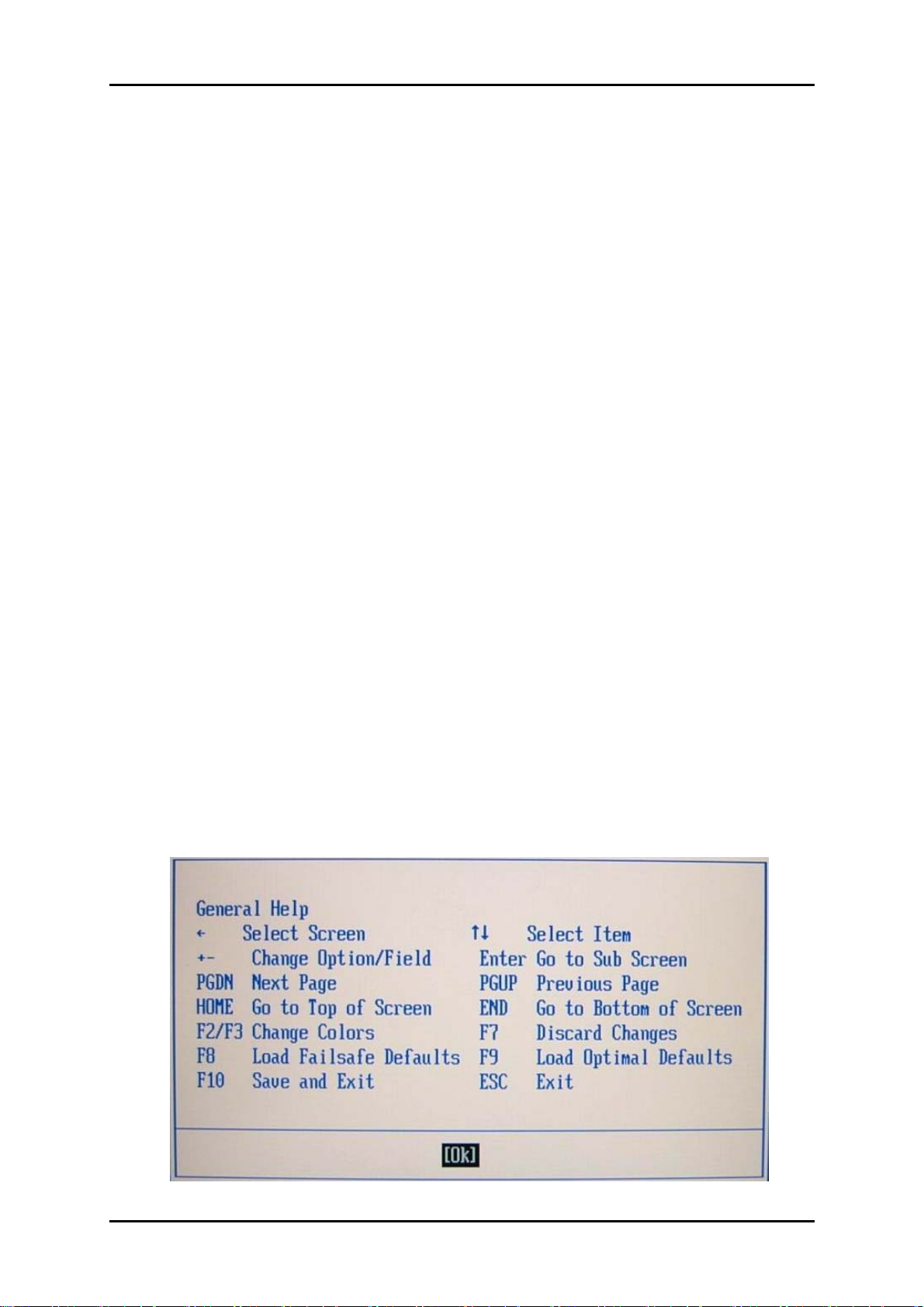
The BIOS setup program provides a General Help screen. You can call up this screen
from any menu by simply pressing <F1>. The Help screen lists the appropriate keys
to use and the possible selections for the highlighted item. Press <Esc> to exit the
Help screen.
RUBY-9719VG2AR User’s Manual 4-1
Page 28
BIOS Setup Information
www.ipc2u.ru www.ipc2u.de www.sovio.com Date: 01/07/2016
4.2 Main
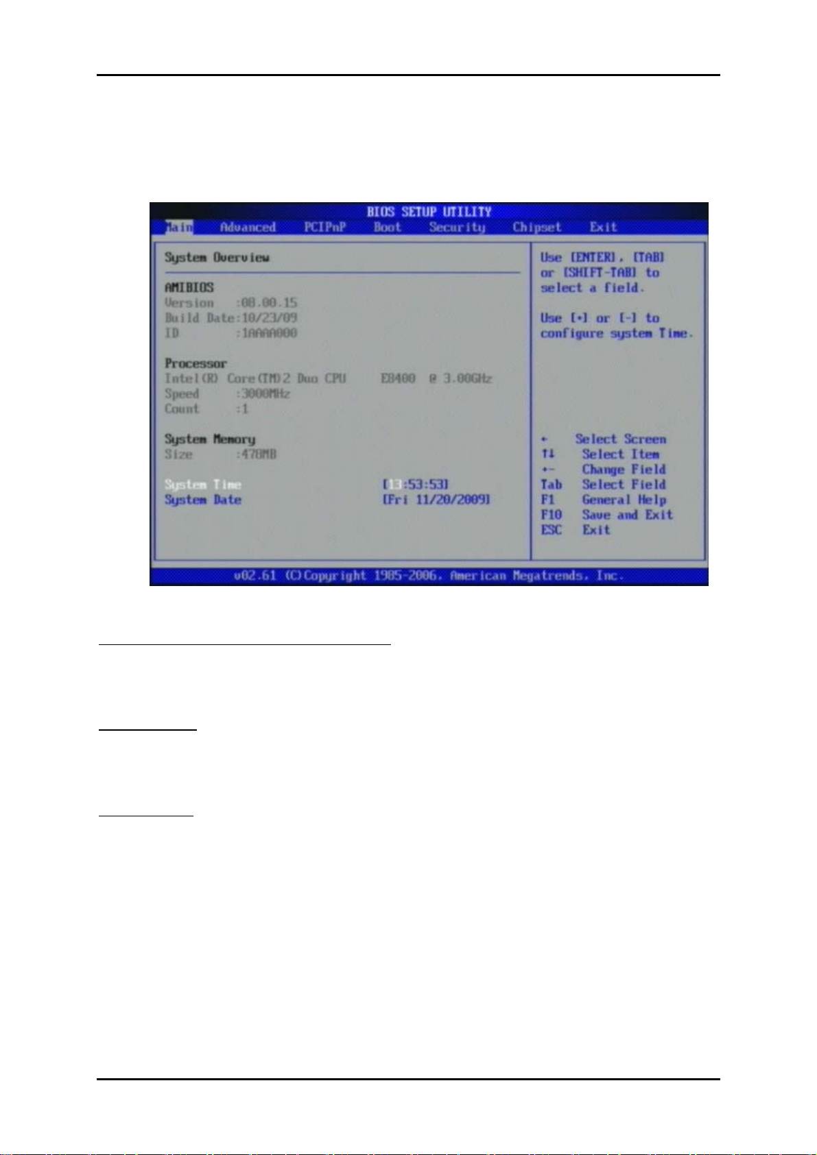
Use this menu for basic system configurations, such as time, date etc.
AMI BIOS, Processor, System Memory
These items show the firmware and hardware specifications of your system. Read
only.
System Time
The time format is <Hour> <Minute> <Second>. Use [+] or [-] to configure
system Time.
System Date
The date format is <Day>, <Month>, <Date>, <Year>. Use [+] or [-] to configure
system Date.
RUBY-9719VG2AR User’s Manual 4-2
Page 29
BIOS Setup Information
www.ipc2u.ru www.ipc2u.de www.sovio.com Date: 01/07/2016
4.3 Advanced
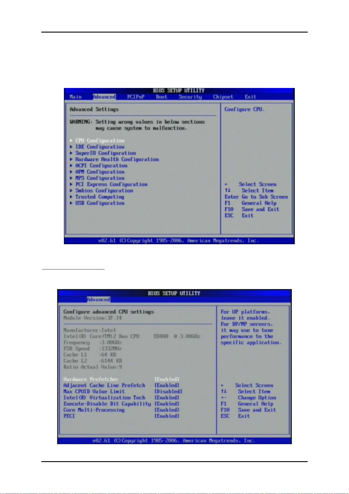
Use this menu to set up the items of special enhanced features.
CPU Configuration
These items show the advanced specifications of your CPU. Read only.
RUBY-9719VG2AR User’s Manual 4-3
Page 30
BIOS Setup Information
www.ipc2u.ru www.ipc2u.de www.sovio.com Date: 01/07/2016
Execute-Disable Bit Capability
Disabled force the XD feature flag to always return 0.
The choice: Disabled, Enabled.
PECI
When enabled, enables PECI interface.
The choice: Disabled, Enabled.
Core Multi-Processing
Disabled disable one execution core of each CPU die.
The choice: Disabled, Enabled.
Intel (R) SpeedStep (tm) tech
Disabled / Enabled GV3 tech function.
The choice: Disabled, Enabled.
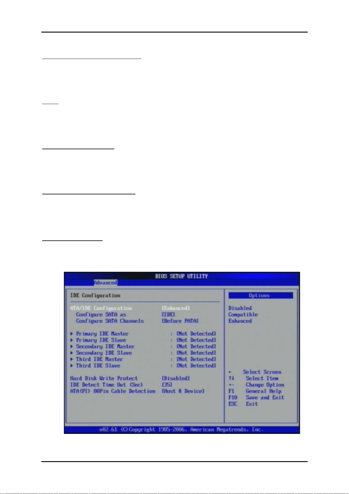
IDE Configuration
The IDE Configuration the IDE devices, such as hard disk drive or CD-ROM drive. It
uses a separate sub menu to configure each hard disk drive (Master and Slave).
RUBY-9719VG2AR User’s Manual 4-4
Page 31
BIOS Setup Information
www.ipc2u.ru www.ipc2u.de www.sovio.com Date: 01/07/2016
SATA#1 Configuration
The choice: Disabled, Compatible, Enabled.
Configure SATA#1 as
This setting specifies the function of the on-chip SATA#1 controller.
The choice: IDE, RAID, AHCI.
SATA#2 Configuration
The choice: Disabled, Enabled.
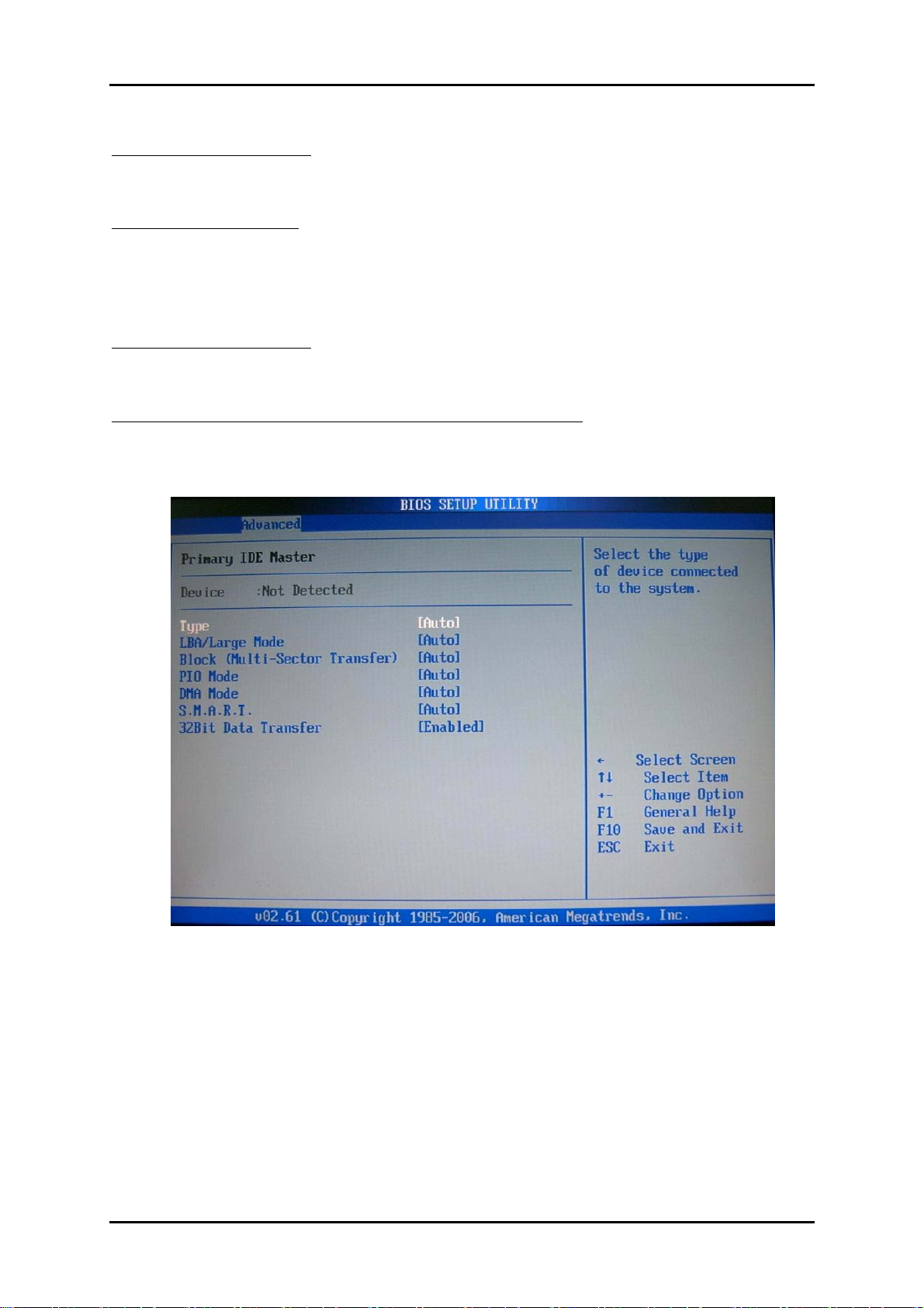
Primary / Secondary / Third / Fourth IDE Master / Slave
While entering setup, BIOS auto detects the presence of IDE devices. This displays
the status of auto detection of IDE devices.
[Type] Press PgUp/<+> or PgDn/<-> to select [Manual], [None] or [Auto] type.
you can use [Manual] to define your own drive type manually.
[LBA/Large Mode] Enabling LBA causes Logical Block Addressing to be used in
place of Cylinders, Heads and Sectors.
[Block (Multi-Sector Transfer)] Any selection except Disabled determines the number
of sectors transferred per block.
RUBY-9719VG2AR User’s Manual 4-5
Page 32

BIOS Setup Information
www.ipc2u.ru www.ipc2u.de www.sovio.com Date: 01/07/2016
[PIO Mode] Indicates the type of PIO (Programmed Input/Output)
[DMA Mode] Indicates the type of Ultra DMA
[S.M.A.R.T.] This allows you to activate the S.M.A.R.T. (Self-Monitoring Analysis &
Reporting Technology) capability for the hard disks. S.M.A.R.T is a utility that
monitors your disk status to predict hard disk failure. This gives you an opportunity
to move data from a hard disk that is going to fail to a safe place before the hard disk
becomes offline.
[32 Bit Data Transfer] Enable/Disable 32-bit Data Transfer.
Hard Disk Write Protect
Disabled/Enabled device write protection, this will be effective only if device is
accessed through BIOS.
The choice: Disabled, Enabled.
IDE Detect Time Out (Sec)
Select the time out value for detecting ATA/ATAPI device (s).
The choice: 0, 5, 10, 15, 20, 25, 30, 35.
ATA (PI) 80Pin Cable Detection
Select the mechanism for detecting 80Pin ATA (PI) cable.
The choice: Host & Device, Host, Device.
RUBY-9719VG2AR User’s Manual 4-6
Page 33
BIOS Setup Information
www.ipc2u.ru www.ipc2u.de www.sovio.com Date: 01/07/2016
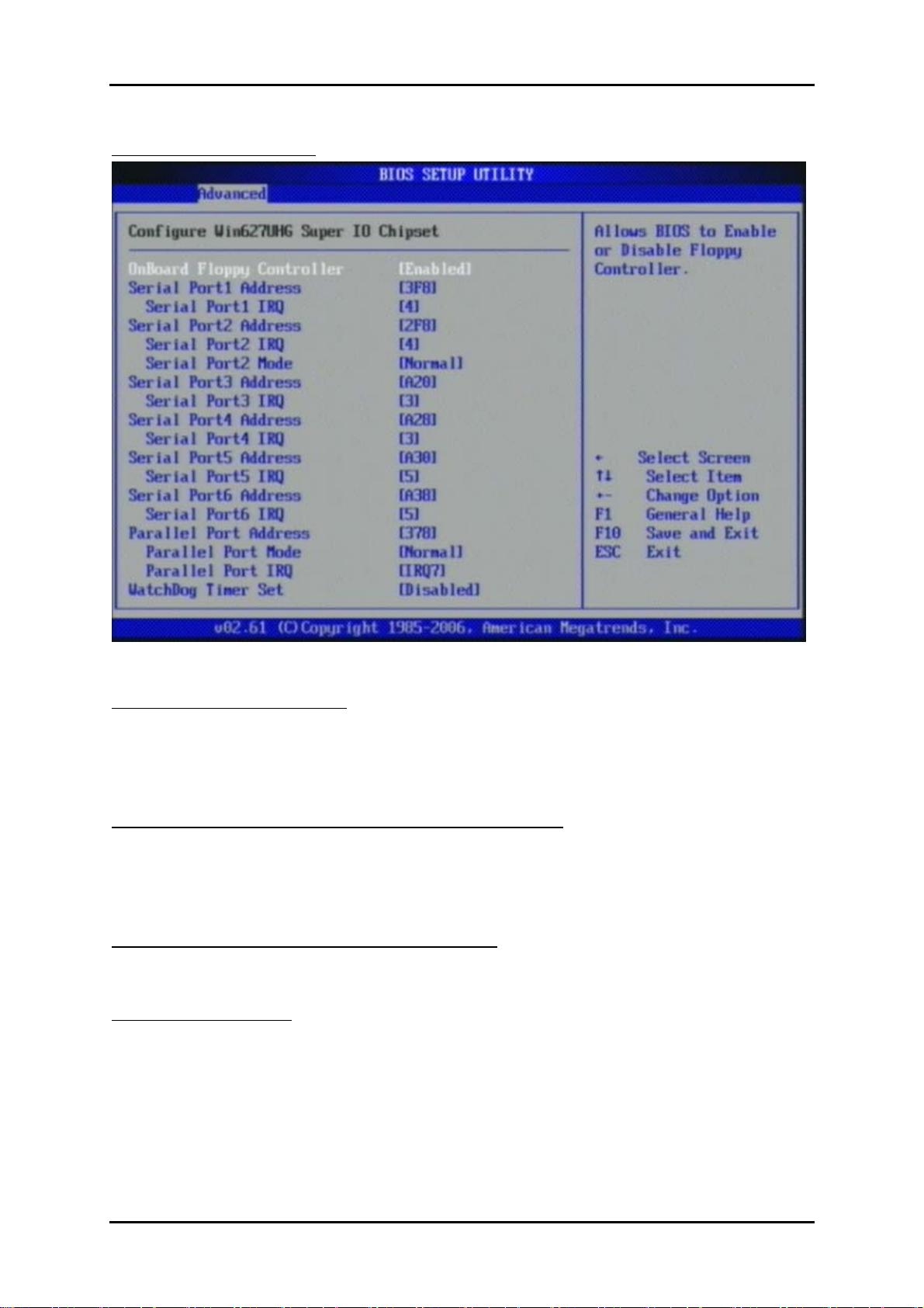
Super IO Configuration
OnBoard Floppy Controller
This item allows enable/disable onboard Floppy disk controller.
The choice: Disabled, Enabled.
Serial Port 1/Port 2/Port 3/Port 4/Port 5/Port 6 Address
Allows BIOS Select Serial Port1 or Port2 Base Addresses.
The choice: Disabled, 3F8/IRQ4, 3E8/IRQ4, 2E8/IRQ3/IRQ5 A3B
Serial Port 2 /Port 3/Port 4/Port 5 /Port 6 Mode
This item allows users to select Infrared transmission mode.
Parallel Port Address
This item allows you to configuring I/O of the onboard parallel port.
The choice: Disabled, 378, 278, 3BC.
RUBY-9719VG2AR User’s Manual 4-7
Page 34
BIOS Setup Information
www.ipc2u.ru www.ipc2u.de www.sovio.com Date: 01/07/2016
Parallel Port Mode
There are five different modes for the onboard parallel port:
Normal
Bi-Directional
ECP
EPP
ECP & EPP
Switch to Normal mode
Switch to Bi-Directional mode
Switch to ECP mode
Switch to EPP mode
Switch to ECP & EPP mode
Parallel Port IRQ
Allows BIOS Select Parallel Port IRQ.
The choice: IRQ5, IRQ7.
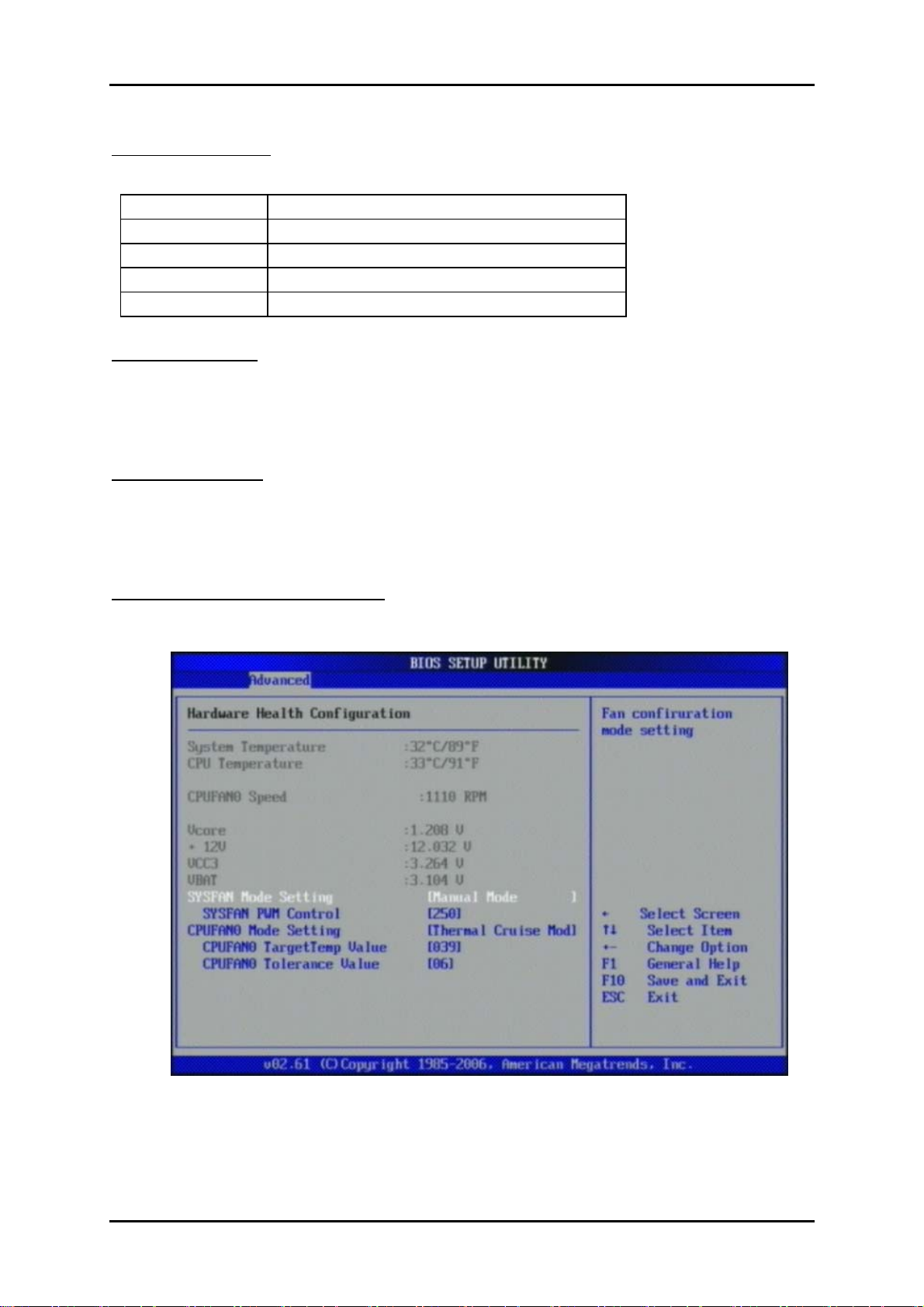
Watch Dog Timer
This BIOS testing option is able to reset the system according to the selected table.
The choice: Disabled, 30, 60, 90, 120, 150, 180, 210 sec.
Hardware Health Configuration
Configuration / monitor the Hardware Health.
RUBY-9719VG2AR User’s Manual 4-8
Page 35
BIOS Setup Information
www.ipc2u.ru www.ipc2u.de www.sovio.com Date: 01/07/2016
H/W Health Function
Enable or Disable Hardware Health Monitoring Device.
The choice: Disabled, Enabled.
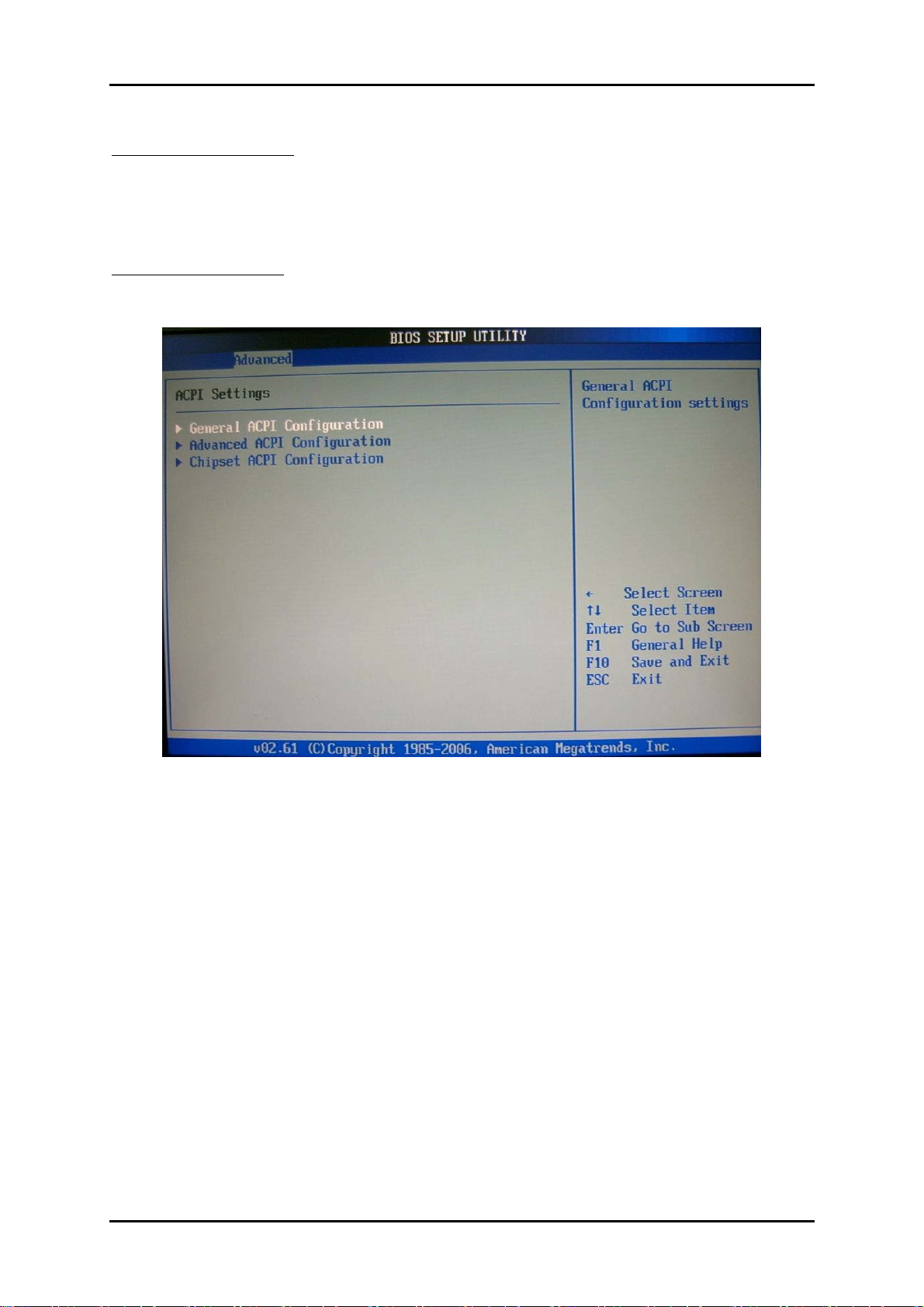
ACPI Configuration
Select for Advanced ACPI Configuration.
RUBY-9719VG2AR User’s Manual 4-9
Page 36
BIOS Setup Information
www.ipc2u.ru www.ipc2u.de www.sovio.com Date: 01/07/2016
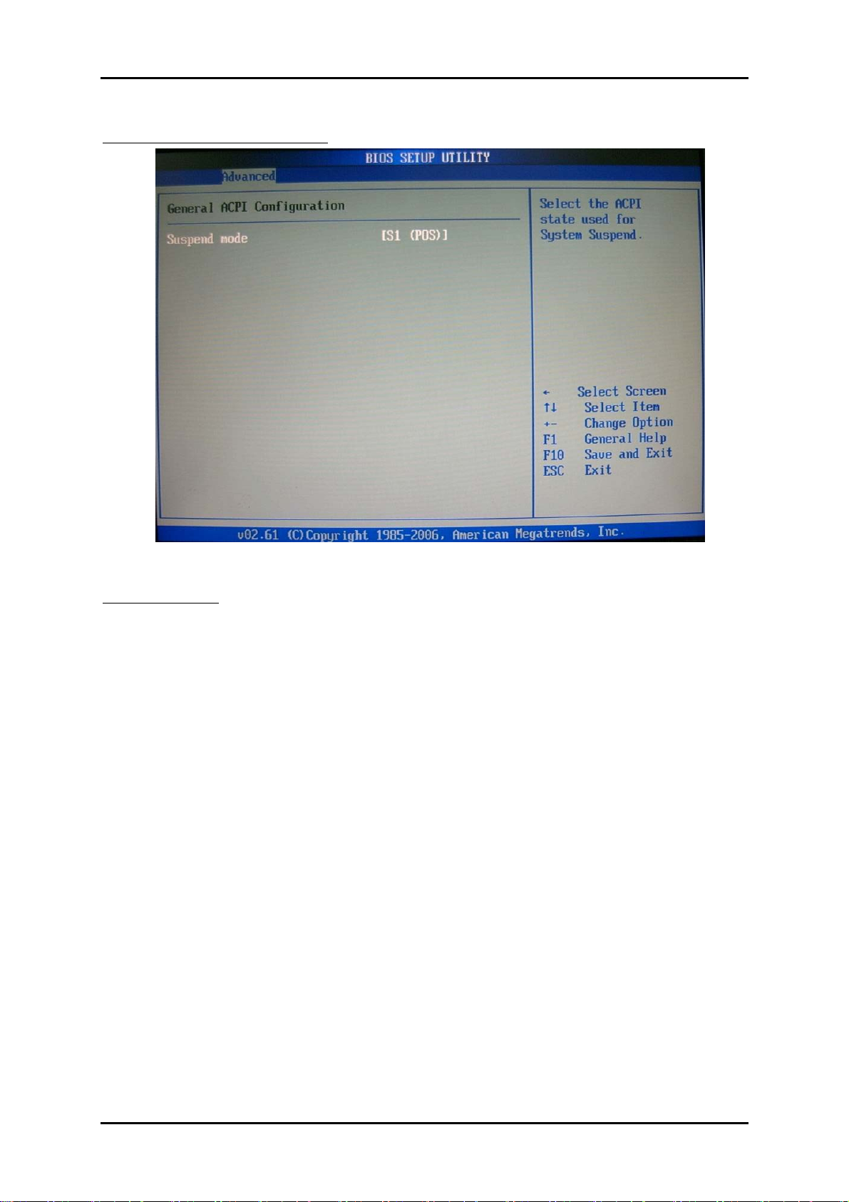
General ACPI Configuration
Suspend mode
This item specifies the power saving modes for ACPI function. If your operating
system supports ACPI, you can choose to enter the Standby mode in S1 (POS) or S3
(STR) fashion through the setting of this field. Options are:
[S1 (POS)] The S1 sleep mode is a low power state. In this state, no system context
is lost (CPU or chipset) and hardware maintains all system contexts.
[S3 (STR)] The S3 sleep mode is a lower power state where the information of system
configuration and open applications/ files is saved to main memory
that remains powered while most other hardware components turn
off to save energy. The information stored in memory will be used to restore
the system when a “wake up” event occurs.
RUBY-9719VG2AR User’s Manual 4-10
Page 37
BIOS Setup Information
www.ipc2u.ru www.ipc2u.de www.sovio.com Date: 01/07/2016
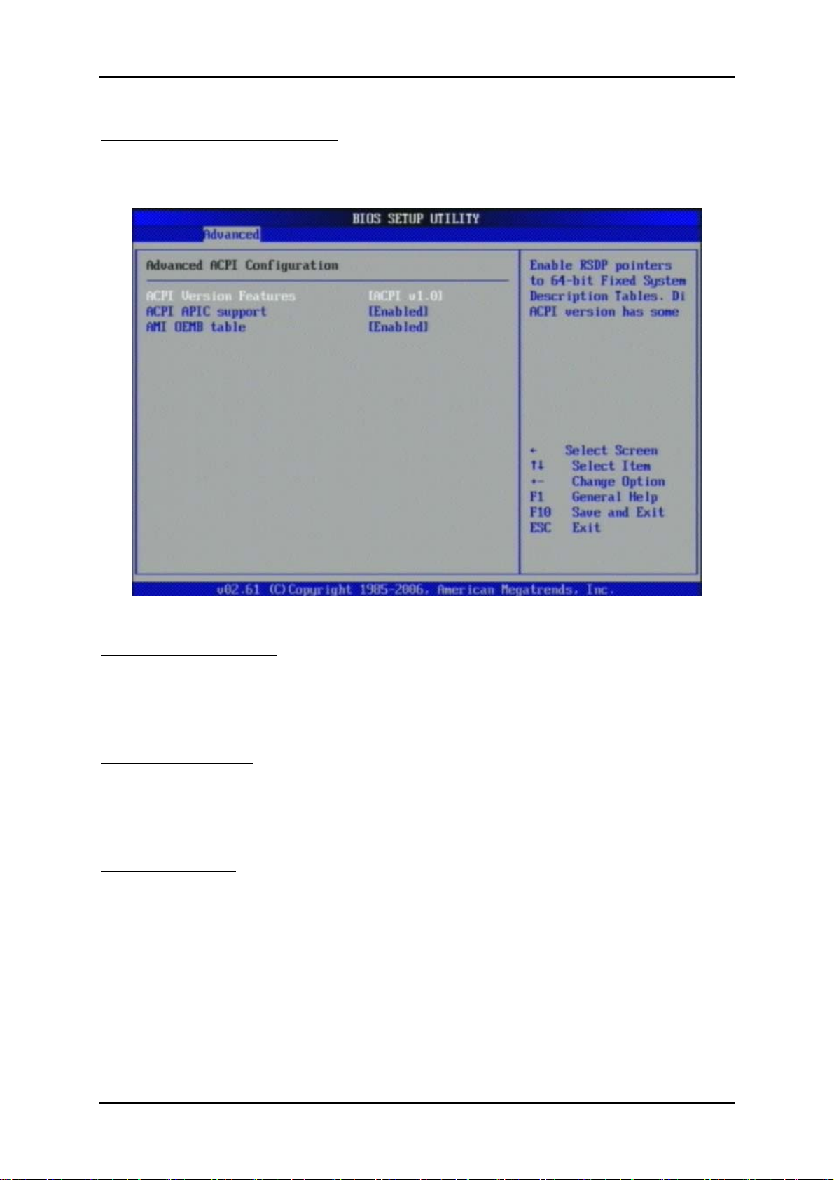
Advanced ACPI Configuration
Advanced ACPI Configuration settings, Use this section to configure additional
ACPI options.
ACPI Version Features
Enable RSDP pointers to 64-bit Fixed System Description Tables.
The choice: ACPI v1.0 / ACPI v2.0 / ACPI v3.0.
ACPI APIC support
Include ACPI APIC table pointer to RSDT pointer list.
The choice: Disabled, Enabled.
AMI OEMB table
Include OEMB table pointer to R(X) SDT pointer list.
The choice: Disabled, Enabled.
RUBY-9719VG2AR User’s Manual 4-11
Page 38
BIOS Setup Information
www.ipc2u.ru www.ipc2u.de www.sovio.com Date: 01/07/2016
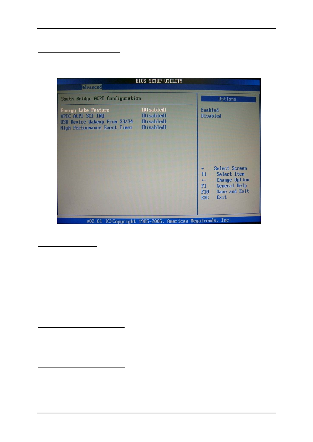
Chipset ACPI Configuration
Chipset ACPI related Configuration settings, Use this section to configure
additional ACPI options.
Energy Lake Feature
Select the ACPI state used for System Suspend.
The choice: Disabled, Enabled.
APIC ACPI SCI IRQ
Enable / Disable APIC ACPI SCI IRQ.
The choice: Disabled, Enabled.
USB Device Wake From S3/S4
Enable / Disable USB device Wake from S3/S4 mode.
The choice: Disabled, Enabled.
High Performance Event Time
The choice: Disabled, Enabled.
RUBY-9719VG2AR User’s Manual 4-12
Page 39
BIOS Setup Information
www.ipc2u.ru www.ipc2u.de www.sovio.com Date: 01/07/2016
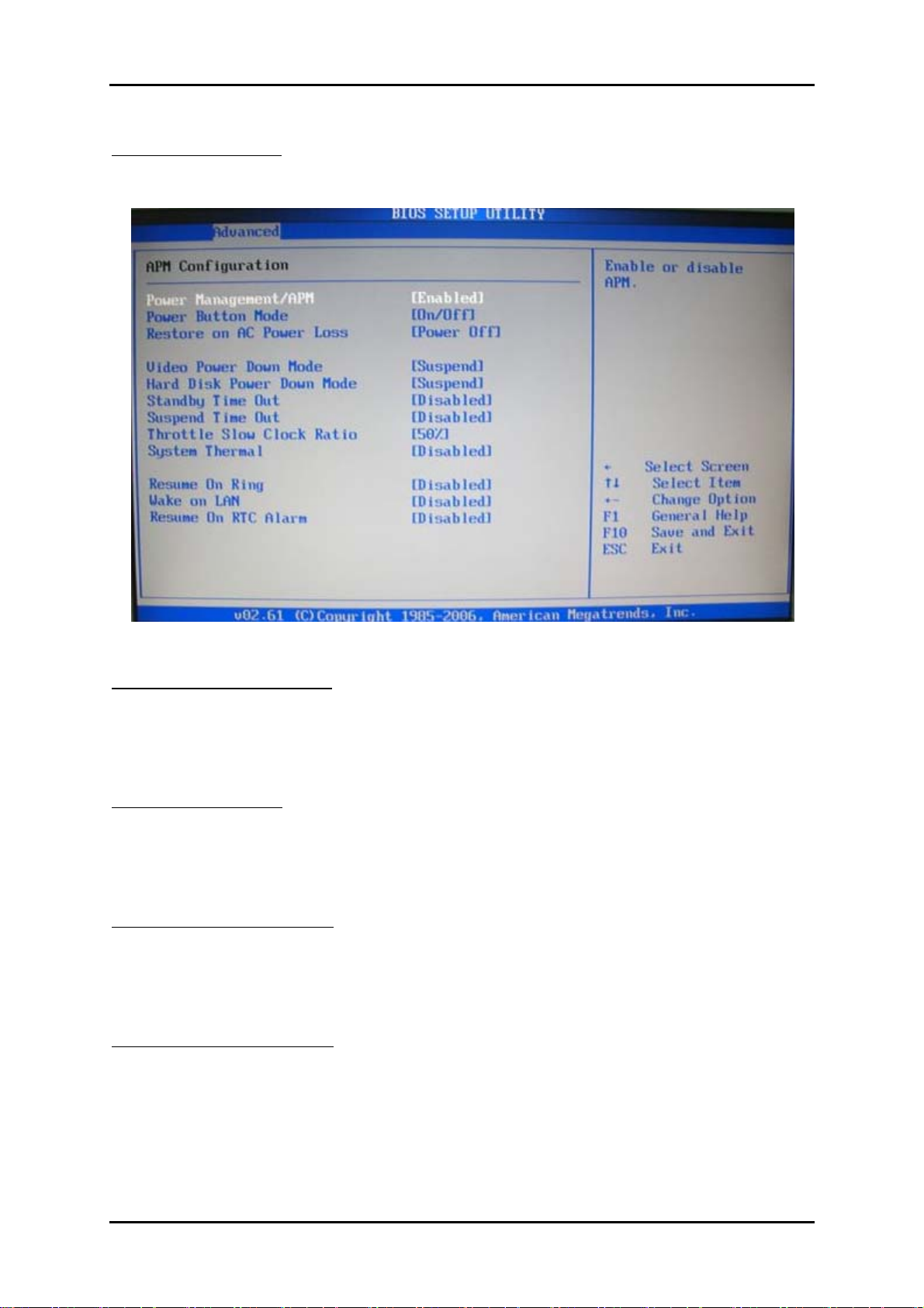
APM Configuration
Select for APM Configuration.
Power Management/APM
Enabled or Disable APM Mode.
The choice: Disabled, Enabled.
Power Button Mode
Go into On/Off or Suspend when Power button is pressed.
The choice: On/Off, Suspend.
Video Power Down Mode
Select AC Power loss mode
The choice: Power off/Power on /Last State
Video Power Down Mode
Select Power Down video in Suspend or Standby Mode.
The choice: Disabled, Suspend.
RUBY-9719VG2AR User’s Manual 4-13
Page 40

BIOS Setup Information
www.ipc2u.ru www.ipc2u.de www.sovio.com Date: 01/07/2016
Hard Disk Power Down Mode
Select Power Down Hard Disk in Suspend or Standby Mode.
The choice: Disabled, Enabled.
Suspend Time Out
Go into Suspend in the specified Time.
The choice: Disabled, 1 Min, 2 Min, 4 Min, 8 Min, 10 Min, 20 Min, 30 Min, 40 Min,
50Min, and 60 Min.
Resume On Ring
Disable/Enable RI to generate a wake event.
The choice: Disabled, Enabled.
Resume On LAN
Disable/Enable LAN to generate a wake event.
The choice: Disabled, Enabled.
Resume On RTC Alarm
Disable/Enable RTC to generate a wake event.
The choice: Disabled, Enabled.
RUBY-9719VG2AR User’s Manual 4-14
Page 41
BIOS Setup Information
www.ipc2u.ru www.ipc2u.de www.sovio.com Date: 01/07/2016
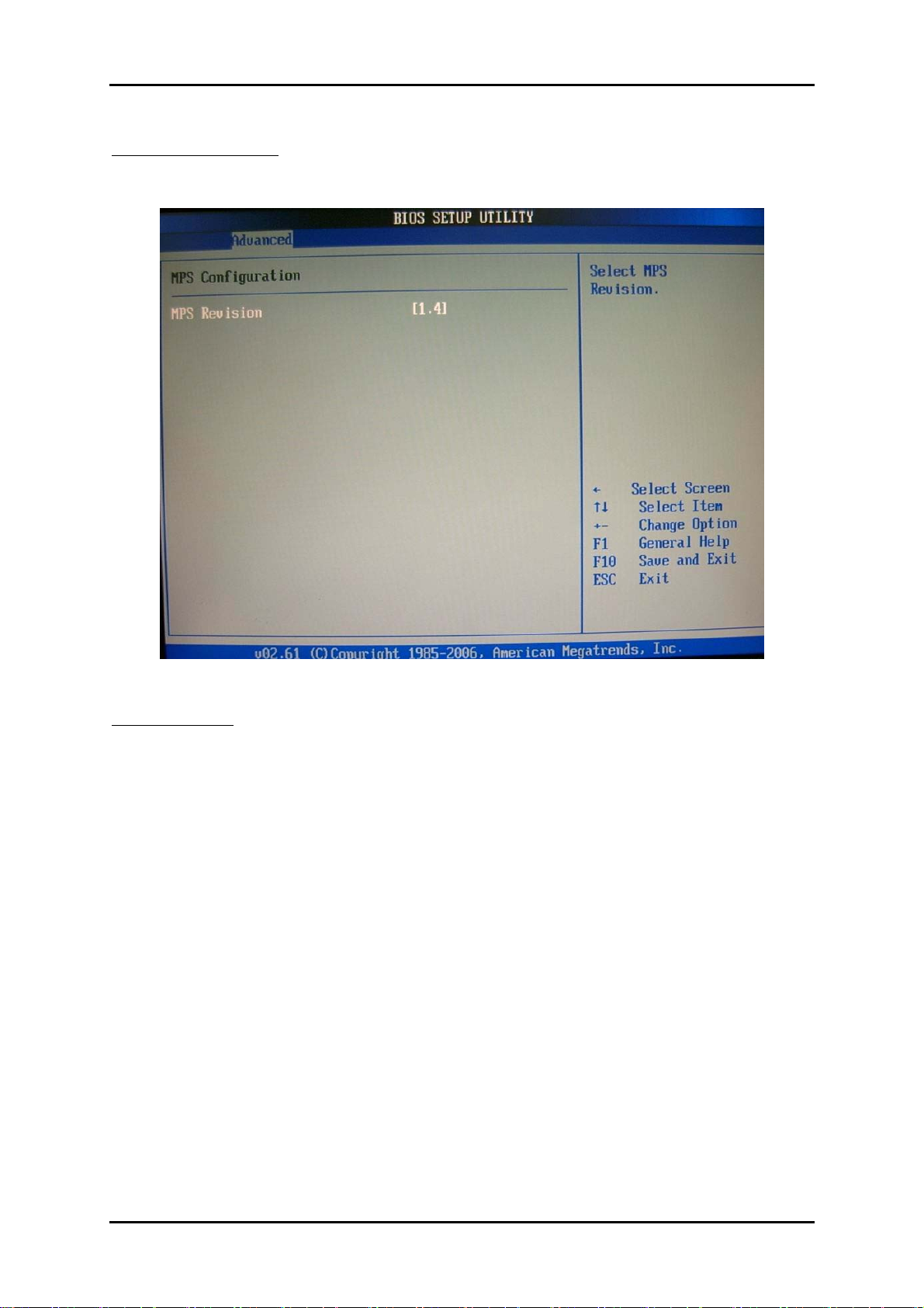
MPS Configuration
Configure the Multi-Processor Table.
MPS Revision
This field allows you to select which MPS (Multi-Processor Specification) version to
be used for the operating system. You need to select the MPS version supported by
your operating system. To find out which version to use, consult the vendor of your
operating system.
The choice: 1.1, 1.4.
RUBY-9719VG2AR User’s Manual 4-15
Page 42
BIOS Setup Information
www.ipc2u.ru www.ipc2u.de www.sovio.com Date: 01/07/2016
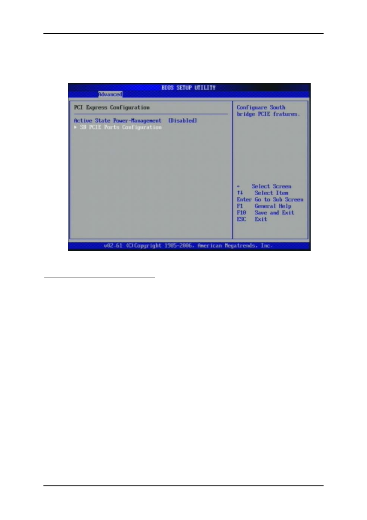
PCI Express Configuration
Configure PCI Express Support.
Active State Power-Management
PCI Express L0s and L1 link power states.
The choice: Disabled, Enabled.
SB PCIE Ports Configuration
Configuare South bridge PCIE fratures
The choice: Default is Auto
RUBY-9719VG2AR User’s Manual 4-16
Page 43
BIOS Setup Information
www.ipc2u.ru www.ipc2u.de www.sovio.com Date: 01/07/2016
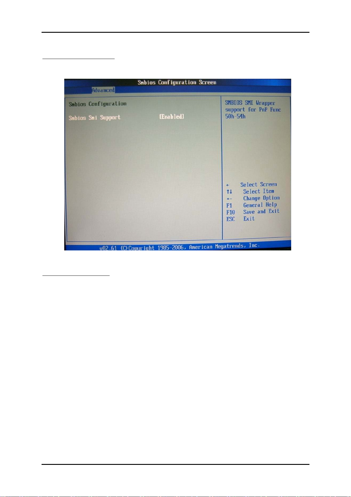
Smbios Configuration
SMBIOS Configuration Menu.
Smbios Smi Support
SMBIOS SMI Wrapper support for PnP Func 50h-54h.
The choice: Disabled, Enabled.
RUBY-9719VG2AR User’s Manual 4-17
Page 44
BIOS Setup Information
www.ipc2u.ru www.ipc2u.de www.sovio.com Date: 01/07/2016
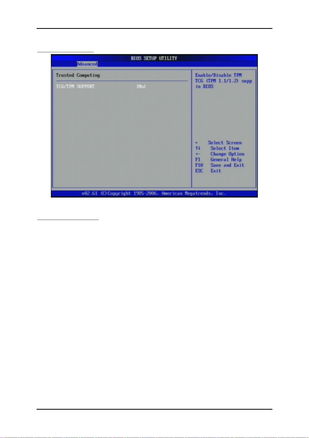
Trusted Computing
TCG/TPM SUPPORT
Enable/Disable TPM and TGC(TPM 1.1/1.2)
The choice: YES,NO
RUBY-9719VG2AR User’s Manual 4-18
Page 45
BIOS Setup Information
www.ipc2u.ru www.ipc2u.de www.sovio.com Date: 01/07/2016
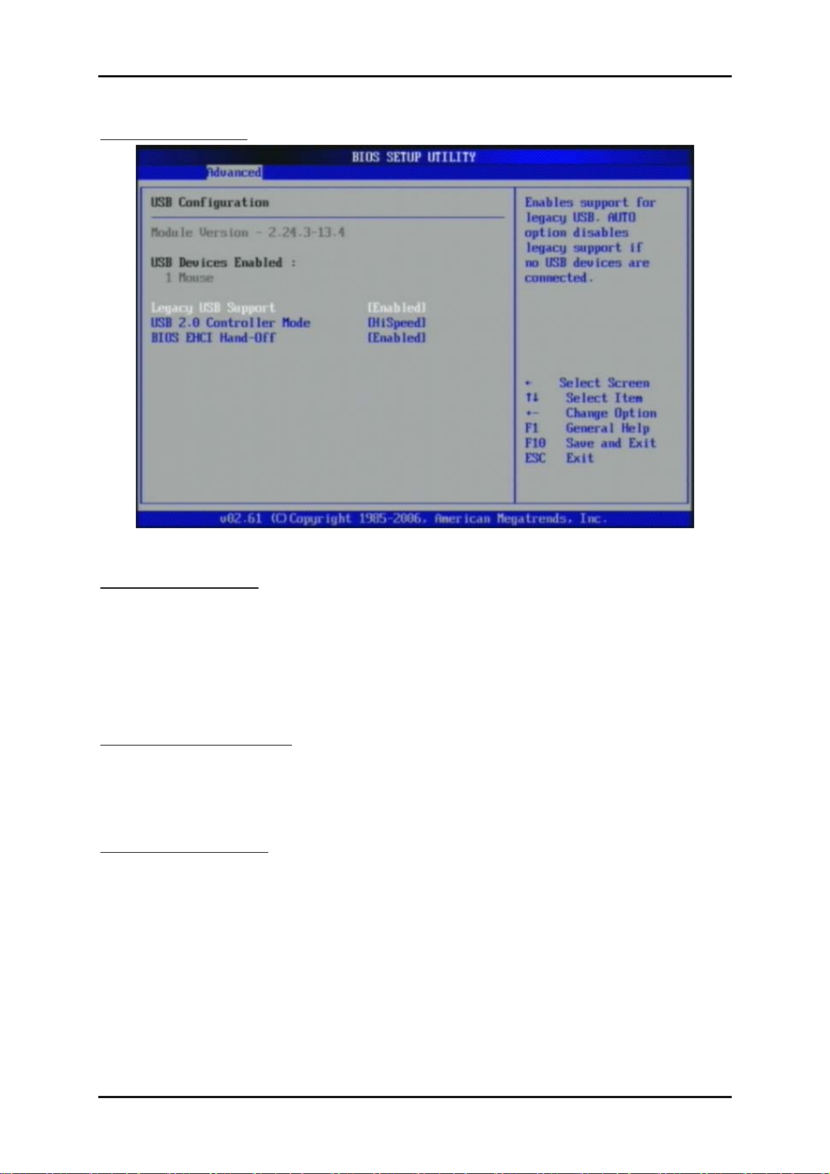
USB Configuration
Legacy USB Support
Set to [Enabled] if you need to use any USB 1.1/2.0 device in the operating system
that does not support or have any USB 1.1/2.0 driver installed, such as DOS and SCO
Unix.
The choice: Disabled, Enabled, Auto.
USB 2.0 Controller Mode
This setting specifies the operation mode of the onboard USB 2.0 controller.
The choice: FullSpeed, HiSpeed.
BIOS EHCI Hand-Off
This is a workaround for OSes without EHCI hand-off support. The EHCI ownership
change should claim by EHCI driver.
The choice: Disabled, Enabled.
RUBY-9719VG2AR User’s Manual 4-19
Page 46
BIOS Setup Information
www.ipc2u.ru www.ipc2u.de www.sovio.com Date: 01/07/2016
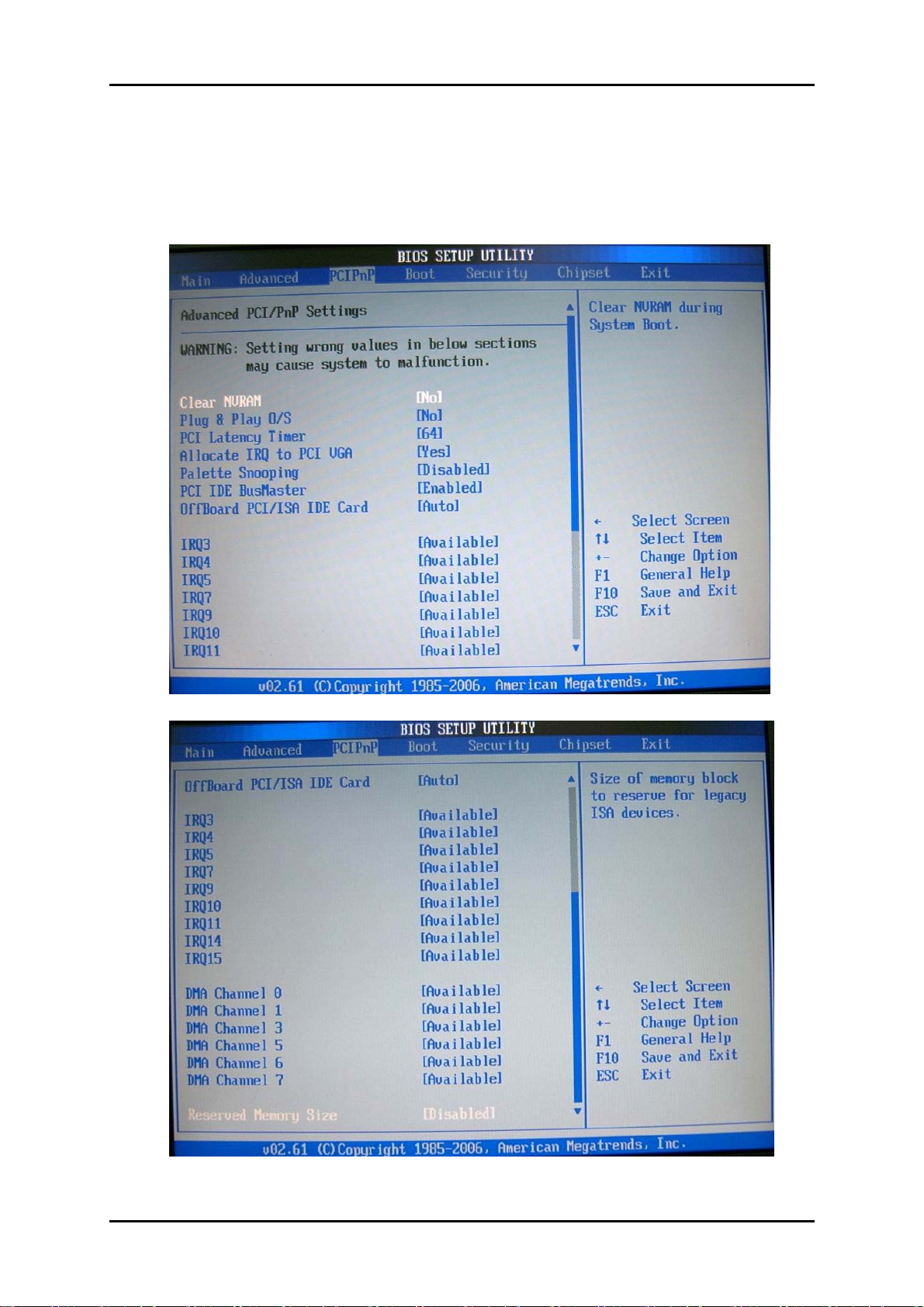
4.4 PCIPnP
Advanced PCI/PnP setting wrong values in below sections may cause system to
malfunction.
RUBY-9719VG2AR User’s Manual 4-20
Page 47

BIOS Setup Information
www.ipc2u.ru www.ipc2u.de www.sovio.com Date: 01/07/2016
Clear NVRAM
Clear NVRAM during System Boot.
The choice: No, Yes.
Plug & Play O/S
No: lets the BIOS configure all the devices in the system.
Yes: lets the operating system configure Plug and Play (PnP) devices not required for
boot if your system has a Plug and Play operating system.
The choice: No, Yes.
PCI Latency Timer
Select value in units of PCI clocks for PCI device latency timer register.
The choice: 32, 64, 96, 128, 160, 192, 224, 248.
Allocate IRQ to PCI VGA
Yes: Assigns IRQ to PCI VGA card if card requests an IRQ.
No: Does not assign IRQ to PCI VGA card even if card requests an IRQ.
The choice: No, Yes.
Palette Snooping
Enabled: informs the PCI devices that an ISA graphics device is installed in the
system so the card will function correctly.
The choice: Disabled, Enabled.
PCI IDE BusMaster
Enabled: Uses PCI bus mastering for reading / writing to IDE drives.
The choice: Disabled, Enabled.
OffBoard PCI/ISA IDE Card
Some PCI IDE cards may require this to be set to the PCI slot number that is holding
the card. AUTO: Works for most PCI IDE cards
The choice: Auto, PCI Slot1, PCI Slot2, PCI Slot3, PCI Slot4, PCI Slot5, PCI Slot6.
RUBY-9719VG2AR User’s Manual 4-21
Page 48
BIOS Setup Information
www.ipc2u.ru www.ipc2u.de www.sovio.com Date: 01/07/2016
IRQ 3 / IRQ 4 / IRQ5 / IRQ7 / IRQ 9 / IRQ 10 / IRQ 11 / IRQ 14 / IRQ 15
Available: Specified IRQ is available to be used by PCI/PnP devices.
Reserved: Specified IRQ is reserved for used by Legacy ISA devices.
The choice: Available, Reserved.
DMA Channel 0 / DMA Channel 1 / DMA Channel 3 / DMA Channel 5 / DMA
Channel 6 / DMA Channel 7
Available: Specified DMA is available to be used by PCI/PnP devices. Reserved:
Specified DMA is reserved for use by Legacy ISA devices.
The choice: Available, Reserved.
Reserved Memory Size
Select Size of memory block to reserve for legacy ISA devices.
The choice: Disabled, 16K, 32K, 64K.
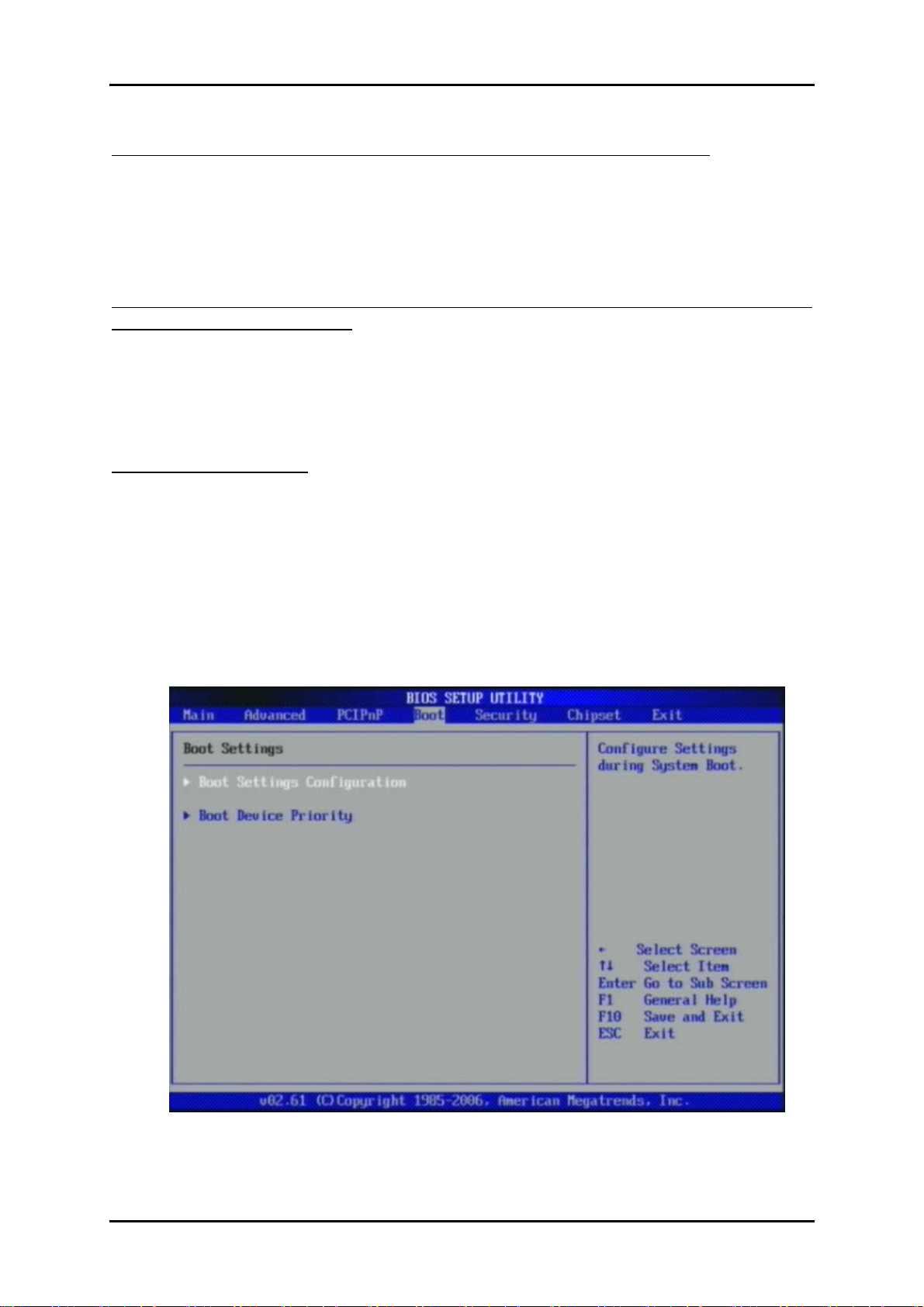
4.5 Boot
Use this menu to specify the priority of boot devices.
RUBY-9719VG2AR User’s Manual 4-22
Page 49
BIOS Setup Information
www.ipc2u.ru www.ipc2u.de www.sovio.com Date: 01/07/2016
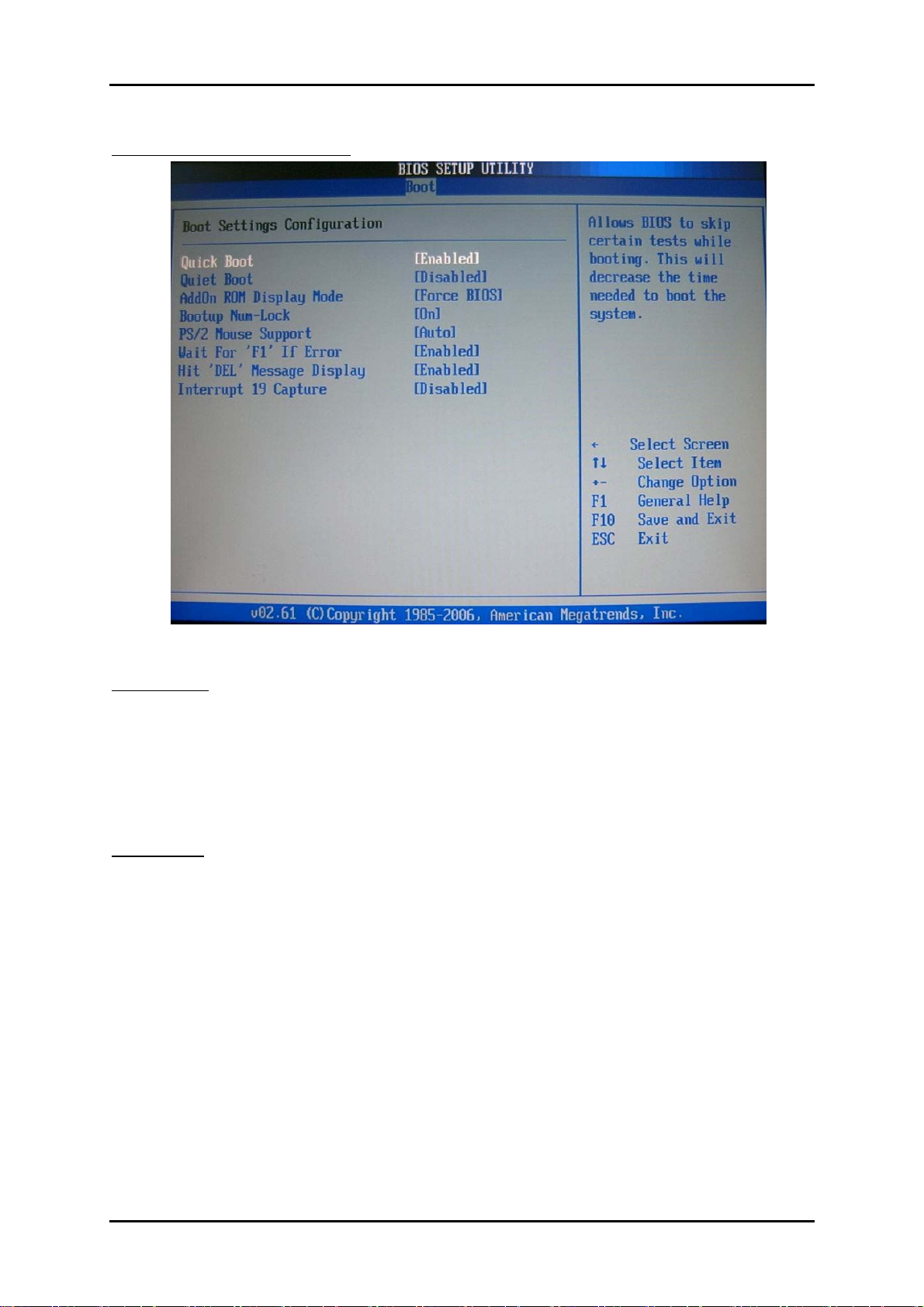
Boot Settings Configuration
Quick Boot
Enabling this setting will cause the BIOS power-on self test routine to skip some
of
its tests during boot up for faster system boot.
The choice: Disabled, Enabled.
Quiet Boot
This BIOS feature determines if the BIOS should hide the normal POST
messages with the motherboard or system manufacturer's full-screen logo. When it
is enabled, the BIOS will display the full-screen logo during the boot-up sequence,
hiding normal POST messages. When it is disabled, the BIOS will display the
normal POST messages, instead of the full-screen logo.
Please note that enabling this BIOS feature often adds 2-3 seconds of delay to the
booting sequence. This delay ensures that the logo is displayed for a sufficient
amount of time. Therefore, it is recommended that you disable this BIOS feature
for
a faster boot-up time.
The choice: Disabled, Enabled.
RUBY-9719VG2AR User’s Manual 4-23
Page 50

BIOS Setup Information
www.ipc2u.ru www.ipc2u.de www.sovio.com Date: 01/07/2016
AddOn ROM Display Mode
This item is used to determine the display mode when an optional ROM is initialized
during POST. When set to [Force BIOS], the display mode used by AMI BIOS is
used. Select [Keep Current] if you want to use the display mode of optional ROM.
The choice: Force BIOS, Keep Current.
Bootup Num-Lock
This setting is to set the Num Lock status when the system is powered on.
Setting to [On] will turn on the Num Lock key when the system is powered on.
Setting to [Off] will allow users to use the arrow keys on the numeric keypad.
The choice: Off, On.
PS/2 Mouse support
Select [Enabled] if you need to use a PS/2-interfaced mouse in the operating system.
The choice: Disabled, Enabled, Auto.
Wait For ‘F1’ If Error
When this setting is set to [Enabled] and the boot sequence encounters an error, it
asks you to press F1. If disabled, the system continues to boot without waiting
for you to press any keys.
The choice: Disabled, Enabled.
Hit ‘DEL’ Message Display
Set this option to [Disabled] to prevent the message as follows:
Hit Del if you want to run setup
It will prevent the message from appearing on the first BIOS screen when the
computer boots. Set it to [Enabled] when you want to run the BIOS Setup Utility.
The choice: Disabled, Enabled.
Interrupt 19 Capture
Interrupt 19 is the software interrupt that handles the boot disk function. When
enabled, this BIOS feature allows the ROM BIOS of these host adaptors to
"capture" Interrupt 19 during the boot process so that drives attached to these
adaptors can function as bootable disks. In addition, it allows you to gain access to
the host adaptor's ROM setup utility, if one is available.
RUBY-9719VG2AR User’s Manual 4-24
Page 51
BIOS Setup Information
www.ipc2u.ru www.ipc2u.de www.sovio.com Date: 01/07/2016
When disabled, the ROM BIOS of these host adaptors will not be able to "cap ture"
Interrupt 19. Therefore, you will not be able to boot operating systems from any
bootable disks attached to these host adaptors. Nor will you be able to gain access to
their ROM setup utilities.
The choice: Disabled, Enabled.
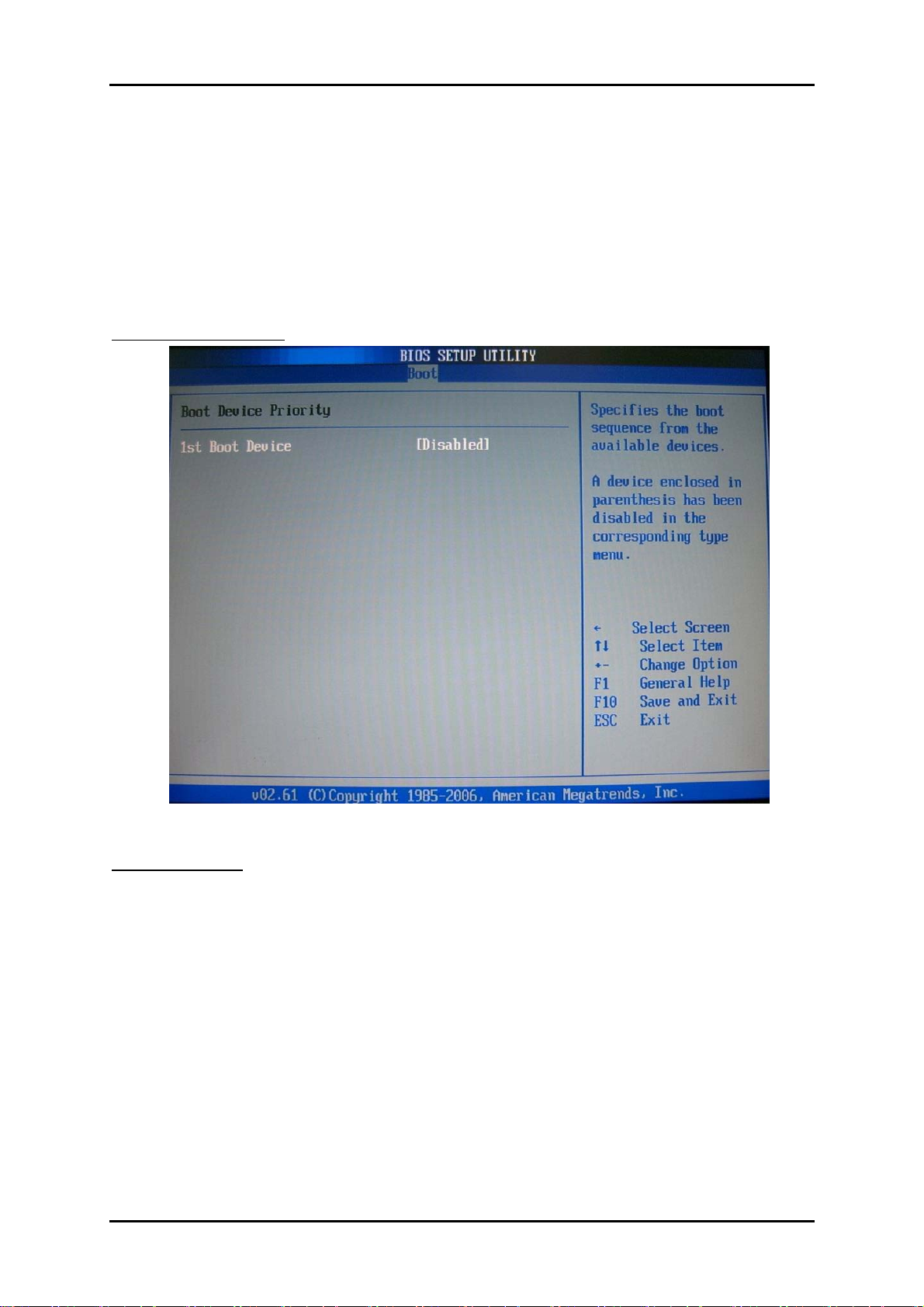
Boot Device Priority
1st Boot Device
The items allow you to set the sequence of boot devices where BIOS attempts to load
the disk operating system. First press <Enter> to enter the sub-menu. Then you
may
press <+ >, <-> or
use the arrow keys (↑↓) to select the desired device, then
<PageUp>, <PageDown> key to move it up/down in the
priority list.
The choice: (Removable Dev.), Disabled.
RUBY-9719VG2AR User’s Manual 4-25
Page 52
BIOS Setup Information
www.ipc2u.ru www.ipc2u.de www.sovio.com Date: 01/07/2016
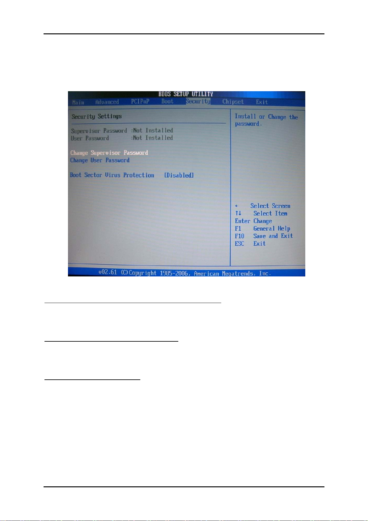
4.6 Security
Use this menu to set supervisor and user passwords.
Supervisor Password / Change Supervisor Password
Supervisor Password controls access to the BIOS Setup utility. These settings allow
you to set or change the supervisor password.
User Password / Change User Password
User Password controls access to the system at boot. These settings allow you to set
or change the user password.
Boot Sector Virus Protection
Boot Sector Virus Protection.
The choice: Disabled, Enabled.
RUBY-9719VG2AR User’s Manual 4-26
Page 53
BIOS Setup Information
www.ipc2u.ru www.ipc2u.de www.sovio.com Date: 01/07/2016
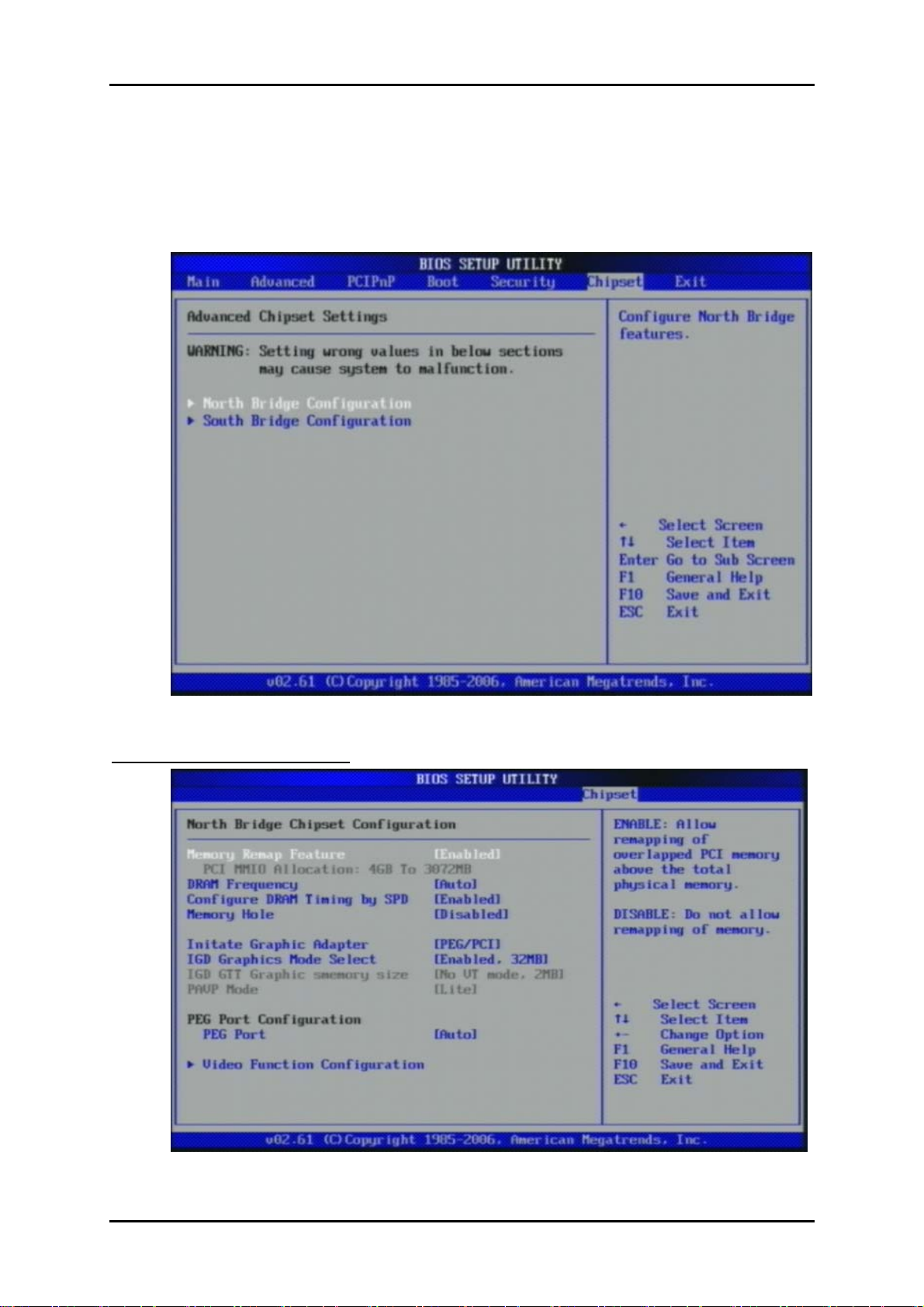
4.7 Chipset
This menu controls the advanced features of the onboard Northbridge and
Southbridge.
North Bridge Configuration
RUBY-9719VG2AR User’s Manual 4-27
Page 54

BIOS Setup Information
www.ipc2u.ru www.ipc2u.de www.sovio.com Date: 01/07/2016
Memory Remap Feature
Enabled: Allow remapping of overlapped PCI memory above the total physical
memory. Disabled: Do not allow remapping of memory.
The choice: Disabled, Enabled.
DRAM Frequency
Users are recommended to use Auto for memory frequency selection.
The choice: Auto, 533, 667, 800, 1067,1333 MHz.
Configure DRAM Timing by SPD
This option provides DRAM plug-and-play support by serial presence detect (SPD)
mechanism via the system management bus (SMBUS) interface.
The choice: Disabled, Enabled.
Memory Hole
In order to improve performance, certain space in memory is reserved for ISA
cards. This memory must be mapped into the memory space below 16MB.
The choice: Disabled, 15MB-16MB.
Initiate Graphic Adapter
Select which graphics controller to use as the primary boot device.
The choice: IGD, PCI/IGD, PCI/PEG, PEG/IGD, PEG/PCI.
Internal Graphics Mode Select
Select the amount of system memory used by the internal graphics device.
The choice: Enabled, 1MB, Enabled, 8MB.
PEG Port
This setting allows you to select whether to use the on-chip graphics processor or
the PCI Express card. When set to [Auto], the BIOS checks to see if a PCI Express
graphics card is installed. If it detects that a PCI Express graphics card is present, the
motherboard boots up using that card. Otherwise, it defaults to the onboard graphics
processor.
The choice: Auto, Disabled.
RUBY-9719VG2AR User’s Manual 4-28
Page 55
BIOS Setup Information
www.ipc2u.ru www.ipc2u.de www.sovio.com Date: 01/07/2016
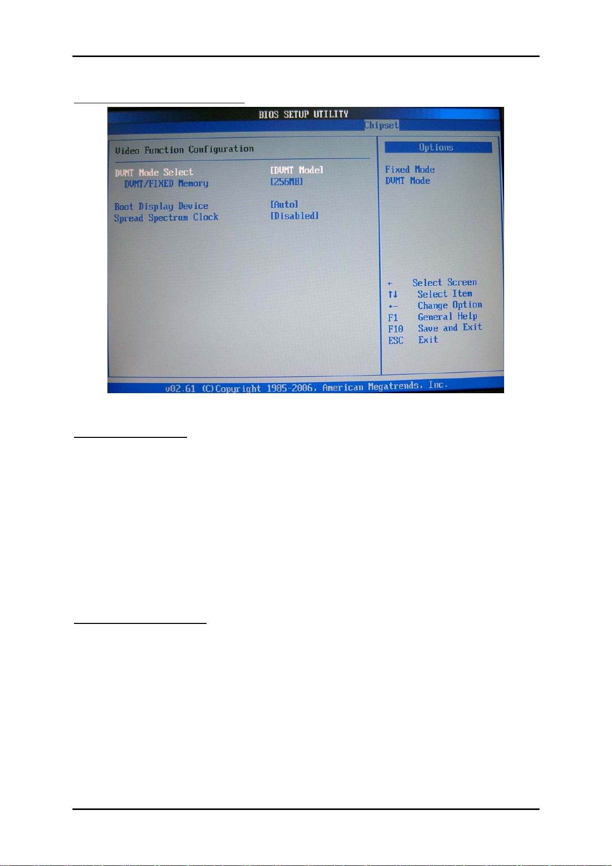
Video Function Configuration
DVMT Mode Select
Intel's Dynamic Video Memory Technology (DVMT) allows the system to
dynamically allocate memory resources according to the demands of the system at
any point in time. The key idea in DVMT is to improve the efficiency of the memory
allocated to either system or graphics processor.
It is recommended that you set this BIOS feature to DVMT Mode for maximum
performance. Setting it to DVMT Mode ensures that system memory is dynamically
allocated for optimal balance between graphics and system performance.
The choice: Fixed Mode, DVMT Mode.
DVMT/FIXED Memory
When set to DVMT/FIXED Mode, the graphics driver will allocate a fixed amount
of memory as dedicated graphics memory, as well as allow more system memory to
be dynamically allocated between the graphics processor and the operating system.
The choice: 128MB, 256MB.
RUBY-9719VG2AR User’s Manual 4-29
Page 56
BIOS Setup Information
www.ipc2u.ru www.ipc2u.de www.sovio.com Date: 01/07/2016
Boot Display Device
Use the field to select the type of device you want to use as the display(s) of the
system.
The choice: Auto, CRT on Port 0.
Spread Spectrum Clock
The choice: Disabled, Enabled.
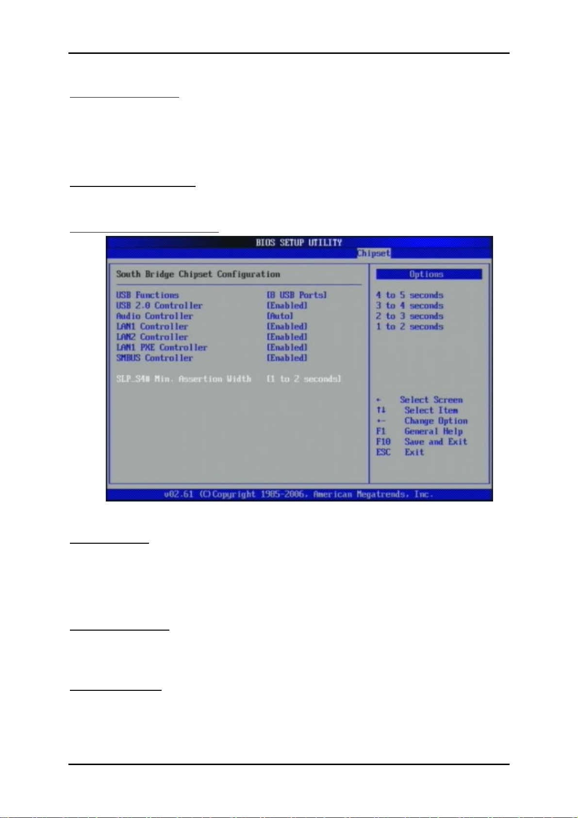
South Bridge Configuration
USB Functions
This setting specifies the function of the onboard USB controller.
The choice: Disabled, 2 USB Ports, 4 USB Ports, 6 USB Ports, 8 USB Ports, 10
USB Ports, 12 USB Ports.
USB 2.0 Controller
Set to [Enabled] if you need to use any USB 2.0 device in the operating system that
does not support or have any USB 2.0 driver installed, such as DOS and SCO Unix.
Audio Controller
This setting Enable the onboard Audio controller.
RUBY-9719VG2AR User’s Manual 4-30
Page 57
BIOS Setup Information
www.ipc2u.ru www.ipc2u.de www.sovio.com Date: 01/07/2016
LAN1 Controller
This setting Enable the onboard Ethernet controller.
LAN2 Controller
This setting Enable the onboard Audio controller.
LAN1 PXE Controller
When [Enabled], the BIOS attempts to boot from a LAN boot image before it
attempts to boot from a local storage device.
The choice: Disabled, Enabled.
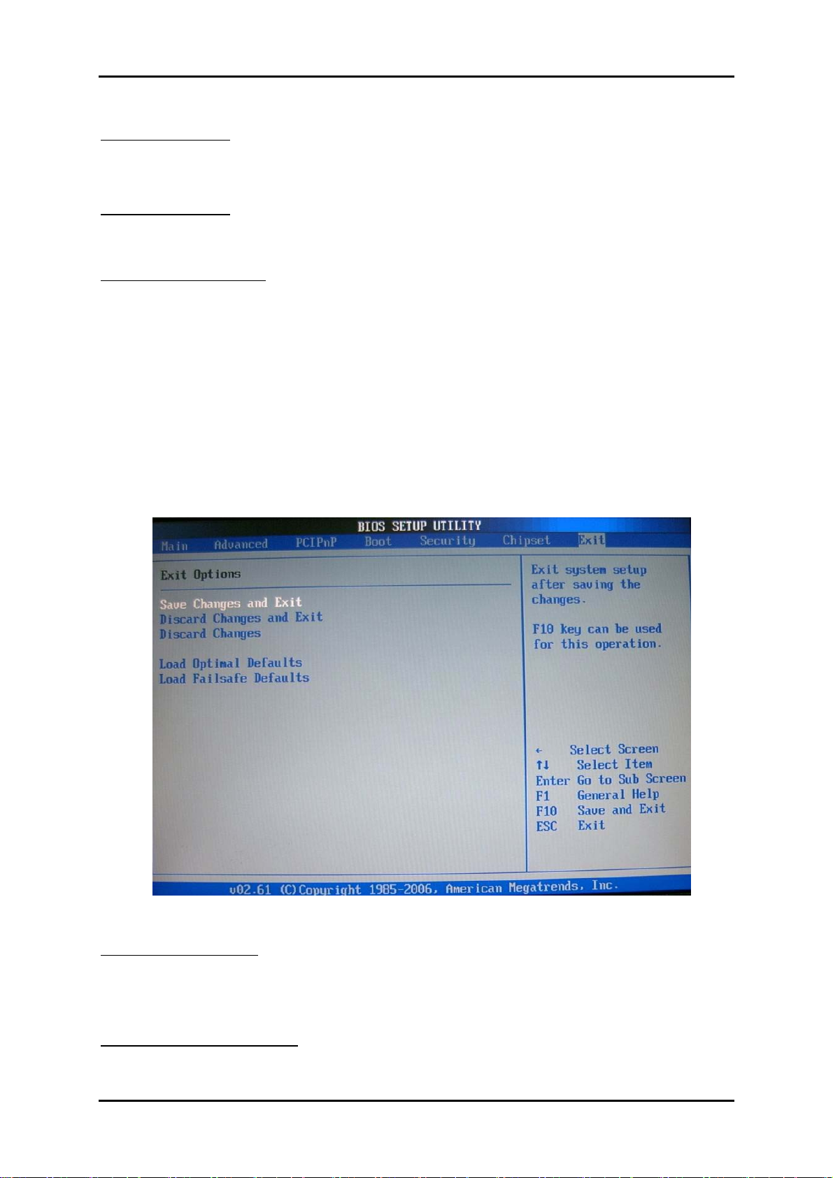
4.8 Exit
This menu allows you to load the BIOS default values or factory default settings into
the BIOS and exit the BIOS setup utility with or without changes.
Exit Saving Changes
Exit System Setup and save your changes to CMOS. Pressing <Enter> on this item
asks for confirmation: Save changes to CMOS and exit the Setup Utility.
Discard Changes and Exit
Abandon all changes and exit the Setup Utility.
RUBY-9719VG2AR User’s Manual 4-31
Page 58
BIOS Setup Information
www.ipc2u.ru www.ipc2u.de www.sovio.com Date: 01/07/2016
Discard Changes
Abandon all changes and continue with the Setup Utility.
Load Optimal Defaults
Use this menu to load the default values set by the SBC manufacturer specifically for
optimal performance of the SBC.
Load Failsafe Defaults
Use this menu to load the default values set by the BIOS vendor for stable
system.
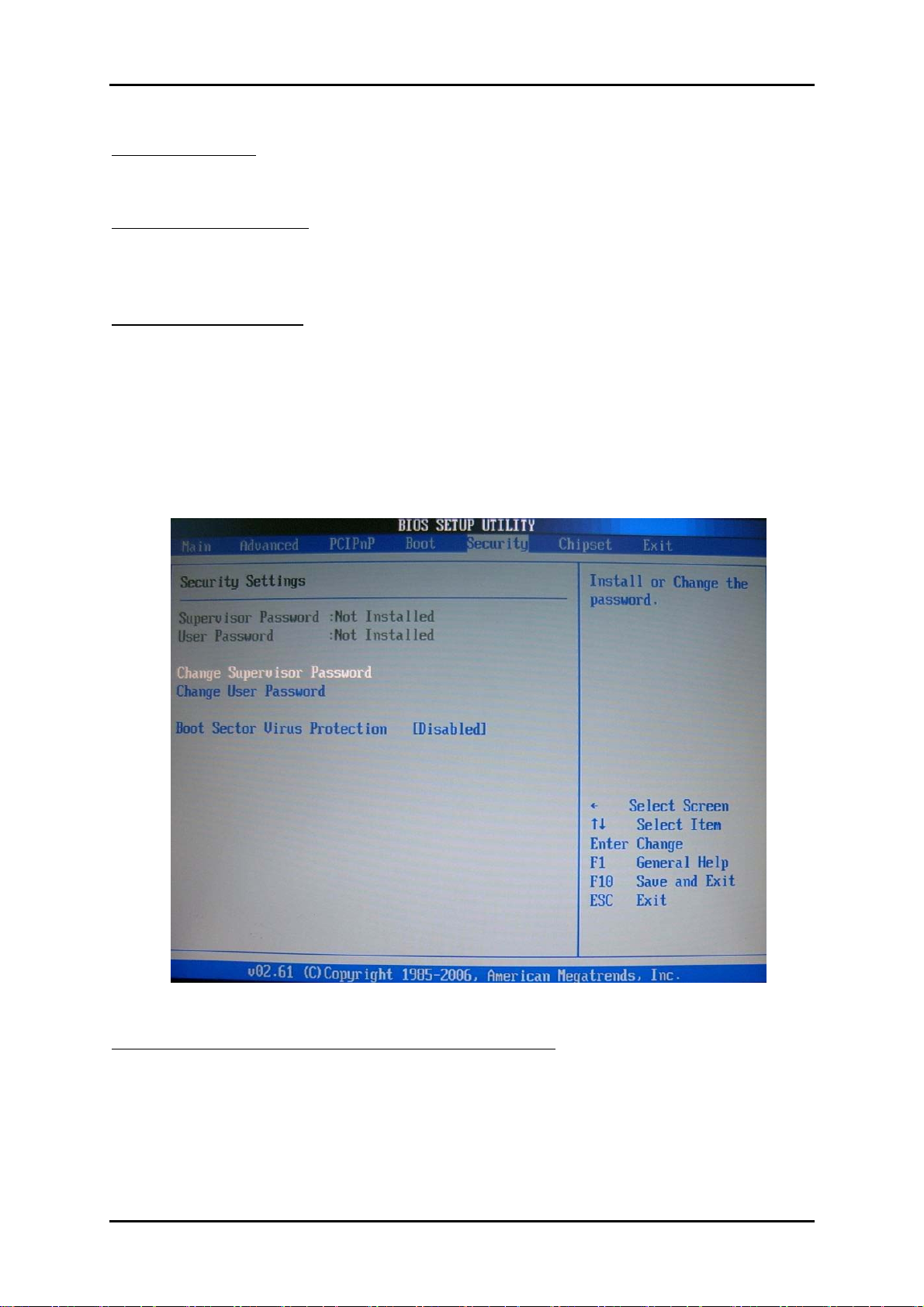
4.9 Security
Use this menu to set supervisor and user passwords.
Supervisor Password / Change Supervisor Password
Supervisor Password controls access to the BIOS Setup utility. These settings allow
you to set or change the supervisor password.
RUBY-9719VG2AR User’s Manual 4-32
Page 59
BIOS Setup Information
www.ipc2u.ru www.ipc2u.de www.sovio.com Date: 01/07/2016
User Password / Change User Password
User Password controls access to the system at boot. These settings allow you to set
or change the user password.
Boot Sector Virus Protection
Boot Sector Virus Protection.
The choice: Disabled, Enabled.
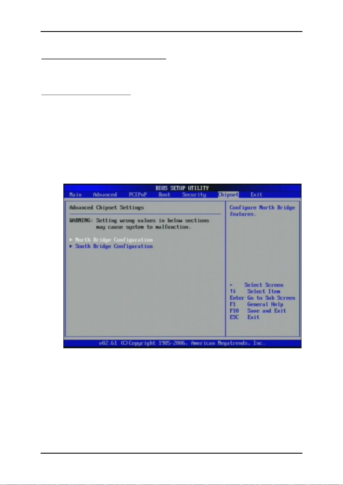
4.10 Chipset
This menu controls the advanced features of the onboard Northbridge and
Southbridge.
RUBY-9719VG2AR User’s Manual 4-33
Page 60
BIOS Setup Information
www.ipc2u.ru www.ipc2u.de www.sovio.com Date: 01/07/2016
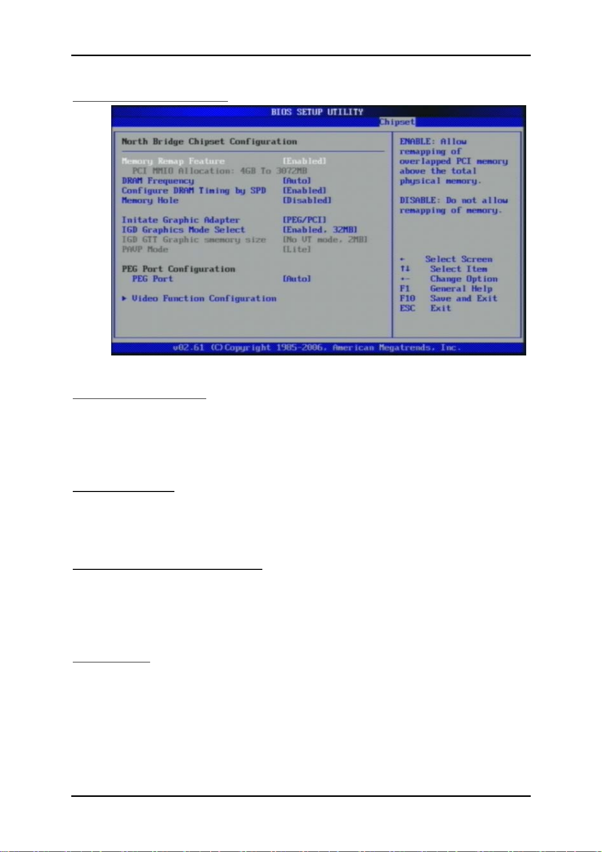
North Bridge Configuration
Memory Remap Feature
Enabled: Allow remapping of overlapped PCI memory above the total physical
memory. Disabled: Do not allow remapping of memory.
The choice: Disabled, Enabled.
DRAM Frequency
Users are recommended to use Auto for memory frequency selection.
The choice: Auto, 533, 667, 800, 1067,1333 MHz.
Configure DRAM Timing by SPD
This option provides DRAM plug-and-play support by serial presence detect (SPD)
mechanism via the system management bus (SMBUS) interface.
The choice: Disabled, Enabled.
Memory Hole
In order to improve performance, certain space in memory is reserved for ISA
cards. This memory must be mapped into the memory space below 16MB.
The choice: Disabled, 15MB-16MB.
RUBY-9719VG2AR User’s Manual 4-34
Page 61
BIOS Setup Information
www.ipc2u.ru www.ipc2u.de www.sovio.com Date: 01/07/2016
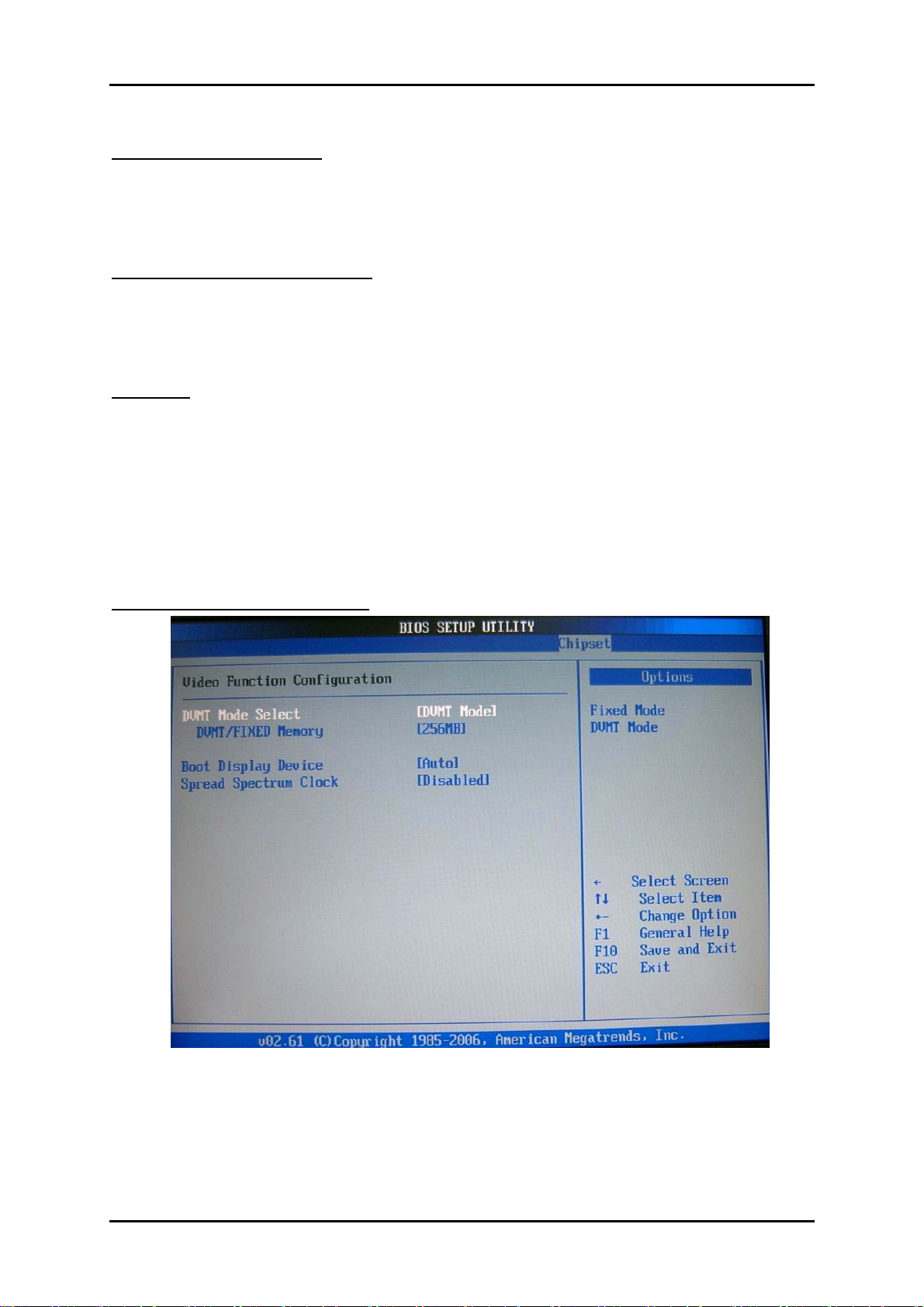
Initiate Graphic Adapter
Select which graphics controller to use as the primary boot device.
The choice: IGD, PCI/IGD, PCI/PEG, PEG/IGD, PEG/PCI.
Internal Graphics Mode Select
Select the amount of system memory used by the internal graphics device.
The choice: Enabled, 1MB, Enabled, 8MB.
PEG Port
This setting allows you to select whether to use the on-chip graphics processor or
the PCI Express card. When set to [Auto], the BIOS checks to see if a PCI
Express graphics card is installed. If it detects that a PCI Express graphics card is
present, the motherboard boots up using that card. Otherwise, it defaults to the
onboard graphics processor.
The choice: Auto, Disabled.
Video Function Configuration
RUBY-9719VG2AR User’s Manual 4-35
Page 62

BIOS Setup Information
www.ipc2u.ru www.ipc2u.de www.sovio.com Date: 01/07/2016
DVMT Mode Select
Intel's Dynamic Video Memory Technology (DVMT) allows the system to
dynamically allocate memory resources according to the demands of the system at
any point in time. The key idea in DVMT is to improve the efficiency of the memory
allocated to either system or graphics processor.
It is recommended that you set this BIOS feature to DVMT Mode for maximum
performance. Setting it to DVMT Mode ensures that system memory is dynamically
allocated for optimal balance between graphics and system performance.
The choice: Fixed Mode, DVMT Mode.
DVMT/FIXED Memory
When set to DVMT/FIXED Mode, the graphics driver will allocate a fixed amount
of memory as dedicated graphics memory, as well as allow more system memory to
be dynamically allocated between the graphics processor and the operating system.
The choice: 128MB, 256MB.
Boot Display Device
Use the field to select the type of device you want to use as the display(s)
of the system.
The choice: Auto, CRT on Port 0.
Spread Spectrum Clock
The choice: Disabled, Enabled.
RUBY-9719VG2AR User’s Manual 4-36
Page 63
BIOS Setup Information
www.ipc2u.ru www.ipc2u.de www.sovio.com Date: 01/07/2016
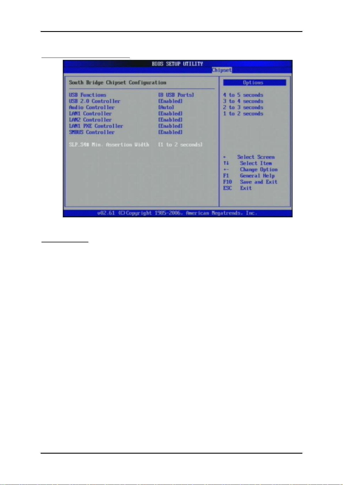
South Bridge Configuration
USB Functions
This setting specifies the function of the onboard USB controller.
The choice: Disabled, 2 USB Ports, 4 USB Ports, 6 USB Ports, 8 USB Ports, 10 USB
Ports, 12 USB Ports.
RUBY-9719VG2AR User’s Manual 4-37
Page 64
BIOS Setup Information
www.ipc2u.ru www.ipc2u.de www.sovio.com Date: 01/07/2016
USB 2.0 Controller
Set to [Enabled] if you need to use any USB 2.0 device in the operating system that
does not support or have any USB 2.0 driver installed, such as DOS and SCO Unix.
Audio Controller
This setting Enable the onboard Audio controller.
LAN1 Controller
This setting Enable the onboard Ethernet controller.
LAN2 Controller
This setting Enable the onboard Audio controller.
LAN1 PXE Controller
When [Enabled], the BIOS attempts to boot from a LAN boot image before it
attempts to boot from a local storage device.
The choice: Disabled, Enabled.
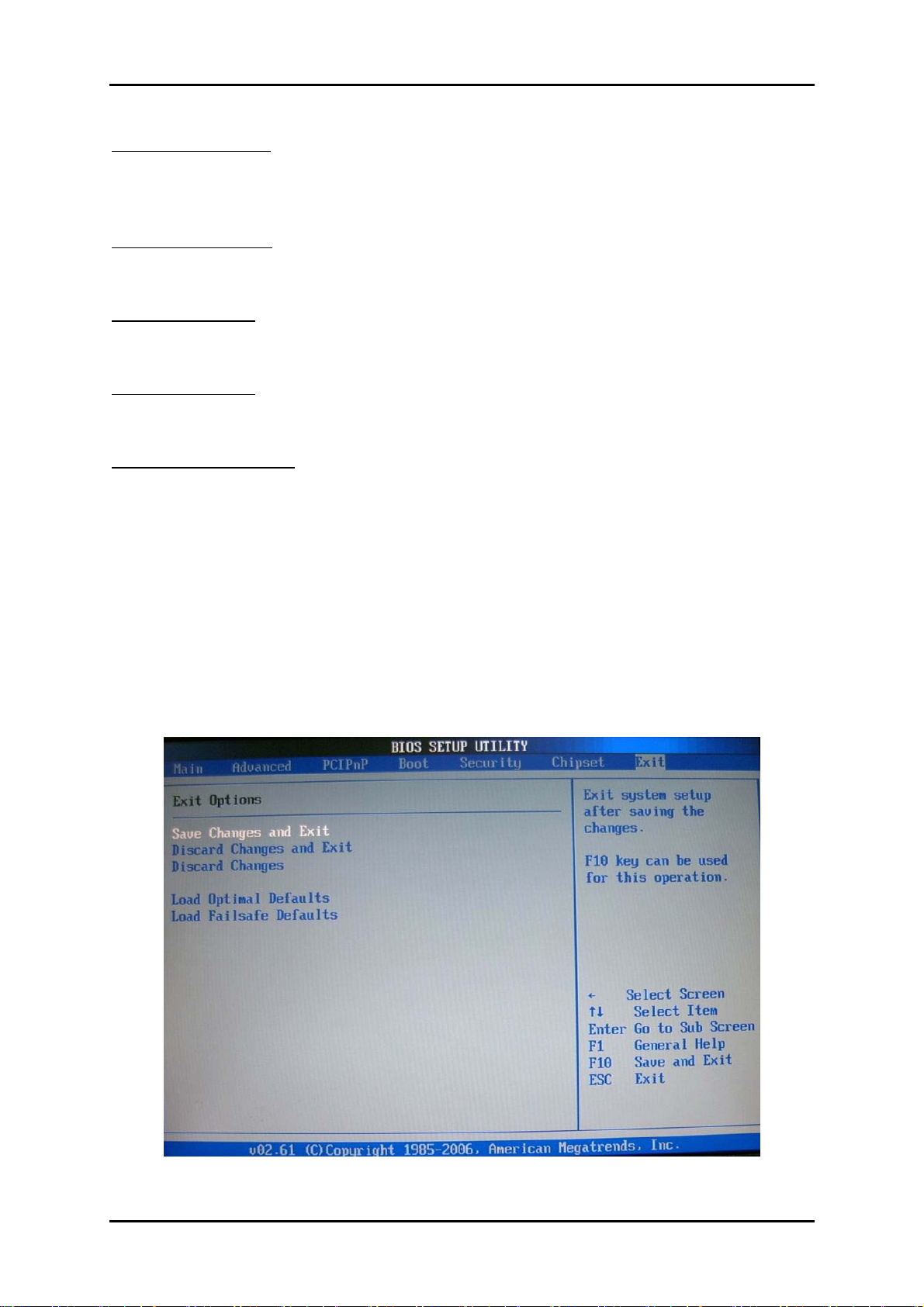
4.11 Exit
This menu allows you to load the BIOS default values or factory default settings into
the BIOS and exit the BIOS setup utility with or without changes.
RUBY-9719VG2AR User’s Manual 4-38
Page 65

BIOS Setup Information
www.ipc2u.ru www.ipc2u.de www.sovio.com Date: 01/07/2016
Exit Saving Changes
Exit System Setup and save your changes to CMOS. Pressing <Enter> on this item
asks for confirmation: Save changes to CMOS and exit the Setup Utility.
Discard Changes and Exit
Abandon all changes and exit the Setup Utility.
Discard Changes
Abandon all changes and continue with the Setup Utility.
Load Optimal Defaults
Use this menu to load the default values set by the SBC manufacturer specifically for
optimal performance of the SBC.
Load Failsafe Defaults
Use this menu to load the default values set by the BIOS vendor for stable
system.
RUBY-9719VG2AR User’s Manual 4-39
Page 66
Troubleshooting
www.ipc2u.ru www.ipc2u.de www.sovio.com Date: 01/07/2016
Chapter 5
Troubleshooting
This chapter provides a few useful tips to quickly get RUBY-9719VG2AR running
with success. As basic hardware installation has been addressed in Chapter 2, this
chapter will primarily focus on system integration issues, in terms of BIOS setting,
and OS diagnostics.
5.1 Hardware Quick Installation
P4 Power connector
The CPU supplementary Power Connector (J9) has to be connected to a system all
the time no matter using ATX mode. Otherwise, the system won’t boot up properly.
Serial ATA Hard Disk employment
Each Serial ATA channel can only connect to one SATA hard disk at a time; there
are total four connectors, J31,J32,J35,J36. The installation of Serial ATA is simpler
and easier than IDE, because SATA hard disk doesn’t require setting up Master and
Slave, which can reduce mistake of hardware installation. All you need to do is
to plug in two cables and enable SATA in System BIOS.
RUBY-9719VG2AR User’s Manual 5-1
Page 67

Troubleshooting
www.ipc2u.ru www.ipc2u.de www.sovio.com Date: 01/07/2016
5.2 BIOS Setting
It is assumed that users have correctly adopted modules and connected all the
devices cables required before turning on ATX power. CPU, CPU Fan, 240-pin DDR2
SDRAM, keyboard, mouse, floppy drive, IDE hard disk, printer, VGA connector,
device cables, ATX accessories or 12V 4-pin power cable are good examples that
deserve attention. With no assurance of properly and correctly accommodating these
modules and devices, it is very possible to encounter system failures that result in
malfunction of any device.
To make sure that you have a successful start with RUBY-9719VG2AR series, it is
recommended, when going with the boot-up sequence, to hit “DEL” key and enter
the BIOS setup menu to tune up a stable BIOS configuration so that you can wake
up your system far well.
Loading the default optimal setting
When prompted with the main setup menu, please scroll down to “Load
Optimal Defaults”, press “Enter” and “Y” to load in default optimal BIOS setup.
This will force your BIOS setting back to the initial factory configuration. It is
recommended to do this so you can be sure the system is running with the BIOS
setting that Portwell has highly endorsed. As a matter of fact, users can load the
default BIOS setting any time when system appears to be unstable in boot up
sequence.
Auto Detect Hard Disks
In the BIOS => Standard CMOS setup menu, pick up any one from
Primary/Secondary Master/Slave IDE ports, and press “Enter”. Setup the selected
IDE port and its access mode to “Auto”. This will force system to automatically pick
up the IDE devices that are being connected each time system boots up.
Improper disable operation
There are too many occasions where users disable a certain device/feature in one
application through BIOS setting. These variables may not be set back to the original
values when needed. These devices/features will certainly fail to be detected.
When the above conditions happen, it is strongly recommended to check the
BIOS settings. Make sure certain items are set as they should be. These include the
COM1/COM2 ports, Parallel port, USB ports, external cache, on-board VGA and
Ethernet.
It is also very common that users would like to disable a certain device/port to
release IRQ resource. A few good examples are
RUBY-9719VG2AR User’s Manual 5-2
Page 68

Troubleshooting
www.ipc2u.ru www.ipc2u.de www.sovio.com Date: 01/07/2016
Disable COM1 serial port to release IRQ #4
Disable COM2 serial port to release IRQ #3
Disable Parallel port to release IRQ #7
Disable PS/2 mouse to release IRQ #12, Etc…
A quick review of the basic IRQ mapping is given below for your reference.
IRQ# Description
IRQ #0 System Timer
IRQ #1 Keyboard Event
IRQ #2 Usable IRQ
IRQ #3 COM2
IRQ #4 COM1
IRQ #5 Usable IRQ
IRQ #6 Diskette Event
IRQ #7 Usable IRQ
IRQ #8 Real-Time Clock
IRQ #9 Usable IRQ
IRQ #10 Usable IRQ
IRQ #11 Usable IRQ
IRQ #12 IBM Mouse Event
IRQ #13 Coprocessor Error
IRQ #14 Hard Disk Event
IRQ #15 Usable IRQ
It is then very easy to find out which IRQ resource is ready for additional
peripherals. If IRQ resource is not enough, please disable some devices listed above
to release further IRQ numbers.
RUBY-9719VG2AR User’s Manual 5-3
Page 69

Troubleshooting
www.ipc2u.ru www.ipc2u.de www.sovio.com Date: 01/07/2016
5.3 FAQ
Unboot problem
Symptom : SBC keeps beeping, and no screen has shown.
Solution : In fact, each beep sound represents different definition of error
message. Please refer to table as following:
Beep sounds
One long beep with one
DRAM error Change DRAM or reinstall it
Meaning
Action
short beeps
One long beep constantly DRAM error Change DRAM or reinstall it
One long beep with two
short beeps
Monitor or Display
Card error
Please check Monitor connector
whether it inserts properly
Beep rapidly Power error warning Please check Power mode setting
Symptom : There is neither no beeps nor screen output.
Solution : Indeed, you can do the stand-alone to identify the root cause by
isolating the board from other possible system devices such as PCI device,
backplane, and so on. If the system still cannot boot up, please fill out RMA from
which is provides on Portwell website, and then send back to Portwell as a RMA.
Besides, you also visit RMA site (http://www.portwell.com.tw/rma/login.asp) to
check RMA report if necessary.
Information & Support
Question : Intel G41 Chipset supports Dual Channel Mode, but how can I
enable
this function?
Answer : Indeed, you don’t have to change any setting. You can simply plug
DDR2 SDRAM Module on DIMMs, and then system will automatically enable Dual
Channel Mode.
Question: How can find PXE Function ?
Answer: The Ethernet have PXE Function and please enable BIOS Function.
To solve this problem, you can download BIOS from our website
http://www.portwell.com.tw/download.asp
If you cannot find BIOS that you need, please contact with Technical
Support Department to request a new BIOS to solve this problem.
Technical Support Department
Mailto: tsd@ portwell.com.tw
RUBY-9719VG2AR User’s Manual 5-4
Page 70

Appendix A
Sy
Hig
Pag
Sy
www.ipc2u.ru www.ipc2u.de www.sovio.com Date: 01/07/2016
System Memory Address Map
Each On-board device in the system is assigned a set of memory addresses,
which also can be identical of the device. The following table lists the system
memory address used.
Memory Area
0000-003F 1K
0040-004F 0.3K
0050-006F 0.5K
0700-0483 16K
0484-053F 2.9K
0540-9EFE 614K
9EFE-9EFE 0.1K
Size
Device Description
Interrupt Area
BIOS Data Area
stem Data
DOS
Program Area
[Available]
Unused
= Conventional memory ends at 640K =
9F00-9FBF 3K
9FC0-9FFF 1K
A000-AFFF 64K
B000-B7FF 32K
B800-BFFF 32K
C000-CAFF 44K
CB00-CC49 5.2K
CC4A-CFFF 14K
D000-DFFF 64K
E000-EEFF 60K
EF00-EFFF 4K
F000-FFFF 64K
HMA 64K
Extended BIOS Area
Unused
VGA Graphics
Unused
VGA Text
Video ROM
Unused
h RAM
e Frame
Unused
ROM
stem ROM
First 64K Extended
RUBY-9719VG2AR User’s Manual
Page 71

Appendix B
www.ipc2u.ru www.ipc2u.de www.sovio.com Date: 01/07/2016
Interrupt Request Lines (IRQ)
Peripheral devices can use interrupt request lines to notify CPU for the service
required. The following table shows the IRQ used by the devices on board.
IRQ#
IRQ 0
IRQ 1
IRQ 2
IRQ 3
IRQ 4
IRQ 5
IRQ 6
IRQ 7
IRQ 8
IRQ 9
IRQ 10
IRQ 11
IRQ 12
IRQ 13
IRQ 14
IRQ 15
System ROM System Timer
System ROM Keyboard Event
Unassigned Usable IRQ
System ROM COM2
System ROM COM1
Unassigned Usable IRQ
System ROM Diskette Event
Unassigned Usable IRQ
System ROM Real-Time Clock
Unassigned Usable IRQ
Unassigned Usable IRQ
Unassigned Usable IRQ
System ROM IBM Mouse Event
System ROM Coprocessor Error
System ROM Hard Disk Event
Unassigned Usable IRQ
Current Use
Default Use
RUBY-9719VG2AR User’s Manual
 Loading...