

Page 1
Version 2.1
Copyright © Portwell, Inc., 2014. All rights reserved.
All other brand names are registered trademarks of their respective owners.
User’s Manual
Page 2

Table of Content
1. Introduction ............................................................................................................... 3
1.1 Symbols used in this manual ....................................................................................... 4
2. Important Instructions ................................................................................................ 5
2.1 Note on the Warranty ................................................................................................. 5
2.2 Exclusion of Accident Liability Obligation ................................................................... 5
2.3 Liability Limitation / Exemption from the Warranty Obligation ................................. 5
3. Safety Instructions ...................................................................................................... 6
3.1 Electrostatic Discharge (ESD) ...................................................................................... 6
3.2 Grounding Methods .................................................................................................... 7
3.3 Instructions for the Lithium Battery ........................................................................... 7
3.4 FCC Statement............................................................................................................. 7
3.5 Electromagnetic Compatibility.................................................................................... 7
4. Scope of Delivery ........................................................................................................ 8
5. Product Description .................................................................................................. 10
5.1 Front Side View ......................................................................................................... 14
5.2 Bottom View ............................................................................................................. 15
5.3. Power, Control Indicators, Reset and Grounding .................................................... 16
5.4 Top View ................................................................................................................... 18
5.5 Left and Right Side View ........................................................................................... 18
5.6 Rear View .................................................................................................................. 19
5.7 Rear View .................................................................................................................. 19
5.8. Accessing Internal Components ............................................................................... 20
6. System Installation ................................................................................................... 21
6.1 H/W Installation ........................................................................................................ 21
6.2 Panel & VESA Mounting ............................................................................................ 30
6.3 Getting started .......................................................................................................... 31
6.4 BIOS Setup ................................................................................................................. 31
7. Driver Installation and Touch Usage Guide ................................................................ 45
7.1 Driver Installation ...................................................................................................... 45
7.2 Device Function Verification ..................................................................................... 50
7.3 Windows 7 gesture for multi-touch demand ........................................................... 51
8. Technical Data .......................................................................................................... 53
8.1 Product Specification ................................................................................................ 53
8.2 Mechanical Specification .......................................................................................... 54
8.3 Certifications and Standards ..................................................................................... 55
9. RMA (Return Material Authorization) Service ........................................................... 56
10. FAQs (Frequent Asked Questions) ........................................................................... 57
EUDA2 Series 12”/15”/18.5” Panel PC User’s Manual (ver2.1) 1
Page 3

Revision History
Revision
Date
Description of Change(s)
1.0
2012/10/30
Initial Release
2.0
2013/02/05
Update EUDA2-S1821 information in the content
2.1
2014/08/08
Update chapters of driver installation guide & FAQ
EUDA2 Series 12”/15”/18.5” Panel PC User’s Manual (ver2.1) 2
Page 4

Introduction
1. Introduction
This manual is composed of texts, illustrative diagrams and pictures, instructions and a complete overview of the
EUDA2 Panel PC Series system, EUDA2-S1220/EUDA2-S1520/EUDA2-S1821, in order to help users learn how to
utilize the device properly and effectively.
All rights reserved. None of this document shall be duplicated, stored in a retrieval system, or transmitted by all
means, electronic, mechanical, photocopying, recording, or otherwise, without the prior written permission of
Portwell, Inc. No copyright or patent liability is assumed with respect to the use of the information included
herein. Although every precaution has been taken in the preparation of this documentation, neither
responsibility is assumed for errors or omissions by the publisher and the author, nor is any liability assumed
for damages caused by the use of the information included herein.
The information in this documentation is subject to change without prior notice and does not stand for a
commitment on the part of Portwell, Inc.
© 2014 Portwell, Inc. All Rights Reserved.
Portwell, Inc.
http://www.portwell.com.tw
Address: No. 242, Bo-Ai Street, Shu-Lin District, New Taipei City, 238, Taiwan
TEL: +886-2-7731-8888;
FAX: +886-2-7731-9888
Trademarks
All terms stated in this manual that are known as trademarks or service marks should have been properly
capitalized. Portwell, Inc. cannot declare to the accuracy of this information. Use of a term in this manual
ought not to be regarded as affecting the validity of any trademark or service mark. All other brands may be
trademarks of their owners respectively.
EUDA2 Series 12”/15”/18.5” Panel PC User’s Manual (ver2.1) 3
Page 5
The information included in this manual may be subject to technical changes especially owing to constant
Symbol
Denotation
This symbol designates the danger of injury to the user or the risk of
damage to the product if the corresponding warning notices are not
observed.
This symbol designates that the product or parts thereof may be
damaged if the corresponding warning notices are not observed.
This symbol
designates
general information about the product and the user’s
guide.
This symbol
designates
detail information about the specific product
configuration.
This symbol provides helpful tips or hints.
product upgrades. The attached documentation does not involve any guarantee on the part of Portwell, Inc.
regarding technical processes described in the manual or any product characteristics specified in the manual.
Portwell, Inc. does not accept any liability for any printing errors or other inaccuracies in the manual unless it
can be proven that Portwell, Inc. is aware of such errors or inaccuracies or that Portwell, Inc. overlooks these as
a result not due to gross negligence.
Portwell, Inc. clearly informs the users that this manual only encloses a general description of technical
processes and instructions which may not be applicable in every single case. In cases of doubt, please contact
Portwell, Inc.
This manual is protected by copyright. All rights are reserved by either Portwell, Inc. Copies of all or part of
this manual or translations into different languages may only be made with the prior written consent of
Portwell, Inc.
© 2014 Portwell Inc. All Rights Reserved.
Portwell Inc.
http://www.portwell.com.tw
Address: No. 242, Bo-Ai Street, Shu-Lin District, New Taipei City, 238, Taiwan
TEL: +886-2-7731-8888
FAX: +886-2-7731-9888
1.1 Symbols used in this manual
EUDA2 Series 12”/15”/18.5” Panel PC User’s Manual (ver2.1) 4
Page 6

Important Instructions
2. Important Instructions
This chapter includes instructions which must be carefully followed when the EUDA2 Panel PC Series system,
EUDA2-S1220/EUDA2-S1520/EUDA2-S1821, is used. The manufacturer’s instructions provide helpful
information on your system.
2.1 Note on the Warranty
Due to their limited service life, parts which, by their nature, are especially subject to wear are not included
in the guarantee beyond the legal stipulations.
2.2 Exclusion of Accident Liability Obligation
Portwell, Inc. shall be exempt from the statutory accident liability obligation if users fail to abide by the
safety instructions.
2.3 Liability Limitation / Exemption from the Warranty Obligation
In the event of damage to the PPC unit caused by failure to abide by the hints in this manual and on the unit
(especially the safety instructions), Portwell, Inc. shall not be required to respect the warranty even during
the warranty period and shall be free from the statutory accident liability obligation.
EUDA2 Series 12”/15”/18.5” Panel PC User’s Manual (ver2.1) 5
Page 7

Safety Instructions
3. Safety Instructions
This section should be carefully read and please abide by the instructions for your own safety and
right use of the unit.
The chapter also includes information on approval and interference inhibition of your unit. Please
abide by the warnings and instructions on the unit and in the manual.
The EUDA2 Panel PC Series system, EUDA2-S1220/EUDA2-S1520/EUDA2-S1821, was built and tested by
Portwell, Inc. in accordance to and kept the company in a perfectly safe condition.
In order to retain this condition and make sure safe operation, the users must abide by the instructions and
warnings.
◎The unit must be used in accordance with the instructions of usage.
◎The electrical installations in the room must not violate the requirements of the local (country-specific)
regulations.
◎Pay cautious attention that there are no cables, especially power cables, in areas where persons can go over
them.
◎Only use the power cord supplied with the package. Don’t use injured or damaged power cords.
Hints for DC power connection: The DC power source should be able to be switched off and on via an isolating
switch. The unit is only completely disconnected from the DC main power source, when the DC power cord is
disconnected either from the power source or the unit. Therefore, the DC power cord and its connectors must
always remain within reach.
Hints for AC power connection via external AC/DC adapter: The main power cable of the optional external
AC/DC adapter serves as disconnecting device. For this reason the outlet of the AC power source must be
located near to the device and be easily reached.
◎Never place the unit under direct sunlight, near heat sources or in a humid place. Make sure the unit has
proper ventilation.
◎All plugs on the connection cables must be screwed or locked to the housing.
◎EUDA2 Panel PC Series system, EUDA2-S1220/EUDA2-S1520/EUDA2-S1821, is designed to be used in upright
position with the I/O interfaces downwards.
◎The unit generates heat under operation condition. Make sure it is properly ventilated. Never cover up the
air intake and exhaust openings of the unit. Do not impede the fins of the heat sink.
◎Repairs may only be operated by specialists or technicians qualified and authorized by Portwell, Inc.
◎Maintenance or repair on the open unit may only be operated by specialists or technicians qualified and
authorized by Portwell, Inc. and familiar with the related hazards.
◎When accessing to internal components, users must switch off the unit and disconnect it from the power
source.
◎Only original accessories (or suggested optional parts) approved and supplied by Portwell, Inc. may be used.
◎Assumption of safe operation no longer possible must be taken,
- if the unit has obvious damage or
- if the unit no more functions.
Under such cases, the unit must be shut down and secured against any unintended operation.
3.1 Electrostatic Discharge (ESD)
A sudden discharge of electrostatic electricity can damage electrostatic-sensitive devices or circuits.
Adequate packaging and grounding techniques are essential to avoid damage. Following precautions
should be taken:
EUDA2 Series 12”/15”/18.5” Panel PC User’s Manual (ver2.1) 6
Page 8
1. Deliver printed circuit boards in electrostatic-safe containers such as cartons, boxes or anti-static bags.
2. Keep electrostatic-sensitive parts in their containers until they reach an electrostatic-free station.
3. Follow adequate grounding when a sensitive PCB, components, or assemblies are touched.
4. Store electrostatic-sensitive PCB’s in a protective packaging or on conductive foam.
3.2 Grounding Methods
Protect against electrostatic damage of the unit by taking the following preventative measures:
1. Cover workstations with approved anti-electrostatic material. Provide a wrist strap connected to a working
bench and properly grounded tools and equipment.
2. For extra protection use anti-electrostatic mats, heel straps, or air ionizers.
3. Handle electrostatic-sensitive components, PCBs, and assemblies with care nearby the case or the edge of
the board.
4. Prevent contact with pins, leads, or circuitry.
5. Switch off power and input signals before plugging and removing connectors or test equipment.
6. Keep the work area free from non-conductive materials such as ordinary plastic assembly aids and
Styrofoam.
7. Use field service tools with conductivity, such as screwdrivers, pliers, and vacuum cleaners.
8. Always put drives and PCBs with the component-side down on the working bench.
3.3 Instructions for the Lithium Battery
Warning
Danger of explosion may occur when incorrect battery is used. Replace only with the same type or
equivalent type recommended by the manufacturer.
Do not throw away used CMOS batteries to domestic waste. Throw away the battery according to
the local regulations pertaining to the disposal of these special materials (e. g. to the collecting
points for disposal of batteries).
3.4 FCC Statement
This equipment has been tested and found to comply with the limits for a Class A digital device, pursuant to
Part 15B of the FCC Rules. These limits are designed to provide reasonable protection from harmful
interference when the equipment is operated in a commercial environment. This equipment generates, uses,
and can radiate radio frequency energy and, if not installed and used in accordance with the instruction
manual, may cause harmful interference to radio communications. Operation of this equipment in residential
areas is likely to cause harmful interference in which case the users will be required to correct the
interference at his/her own expense.
3.5 Electromagnetic Compatibility
The EUDA2 Panel PC Series system, EUDA2-S1220/EUDA2-S1520/EUDA2-S1821, has been designed for
industrial use. The most recent version of the EMC guidelines (EMC Directive 2004/108/EC) is applied. If users
modify and/or add to the equipment (e.g. installation of add-on cards), the prerequisite for the CE conformity
declaration (safety requirement) may not be applicable anymore.
EUDA2 Series 12”/15”/18.5” Panel PC User’s Manual (ver2.1) 7
Page 9
Scope of Delivery
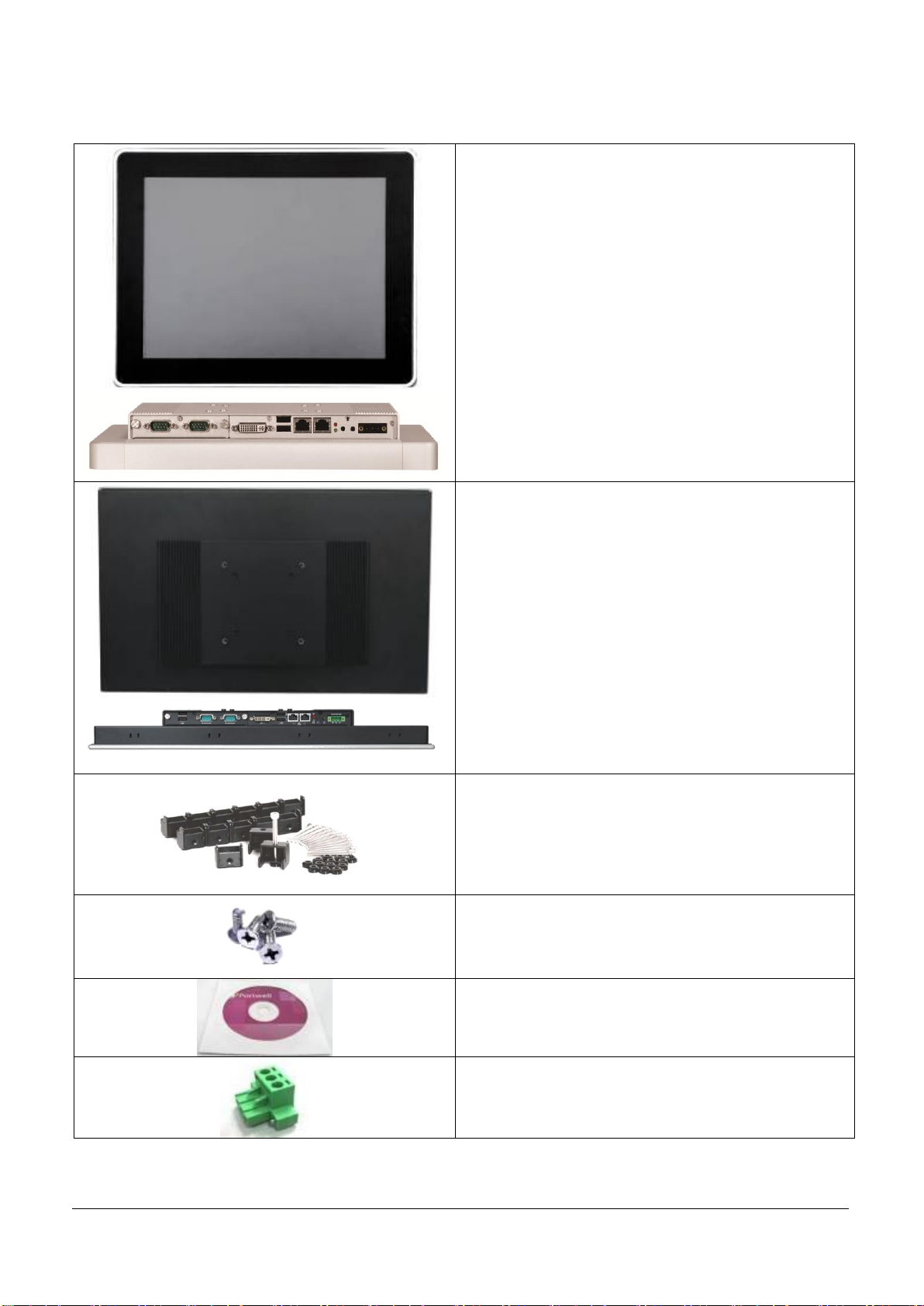
Panel PC system
Panel 12”
EUDA2-S1220
Panel 15”
EUDA2-S1520
The label (product designation, P/N and serial number)
is located on the rear side of the device.
Panel 18.5”
EUDA2-S1821 (wide screen 16:9)
The label (product designation, P/N and serial number)
is located on the rear side of the device.
Panel Mount kit
Panel 18.5”
EUDA2-S1821
16pcs
M3X4L Screws for HDD and HDD tray
Panel 12”
EUDA2-S1220
4pcs
Panel 15”
EUDA2-S1520
4pcs
Panel 18.5”
EUDA2-S1821
4pcs
Driver CD
(drivers and user’s manual)
3-pin terminal block connector
(female)
4. Scope of Delivery
EUDA2 Series 12”/15”/18.5” Panel PC User’s Manual (ver2.1) 8
Page 10
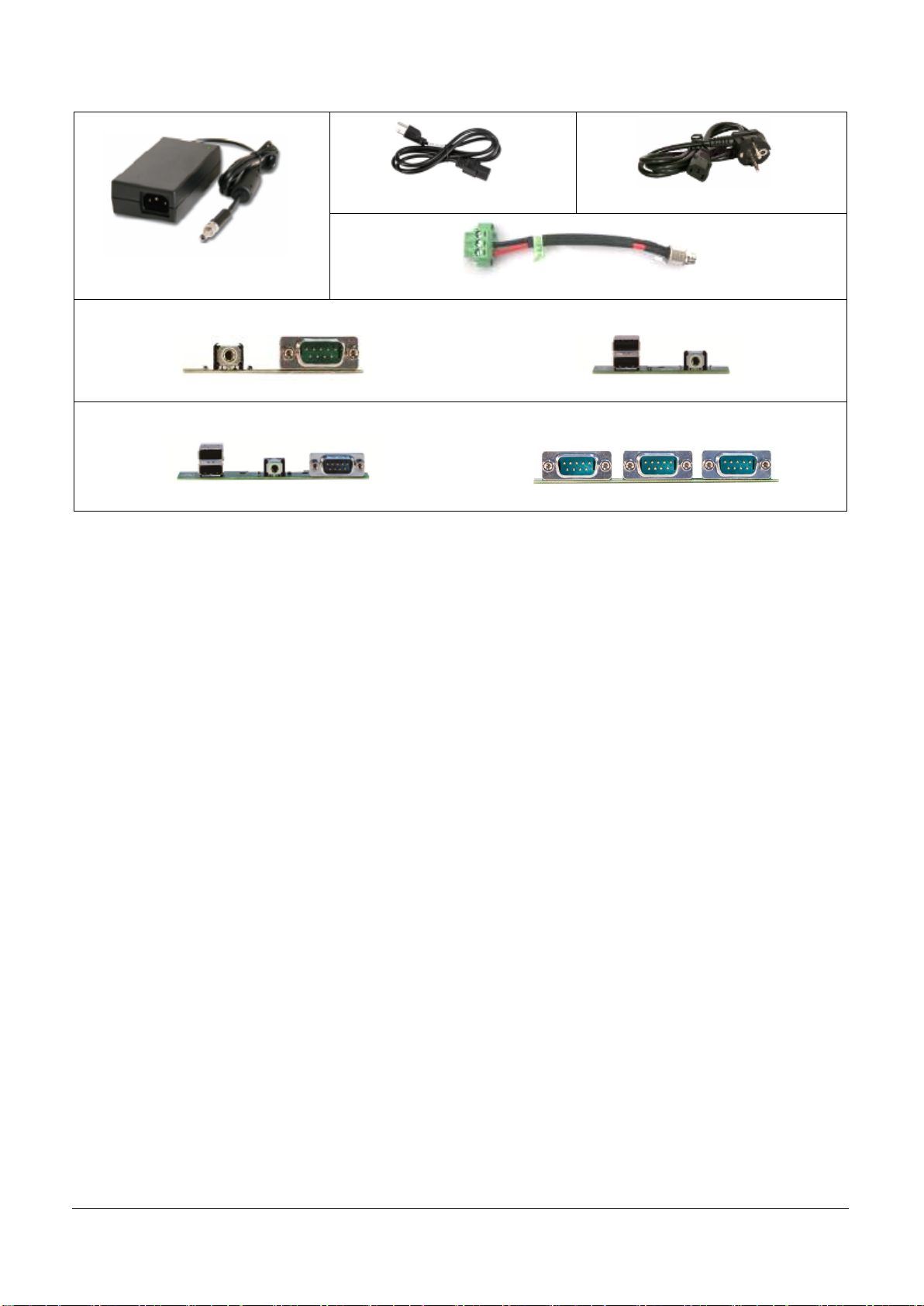
Optional accessories
AC/DC adapter (12V/60W)
Power cord (US)
Power cord (EU)
Power adaptor to 3 pin terminal block cable
Selectable I/O combination for EUDA2-S1220
1x RS-232/422/485 and 1x Line-out
2x USB ports and 1x Line-out
Selectable I/O combination for EUDA2-S1520 & EUDA2-S1821
1x RS-232/422/485, 2x USB ports and 1x Line-out
2x RS-232/422/485, 1x RS-232
EUDA2 Series 12”/15”/18.5” Panel PC User’s Manual (ver2.1) 9
Page 11
Product Description
5. Product Description
The EUDA2 Panel PC Series system, EUDA2-S1220/EUDA2-S1520/EUDA2-S1821, is a Human Machine Interface
(HMI) system with integrated a projected capacitive multi-touch screen designed for harsh industrial
applications.
The rugged design with a brilliant mechanical firmness demonstrates the superior qualities of a Panel PC
suitable for the operation in strict industrial environment.
Before you begin using your EUDA2 Panel PC Series ystem, you should take a few minutes to learn about the
various ports, bays, connectors and indicators that are part of your EUDA2 Panel PC Series system, as well as
the components that compose your system.
The EUDA2 Panel PC Series system, EUDA2-S1220/EUDA2-S1520/EUDA2-S1821, has many special features:
(1) Lower Power ATOM Cedar View 1.86GHz D2550 Processor and Fan-free System.
(2) In front of the projected capacitive multi-touch panel, a true flat window with anti-reflection is attached.
(3) The True flat window protects the display from dust, water and accidental contact.
(4) Three-pin terminal block connector for power inlet from the adaptor to the unit. Three-pin is the power
supplied from a wide input range DC +12V~+24V (± 20% tolerance) ;
(5) The I/O is a flexible design, main combination with 1x DVI-I port, 2x USB ports, 2x Gigabit Ethernet ports. In
addition, users may select expandable I/O combination for different application demands:
for EUDA2-S1220: 2 x RS-232/422/485 ports (Default) or 1 x Line-out, 1 x RS-232/422/485 (Optional) or 1 x
Line-out, 2 x USB ports (Optional)
for EUDA2-S1520 & EUDA2-S1821: 2 x USB ports, 2 x RS-232/422/485 (Default) or 1 x RS-232/422/485, 1 x
Line-out, 2 x USB ports (Optional) or 2 x RS-232/422/485, 1x RS-232 (Optional)
(6) Indicators of 1x HDD LED (rear side) and 1x Power LED (rear side) are designed.
(7) “Power On after AC Power Loss” when the power is supplied again, it will start Auto Power On (default
setting in BIOS).
(8) HDD and CF card are easily accessible for installation and maintenance.
(9) Brightness of Panel PC is adjustable by users through application software (API) of the OS system.
(10) The selectable RS-232/422/485 function can be set through BIOS.
When powering on EUDA2 Panel PC Series system, EUDA2-S1220/EUDA2-S1520/EUDA2-S1821,
please make sure that the air intake and exhaust openings are not blocked.
Features of ease-of-use, slim-type, fan-free, noise-less and low power consumption should be emphasized as
well.
EUDA2 Series 12”/15”/18.5” Panel PC User’s Manual (ver2.1) 10
Page 12
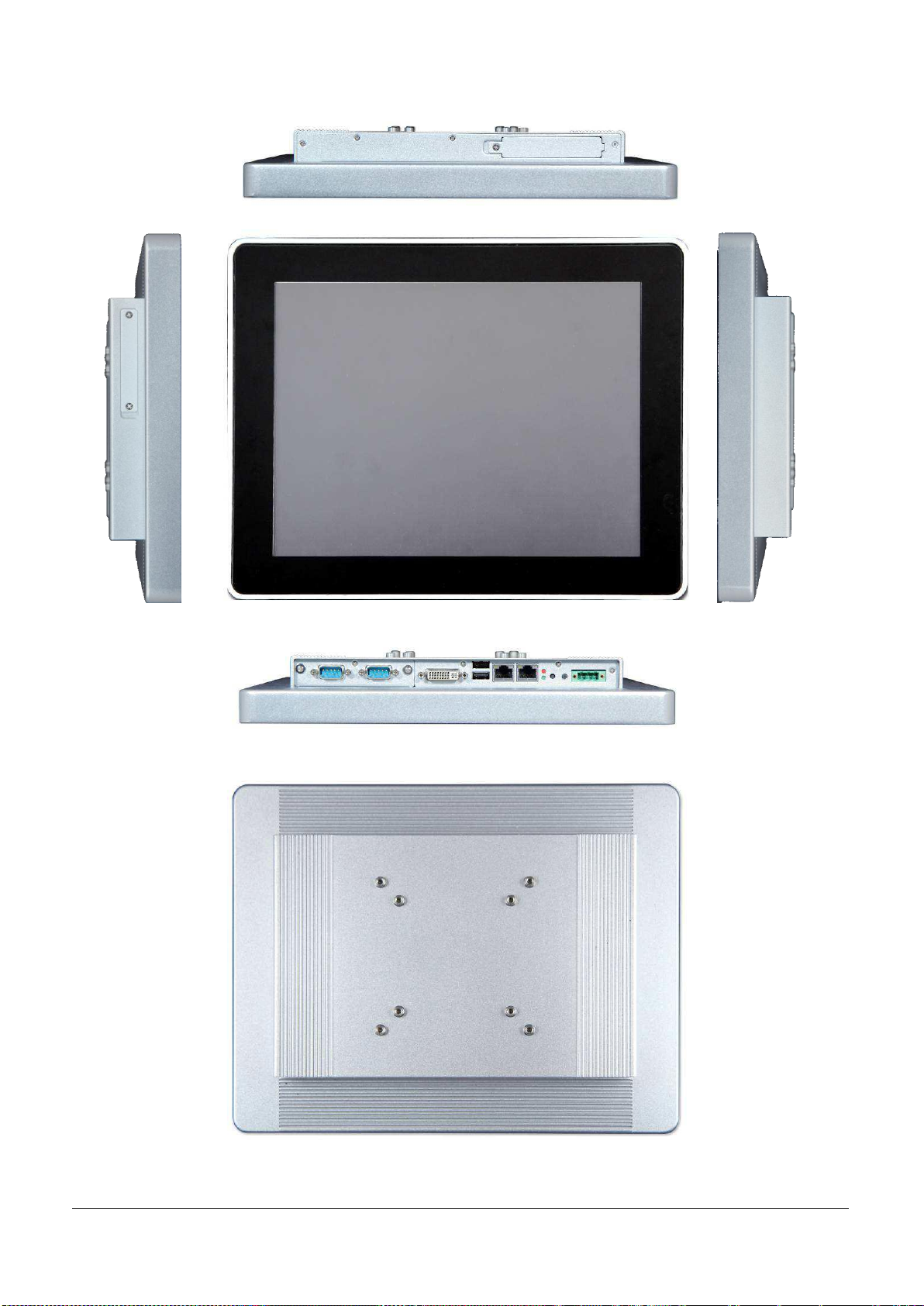
Outlook of the Operator Interface Computer EUDA2 Panel PC Series system is below.
Fig 5-1: Top view of the EUDA2-S1220 Panel PC System (12”)
Fig 5-2:
Right view
Fig 5-3:Front view of the EUDA2-S1220 Panel PC System (12”)
Fig 5-4:
Left view
Fig 5-5: Bottom view of the EUDA2-S1220 Panel PC System (12”)
Fig 5-6: Rear view of the EUDA2-S1220 Panel PC System (12”)
EUDA2 Series 12”/15”/18.5” Panel PC User’s Manual (ver2.1) 11
Page 13
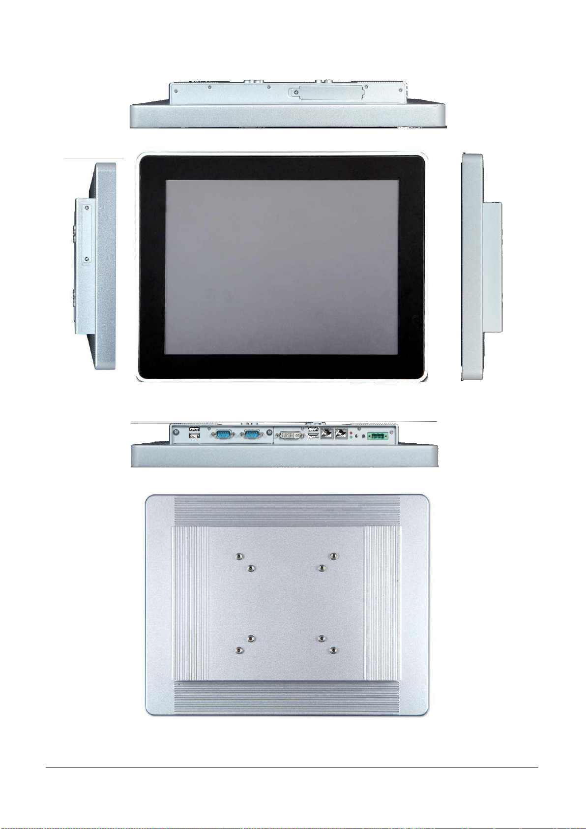
Fig 5-7:Top view of the EUDA2-S1520 Panel PC System (15”)
Fig 5-8:
Right view
Fig 5-9: Front view of the EUDA2-S1520 Panel PC System (15”)
Fig 5-10:
Left view
Fig 5-11:Bottom view of the EUDA2-S1520 Panel PC System (15”)
Fig 5-12: Rear view of the EUDA2-S1520 Panel PC System (15”)
EUDA2 Series 12”/15”/18.5” Panel PC User’s Manual (ver2.1) 12
Page 14
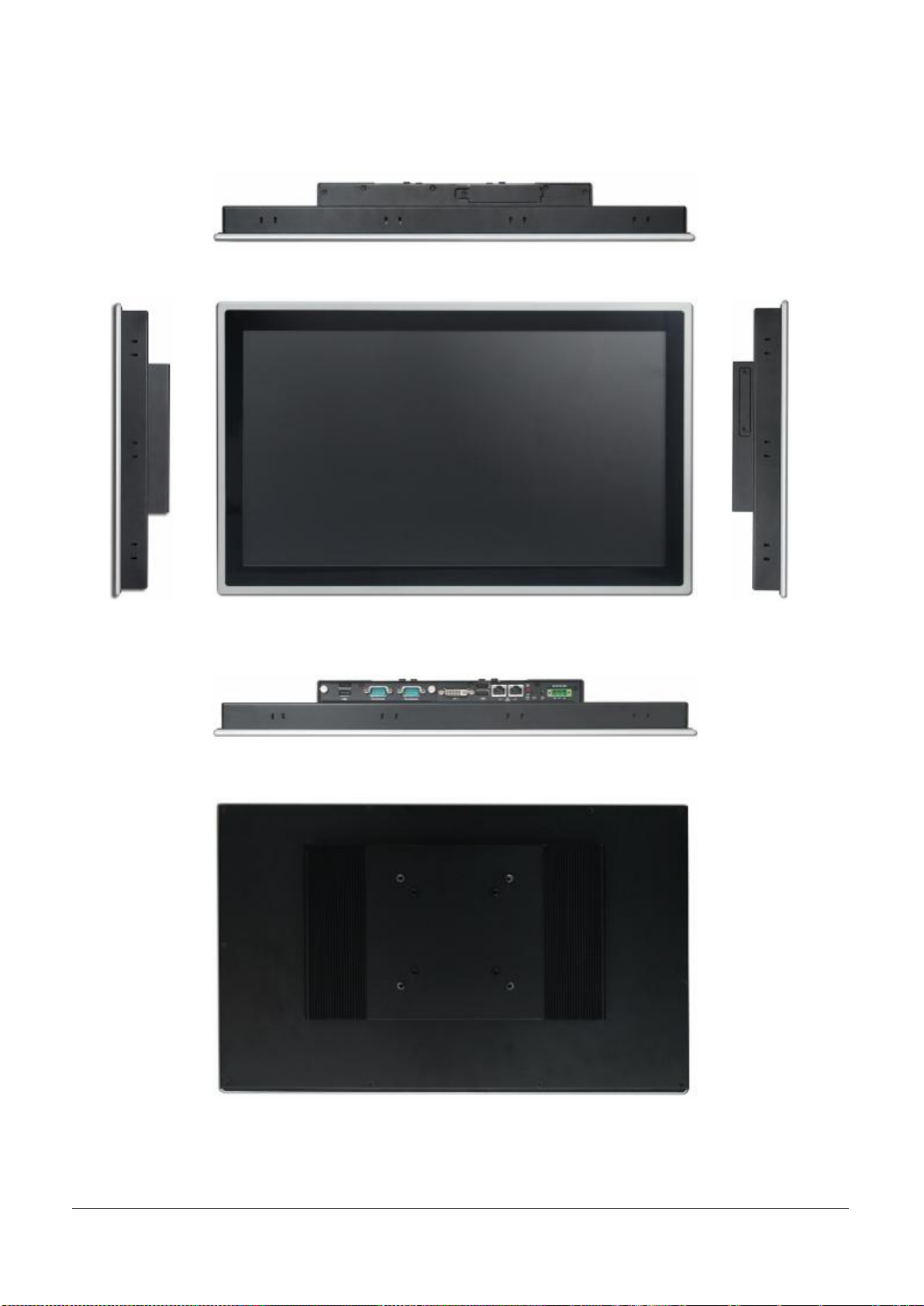
Fig 5-13:Top view of the EUDA2-S1821
Fig 5-14:
Right view
Fig 5-15: Front view of the EUDA2-S1821
Fig 5-16:
Left view
Fig 5-17:Bottom view of the EUDA2-S1821
Fig 5-18: Rear view of the EUDA2-S1821
EUDA2 Series 12”/15”/18.5” Panel PC User’s Manual (ver2.1) 13
Page 15
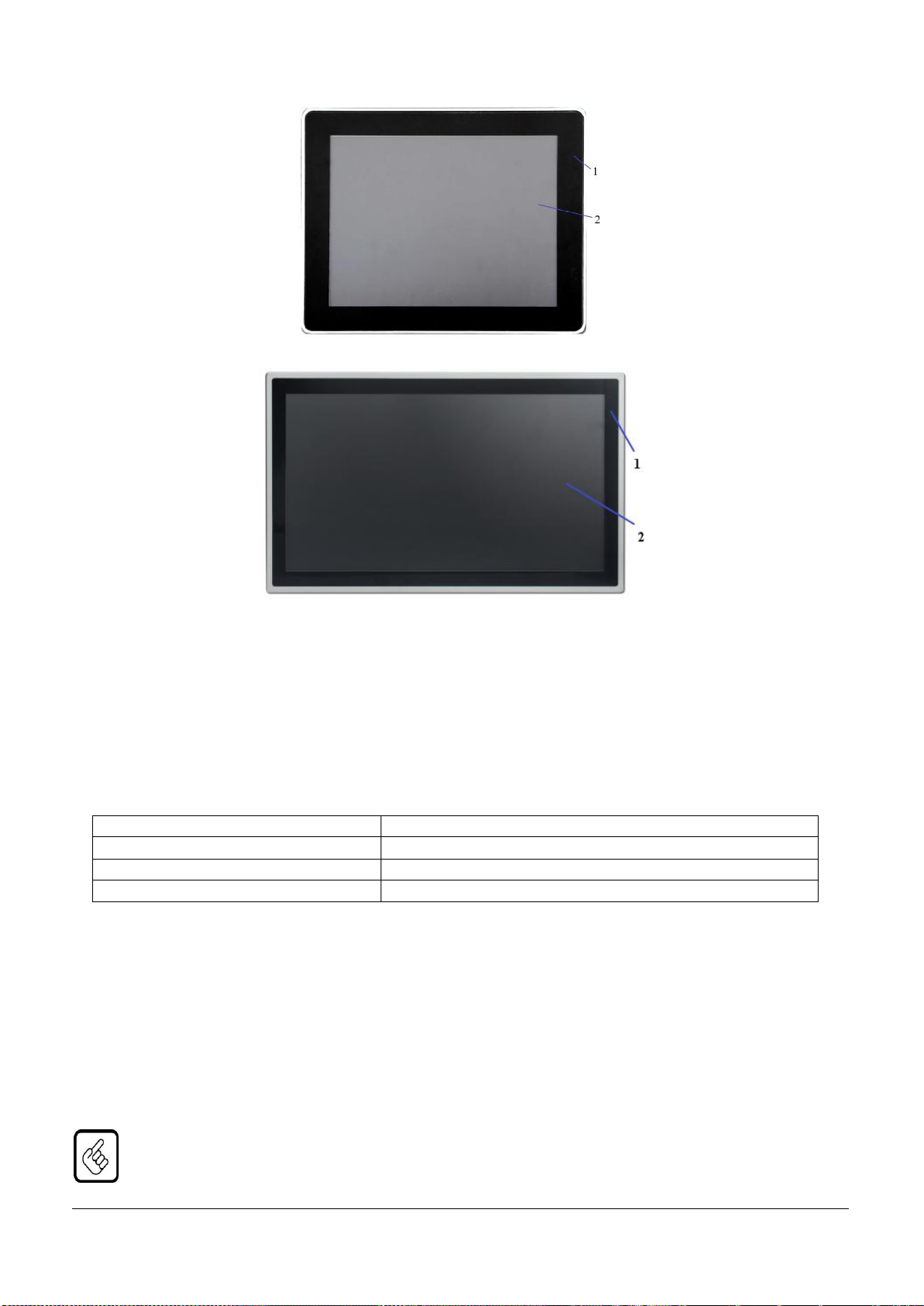
5.1 Front Side View
Fig 5-19: Front view of the EUDA2-S1520
Fig 5-20: Front view of the EUDA2-S1821
1
True Flat touch window for the 12”/15”/18.5”
display
2
12”/15”/18.5” TFT-LCD display with Projected
Capacitive Multi-Touch Screen
Dimension for[mm]
True Flat touch window dimension (W x H x D)
EUDA2-S1220
309.1 x 244.1 x 46.8 (mm)
EUDA2-S1520
355 x 279 x 48.8 (mm)
EUDA2-S1821
467.25 x 292.68 x 57.7 (mm)
All versions are suitable for installation in an instrument panel or other cabinet. On the front side are located:
◎ True Flat touch window for the 12”/15”/18.5” display
◎ 12”/15”/18.5” display with corresponding projected capacitive multi-touch screen
Depending on the size of the integrated display (12”/15”/18.5”), the outline dimensions of display unit are:
5.1.1 12”/15”/18.5” Display with Touch Screen
Depending on the ordered Operator Interface Computer EUDA2 Panel PC Series system, the built-in display is a
display of 12”/15”/18.5”. For technical specification of the built-in display, please refer to the section of
“Technical Data” in this manual.
The display is designed with a projected capacitive multi-touch. The surface of the display is also mechanically
protected through the touch screen. The touch screen (USB interface) registers contacts of a conductive object
such as a finger and allows moving the mouse pointer. It can sense a passive stylus or gloved fingers as well.
Users don’t need to install touch screen driver for projected capacitive multi-touch because driver is included in
operating system.
Do not use a hard or a pointed object (like screw drivers or pliers) to operate the touch screen, because
such an action will damage the surface of touch screen.
EUDA2 Series 12”/15”/18.5” Panel PC User’s Manual (ver2.1) 14
Page 16
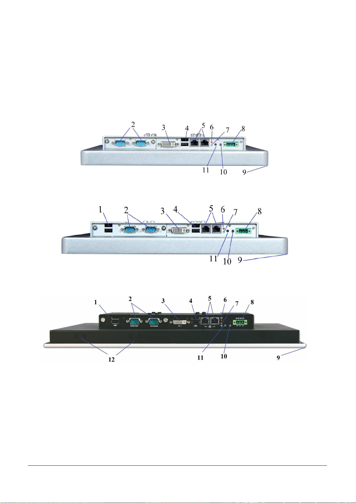
Fig 5-21: Bottom view of the EUDA2-S1220
Fig 5-22: Bottom view of the EUDA2-S1520
Fig 5-23: Bottom view of the EUDA2-S1821
1
2 x USB 1.1/2.0 (Expansion: Default)
7
1 x Power LED
2
2 x RS-232/422/485(Expansion: Default)
8
1 x 3-pin Terminal block connector
3
1 x DVI-I port
9
True Flat touch window
4
2 x USB 1.1/2.0 ports
10
1 x System Power Switch
5
11
1 x Reset Switch
6
1 x HDD LED
12
Panel Mount Holes
5.1.2 Front Panel Care and Cleaning
Mild detergent and water, or isopropyl alcohol is recommended for cleaning. Use of solvents with strong acidity
or alkalinity, which could react with the paint or printed color or plastic, should be avoided.
The True Flat touch screen surface is subject to burning and scaring from direct heat sources such as lighters or
cigarettes. The front display is against water and dust (IP54/IP65). The touch screen built in EUDA2 Panel PC
Series system can resist the following chemicals such as acetone, methylene chloride, methyl ethyl ketone,
isopropyl alcohol, hexane, unleaded gas, diesel fuel, motor oil vinegar, cooking oil, saline water, and so on.
5.2 Bottom View
EUDA2 Series 12”/15”/18.5” Panel PC User’s Manual (ver2.1) 15
Page 17
5.3. Power, Control Indicators, Reset and Grounding
Power Button (on the rear bottom side)
available
Power LED (on the rear bottom side)
available
The system is connected to
a DC power source
Power Button
(rear bottom)
Power LED
(rear bottom)
Status of Panel System,
EUDA2 Panel PC Series
12”/15”/18.5”
Panel PC System
Off
N/A
N/A
On
Green
The system is running or standby.
HDD Work
HDD LED
Off
N/A
On
Red
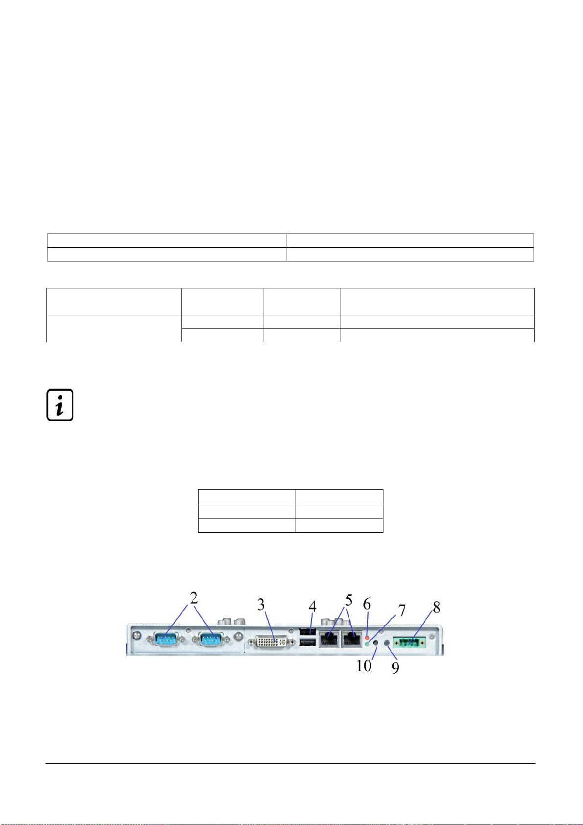
Fig 5-24: I/O view of the EUDA2-S1220
5.3.1 Power Connector
The DC Power connector (refer to Fig.5-21/22/23, pos.8) provides the power connection of the Operator
Interface Computer EUDA2 Panel PC Series system to the main power source via the DC power cable or the
AC/DC adapter.
Three-pin terminal block connector is for power inlet from the adaptor to the unit. Three-pin is the power
supplied from a wide input range DC +12V ~ +24V (± 20% tolerance).
5.3.1.1 Power Button and Power LED
The Operator Interface Computer EUDA2 Panel PC Series system, EUDA2-S1220/EUDA2-S1520/EUDA2-S1821,
power button on the rear side allows to Power ON/OFF EUDA2 Panel PC Series system, depending on the
settings for the power button in BIOS Setup (default setting is Power/After Power Failure/ON).
The power LEDs show the ON/OFF state of the system.
Table 1: Control indicators of the system
Table 2: System status
5.3.1.2 Reset Button
To restart the system, e.g. after a system hang-up, press the “RESET” button (Fig.5-21/22, pos.11).
The system restarts automatically; you don’t have to switch the computer off and on. During a reset
all data in the main memory will be erased.
5.3.1.3 HDD LED
The HDD LEDs show the ON/OFF state of the system. The EUDA2 Panel PC Series system is designed with a HDD
LED on the bottom (rear) side of the system (Fig.5-21/22, pos.6).
Table 3: HDD working status
5.3.2 Interfaces (Rear, Bottom Side of the System)
EUDA2 Series 12”/15”/18.5” Panel PC User’s Manual (ver2.1) 16
Page 18
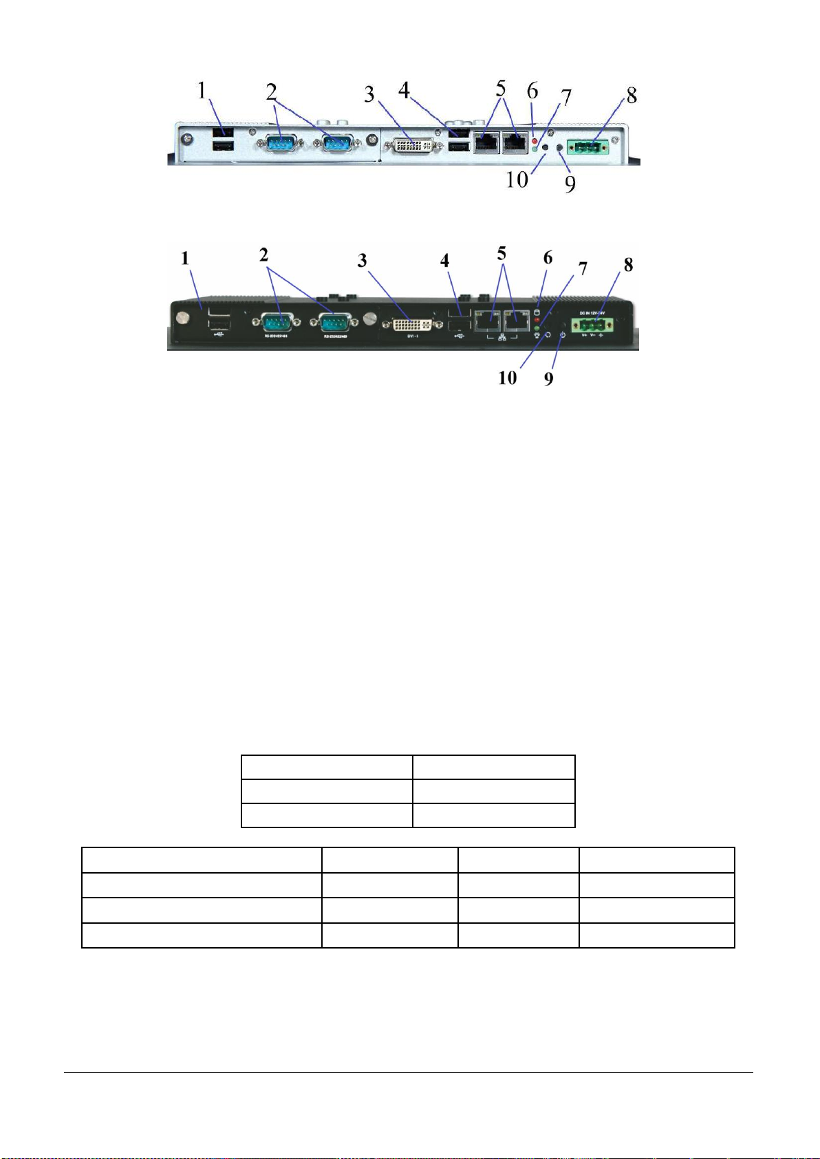
Fig 5-25: I/O view of the EUDA2-S1520
Fig 5-26: I/O view of the EUDA2-S1821
1
2 x USB 1.1/2.0 (Expansion;Default)
6
1 x HDD LED
2
2 x RS-232/422/485(Expansion;Default)
7
1 x Power LED
3
1 x DVI-I port
8
1 x 3-pin Terminal block connector
4
2 x USB 1.1/2.0 ports
9
1 x System Power Switch
5
10
1 x Reset Switch
Ethernet Port
Data Transfer Rate
LAN1
10/100/1000 Mbps
LAN2
10/100/1000 Mbps
Ethernet LED States: Left LED State
Link Activity State
Right LED State
Link Speed
Off
No Active
Off
10 Base-T
Yellow
Active
Green
100 Base-T
Orange
1000 Base-T
5.3.2.1 USB Connectors
The system is equipped at the bottom side (rear) with two USB 2.0 interface connectors and two USB 2.0
interfaces for additional extension (pos.1 and pos.4, Fig.5-24/25/26). These provide connections for USB
compatible devices.
5.3.2.2 COM port Serial Interface Connector
These two RS232/RS422/RS485 connectors (pos.2, Fig.5-24/25/26) are available for extensional selection.
5.3.2.3 LAN1 and LAN2 Ethernet Interface Connectors
These interface connectors (pos. 5, Fig.5-24/25/26) are provided as RJ45 sockets with integrated LEDs.
5.3.2.4 DVI-I Interface Connector
An external monitor can be plugged into this interface (pos.3, Fig. 5-24/25/26) which is provided as a DVI-I.
EUDA2 Series 12”/15”/18.5” Panel PC User’s Manual (ver2.1) 17
Page 19
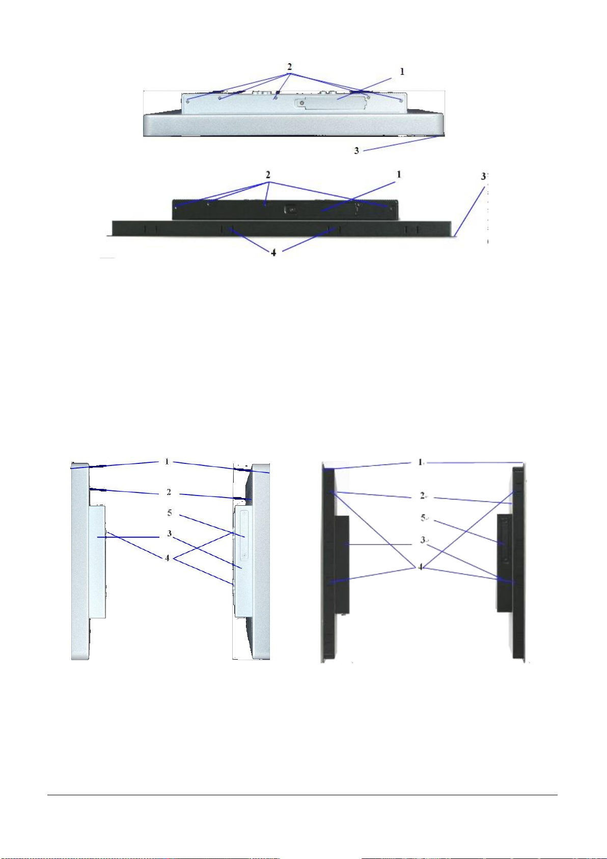
5.4 Top View
Fig 5-27:Top view of the EUDA2-S1220/EUDA2-S1520
Fig 5-28:Top view of the EUDA2-S1821
1
HDD Bracket & HDD Tray
2
Screws that secure the cover on the top side
3
Front panel with seal on the rear side
4
Panel Mounting Slots with installed mounting clamp and screw
Fig.5-29: Right/Left side of the
EUDA2-S1220/EUDA2-S1520
Fig.5-30: Right Left side of the EUDA2-S1821
1
Front panel of the system with seal at the
rear side
4
VESA/Panel* Mounting slots with installed
mounting clamp and Allen Screw
*only EUDA2-S1821 supports Panel Mount)
2
Enclosure of the display
3
IPC back cover
5
Cover the obstructs the access to the CF-slot
The Operator Interface Computer EUDA2 Panel PC Series system, EUDA2-S1220/EUDA2-S1520/EUDA2-S1821,
is configured with an internal 2.5" SATA HDD inside an easily removable bracket and also configurable with a
cover (refer to pos. 1, Fig.5-27/28) in order to prevent it from intrusion access.
5.5 Left and Right Side View
EUDA2 Series 12”/15”/18.5” Panel PC User’s Manual (ver2.1) 18
Page 20
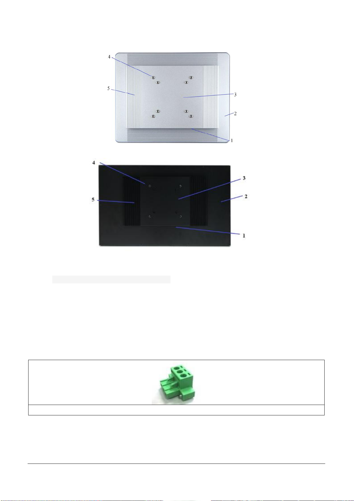
Fig 5-31: Rear view of the EUDA2-S1220/EUDA2-S1520
Fig 5-32: Rear view of the EUDA2-S1821
1
I/O interface at the rear side
4
IPC back Cover
2
Septum assembly module
5
Fins on back cover
3
VESA® 75/100 compliant
Fig.5-31: 3 pin terminal block connector(female) supplied with EUDA2 Panel PC Series system
5.6 Rear View
5.7 Rear View
The EUDA2 Panel PC Series system, can be connected to a DC power source via a 3 pin terminal block
connector(female, included) and optionally to an AC power source via an AC/DC adapter (optional, not
included).
5.7.1 DC power connector
5.7.2 External AC/DC Adapter (Optional)
The external AC/DC power adapter is an optional part. If ordered, the AC/DC power adapter will be connected
to PC system with 3 pin terminal block cable.
EUDA2 Series 12”/15”/18.5” Panel PC User’s Manual (ver2.1) 19
Page 21
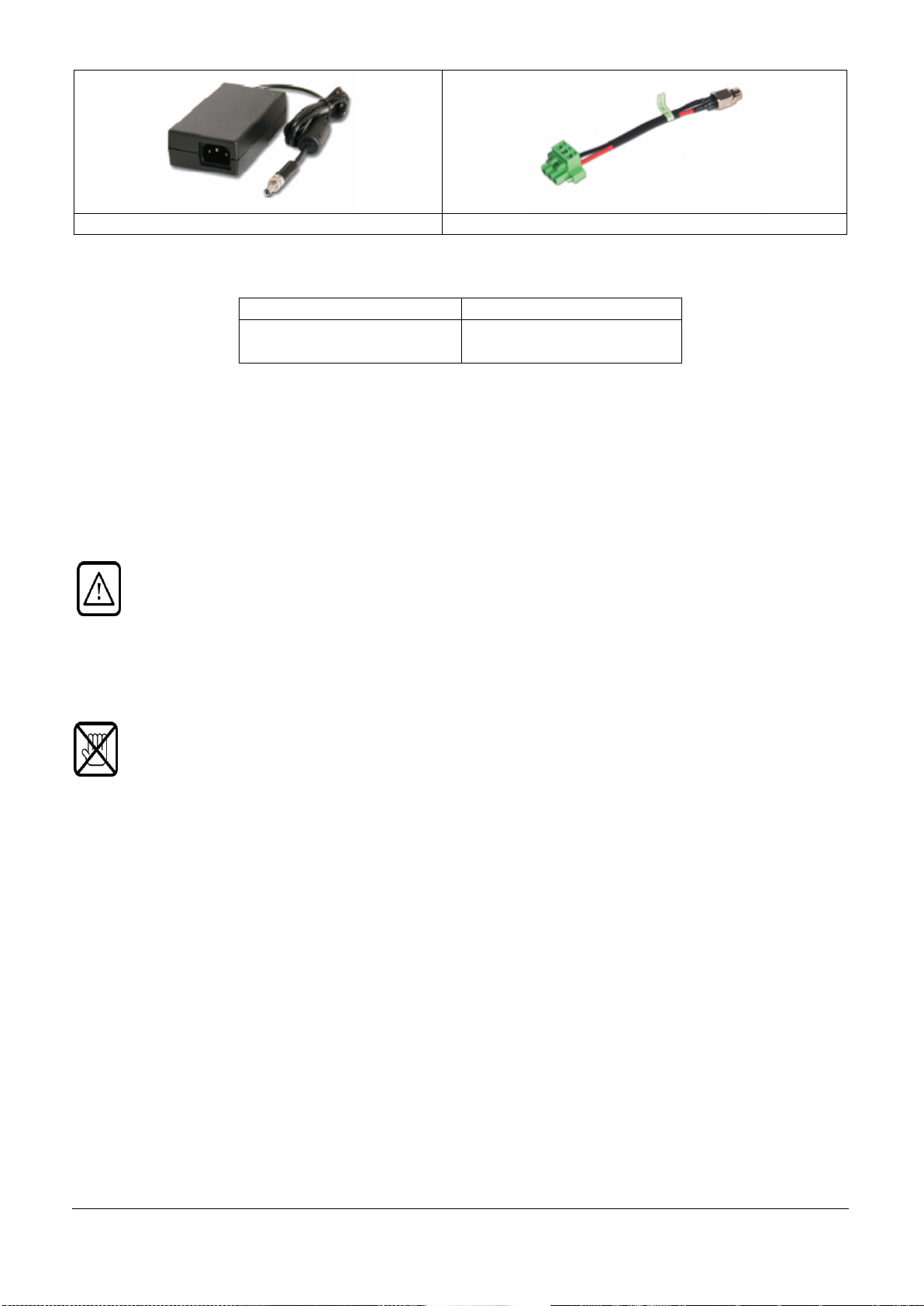
Fig.5-32:External AC/DC 12V/60W adapter
Fig.5-33:Power adaptor to 3 pin terminal block cable
AC Input
DC Output
90-264V
1.5A ;50-60Hz
12V DC
5A
Electrical Specifications for the AC/DC Adapter
For connecting to the system and power refer to “Connecting to Power”.
Cable Out: Non-Shielded, with one ferrite core bonded.
5.8. Accessing Internal Components
This section contains important information that you must read before accessing the internal components. You
must follow these procedures properly when handling any board components of the system.
Before removing the cover of the EUDA2 Panel PC Series system, EUDA2-S1220/EUDA2-S1520/
EUDA2-S1821, in order to gain access to the internal components, the system must be powered-down
and the power cord has to be disconnected from the power source.
The system may only be opened in accordance with the description in this user’s manual for: Configuration of
the RS232/ RS422 / RS485 interface. (Refer to COM port mode by BIOS setting)
These procedures have to be carried-out only by a qualified specialist.
It is not allowed to operate the system without installed cover.
Please observe the safety instruction for handling assemblies with static sensitive device. Failure to
take heed of this warning instruction can result in damage to the device.
EUDA2 Series 12”/15”/18.5” Panel PC User’s Manual (ver2.1) 20
Page 22
System Installation
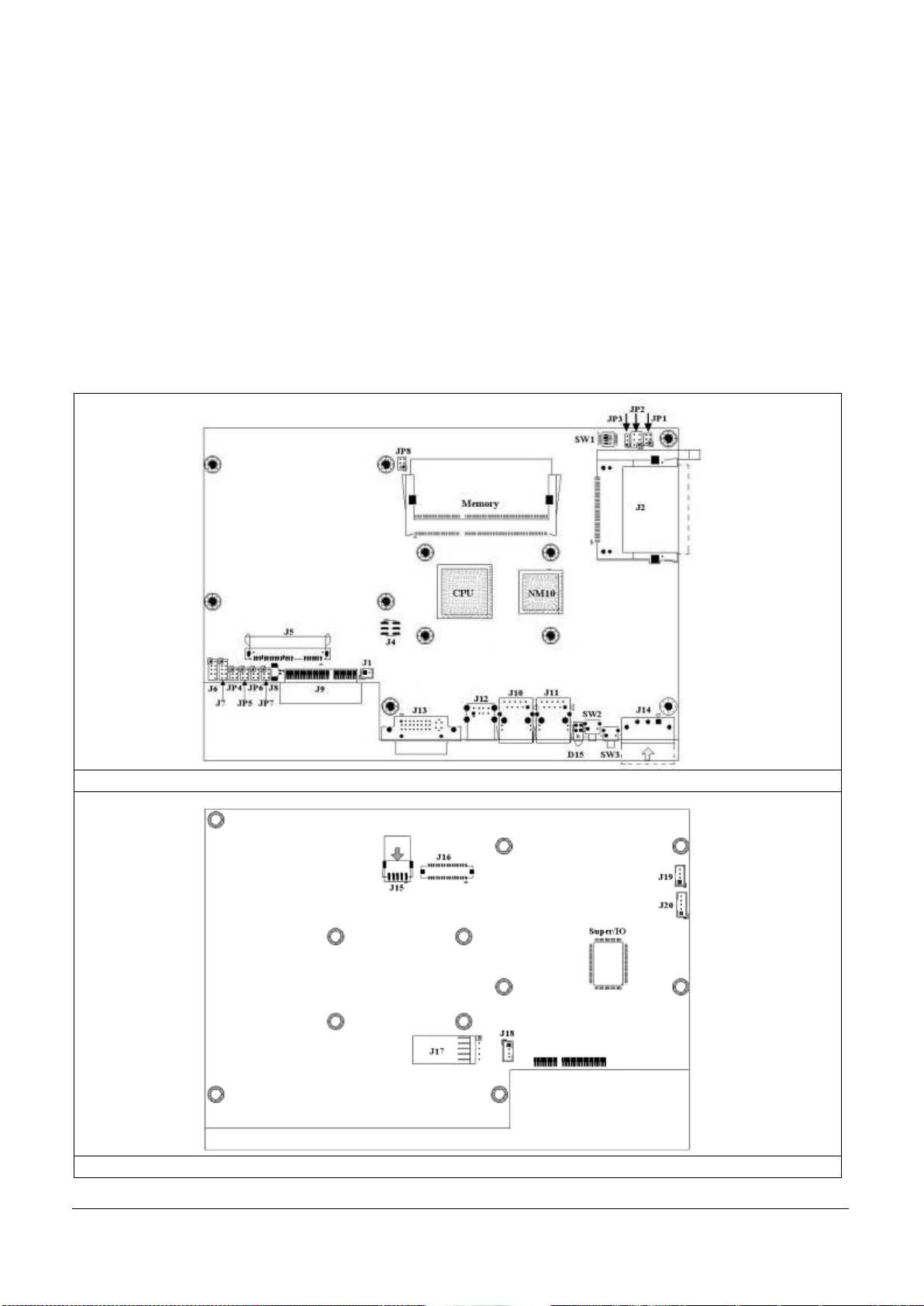
Figure 6-1: Top-side Jumper and Connector Locations (Component Side)
Figure 6-2: Top-side Jumper and Connector Locations (Solder Side)
6. System Installation
For Technical Support for Portwell Panel-PC hardware, contact your local Portwell Distributors or
Portwell’s Technical Support. For more information, please refer to the “Technical Support” section in
this manual.
6.1 H/W Installation
6.1.1 Connector & Jumping Setting
You may configure the EUDA2 Panel PC Series system, EUDA2-S1220/EUDA2-S1520/EUDA2-S1821, to match
the needs of your application by setting Jumpers on main board. To select any option, cover the jumper cap
(SHORT) or remove (NC) it from the jumper pins according to the following instructions. Here NC stands for
“Not Connect”.
EUDA2 Series 12”/15”/18.5” Panel PC User’s Manual (ver2.1) 21
Page 23
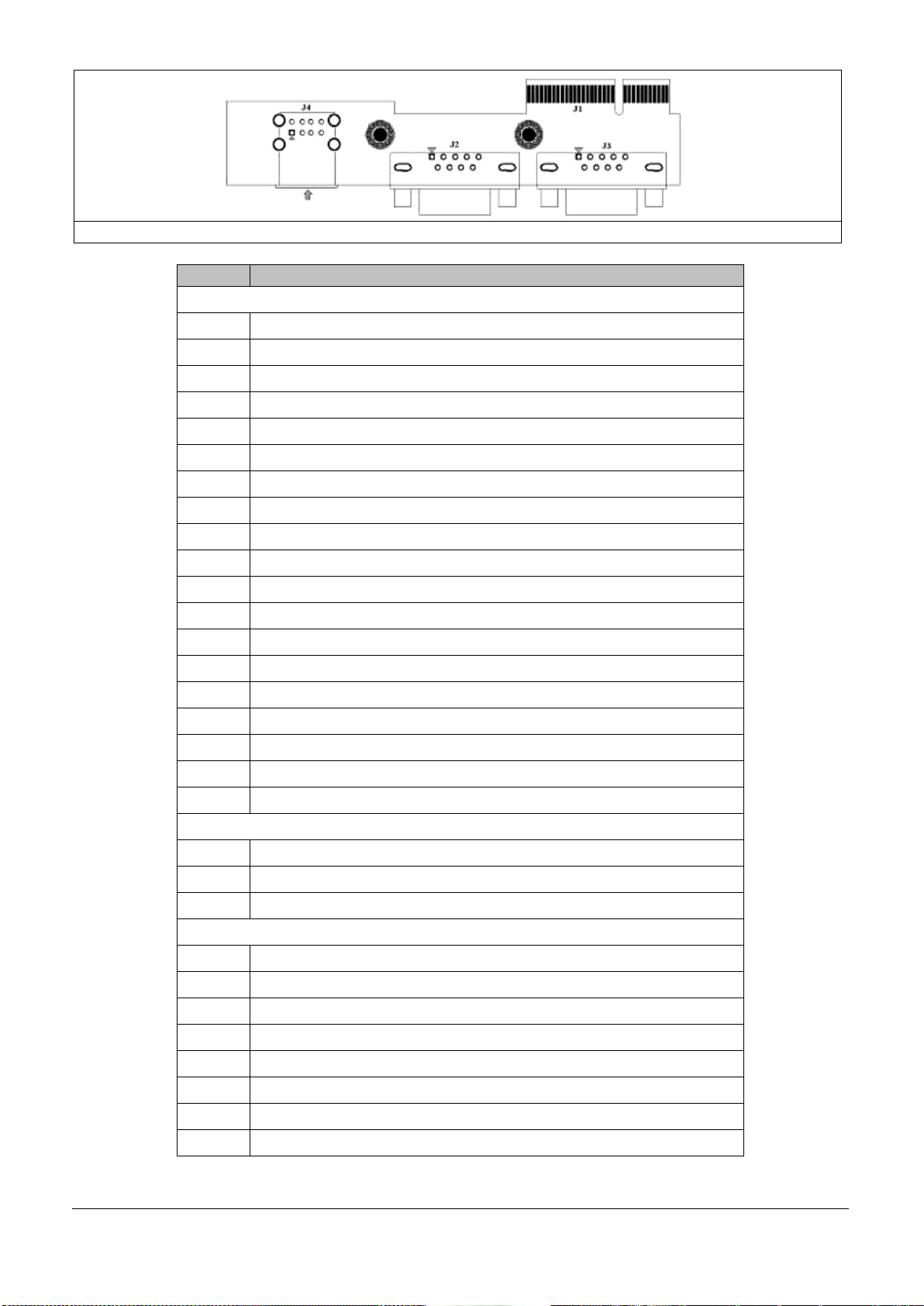
Figure 6-3: Top-side Jumper and Connector Locations (Daughter board) (default)
Item
Description
Connector(Main board)
J1
Case Open Detect Connector (1*2 Pin wafer/2mm)
J2
Compact Flash Type II Connector
J4
LCD LVDS Back Light Adjust Connector (3*2 Pin /2.54mm)
J5
SATA Port 0 Connector (Single Right Angel)
J6
LPC Debug Card Connector (2*5Pin cut Pin 9 Header /2mm)
J7
GPIO Connector (2*5 Pin Header/2mm)
J8
Battery Connector
J9
Golden Finger Connector
J10
LAN1 RJ-45 Connector
J11
LAN2 RJ-45 Connector
J12
USB Port 0~1 Connector (Type A)
J13
DVI-I Connector (DVI 29 Pin Male)
J14
Power Input Connector (Terminal Blocks 3Px1/5.08mm female)
J15
LCD Inverter Power Connector (1*5 Pin wafer/2mm)
J16
LCD LVDS Connector (2*15 Pin Hirose/1.25mm)
J17
Touch Panel Connector (1*5 Pin Header/2.54mm)
J18
USB Port 4 Connector (1*4 Pin Wafer/2mm)
J19
USB Port 5 Connector (1*4 Pin Wafer/2mm)
J20
Front Panel Connector (1*5 Pin Wafer/2mm)
Connector(Daughter board) (default)
J1
Multi-function Connector
J2
COM1 Pin 9 Function Setup (from main board JP4 Setting)
J3
COM2 Pin 9 Function Setup (from main board JP5 Setting)
Jumper Setting
JP1
LCD Panel Inverter ON/OFF Signal Setup
JP2
LCD Panel Voltage Setup
JP3
CMOS Setup
JP4
COM1 Pin 9 Function Setup
JP5
COM2 Pin 9 Function Setup
JP6
COM4 Pin 9 Function Setup
JP7
COM3 Pin 9 Function Setup
JP8
LCD Panel Type Setup
EUDA2 Series 12”/15”/18.5” Panel PC User’s Manual (ver2.1) 22
Page 24
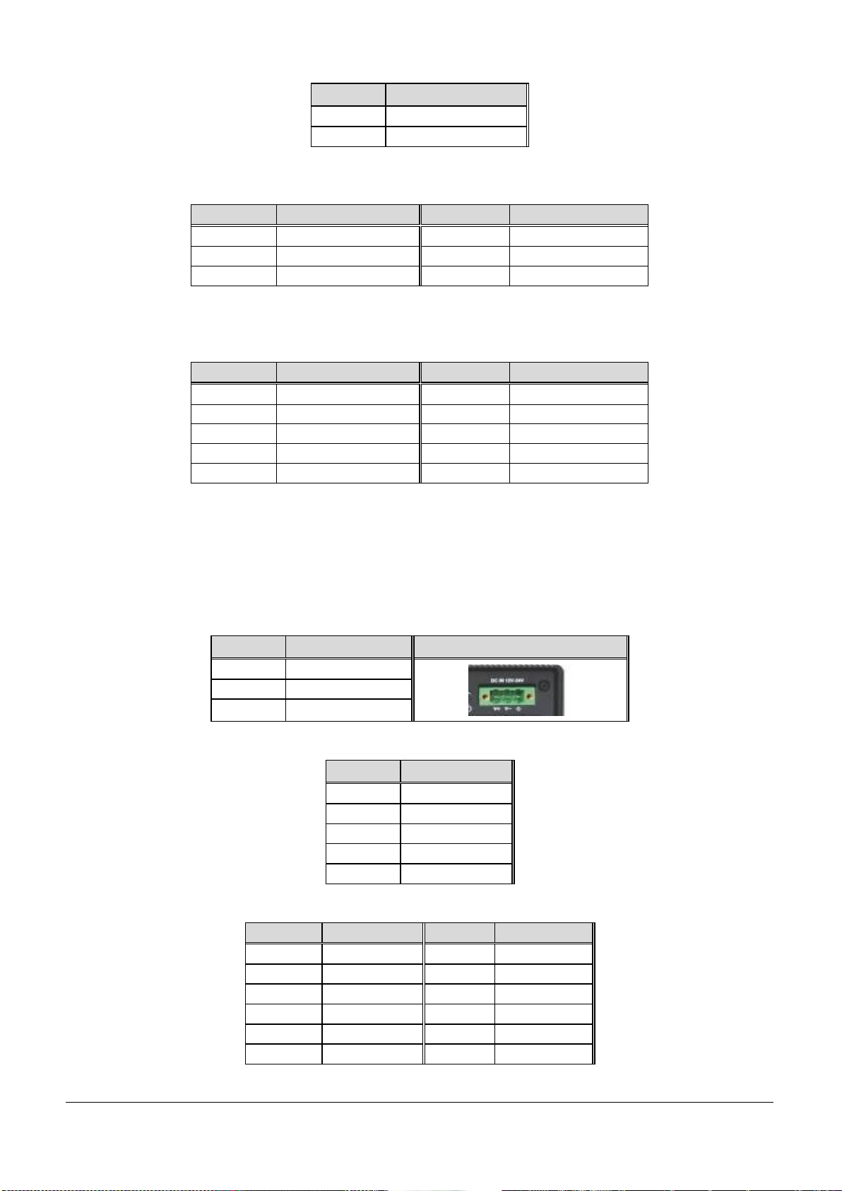
J1: Case Open Detect Connector (1*2 Pin wafer/2mm)
PIN NO.
DESCRIPTION
1
Case Open sensor
2
GND
PIN NO.
DESCRIPTION
PIN NO.
DESCRIPTION
1
GND
2
UP 3 GND
4
PWM Inverse
5
GND
6
DOWN
PIN NO.
DESCRIPTION
PIN NO.
DESCRIPTION
1
GPIO Port1
2
GPIO Port5
3
GPIO Port2
4
GPIO Port6
5
GPIO Port3
6
GPIO Port7
7
GPIO Port4
8
GPIO Port8
9
GND
10
+5V
PIN NO.
DESCRIPTION
Remark
1
GND EARTH
2
Vin-
3
Vin+
PIN NO.
Description
1
LCD_ENBLT
2
GND
3
+12V
4
LCD_BLADJ
5
+5V
PIN NO.
Description
PIN NO.
Description
1
YAP0
2
YAM0
3
YAP1
4
YAM1
5
YAP2
6
YAM2
7
YAP3
8
YAM3
9
CLKAP
10
CLKAM
11
YBP0
12
YBM0
J2: Compact Flash Type II Connector
J4: LCD LVDS Back Light Adjust Connector (3*2 Pin /2.54mm)
J5: SATA Port 0 Connector (Single Right Angel)
J6: LPC Debug Card Connector (2*5 Pin cut Pin 9 Header /2mm)
J7: GPIO Connector (2*5 Pin Header/2mm)
J8: Battery Connector
J9: Golden finger Connector
J10: LAN1 RJ-45 Connector
J11: LAN2 RJ-45 Connector
J12: USB Port 0~1 Connector (Type A)
J13: DVI-I Connector (DVI 29 Pin Male)
J14: Power Input Connector (Terminal Blocks 3Px1/5.08mm female)
J15: LCD Inverter Power Connector (1*5 Pin wafer/2mm)
J16: LCD LVDS Connector (2*15 Pin Hirose/1.25mm)
EUDA2 Series 12”/15”/18.5” Panel PC User’s Manual (ver2.1) 23
Page 25
13
YBP1
14
YBM1
15
YBP2
16
YBM2
17
YBP3
18
YBM3
19
CLKBP
20
CLKBM
21
DDCPCLK
22
DDCPDATA
23
GND
24
NC
25
GND
26
GND
27
+LVDS
28
+LVDS
29
NC
30
+LVDS
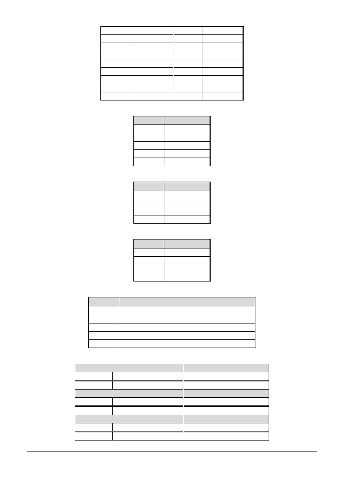
IN NO.
DESCRIPTION
1
UL 2 UR 3 Probe
4
LL 5 LR
PIN NO.
DESCRIPTION
1
+ 5V
2
USB_D-
3
USB_D+
4
GND
PIN NO.
DESCRIPTION
1
+ 5V
2
USB_D-
3
USB_D+
4
GND
PIN NO.
DESCRIPTION
1
LED (Hi: Green LED +; Low: Orange LED -)
2
LED (Hi: Orange LED+; Low: Green LED-)
3
PWR_ON_SW#
4
Ground
5
NC
PIN NO.
DESCRIPTION
1-3
2-4
Short
Short
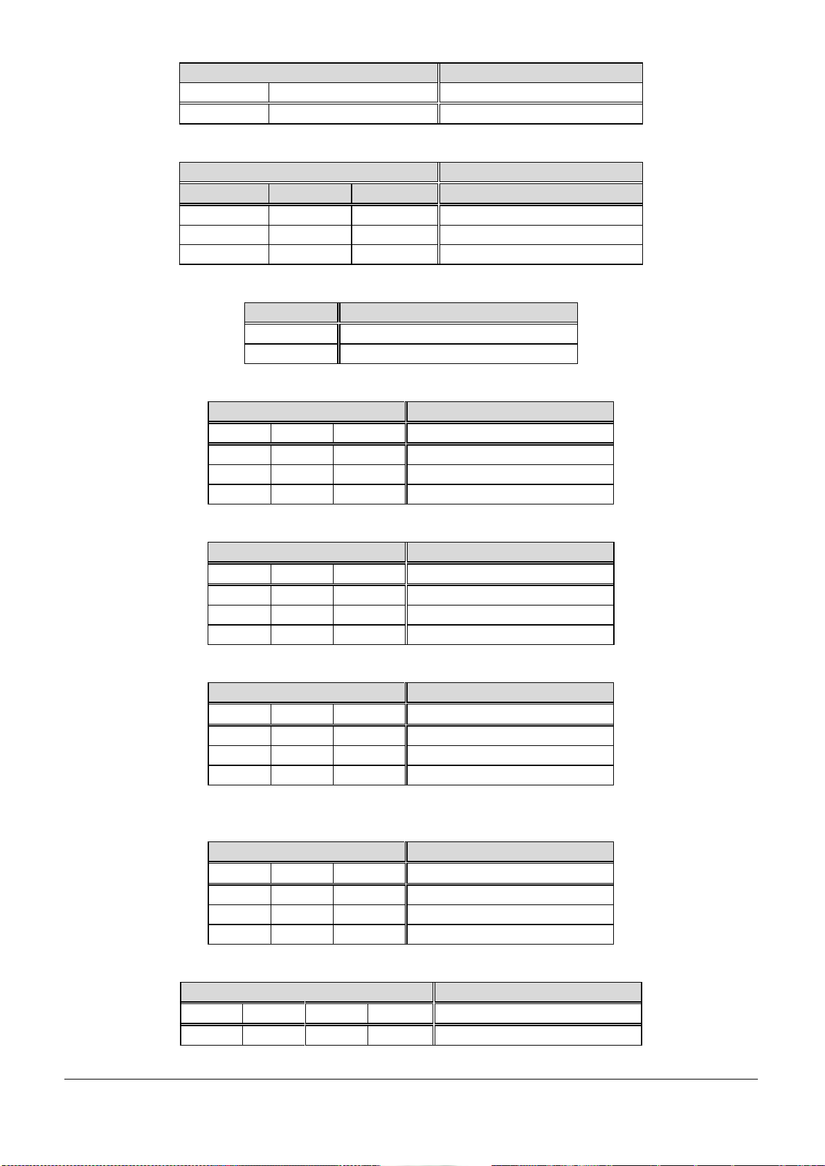
+5V High Active(Default)
PIN NO.
DESCRIPTION
1-3
4-6
Short
Short
+12V High Active
PIN NO.
DESCRIPTION
2-4
3-5
Short
Short
+5V Low Active
J17: Touch Panel Connector (1*5 Pin Header/2.54mm)
J18: USB Port 4 Connector (1*4 Pin Wafer/2mm)
J19: USB Port 4 Connector (1*4 Pin Wafer/2mm)
J20: Front Panel Connector (1*5 Pin Wafer/2mm)
JP1: LCD Panel Inverter ON/OFF Signal Setup
EUDA2 Series 12”/15”/18.5” Panel PC User’s Manual (ver2.1) 24
Page 26
PIN NO.
DESCRIPTION
3-5
4-6
Short
Short
+12V Low Active
PIN NO.
DESCRIPTION
1-3
3-5
3-4
Voltage
Short
+3.3V TFT LCD(Default)
Short
+5V TFT LCD
+12V TFT LCD
PIN NO.
DESCRIPTION
1-2
Normal (Keep CMOS Setup)
2-3
Clear CMOS Setup
PIN NO.
DESCRIPTION
1-2
3-4
5-6
Short
+5V Output
Short
RI Function(Default)
Short
+12V Output
PIN NO.
DESCRIPTION
1-2
3-4
5-6
Short
+5V Output
Short
RI Function(Default)
Short
+12V Output
PIN NO.
DESCRIPTION
1-2
3-4
5-6
Short
+5V Output
Short
RI Function(Default)
Short
+12V Output
PIN NO.
DESCRIPTION
1-2
3-4
5-6
Short
+5V Output
Short
RI Function(Default)
Short
+12V Output
PIN NO.
DESCRIPTION
1-3
3-5
2-4
4-6
Short
CCFL LCD
JP2: LCD Panel Voltage Setup
JP3: CMOS Setup
JP4: COM1 Pin 9 Function Setup
JP5: COM2 Pin 9 Function Setup
JP6: COM4 Pin 9 Function Setup
JP7: COM3 Pin 9 Function Setup
JP8: LCD Panel Type Setup
EUDA2 Series 12”/15”/18.5” Panel PC User’s Manual (ver2.1) 25
Page 27
Short
LED LCD
Short
CCFL LCD Brightness Limit
Short
LED LCD Brightness Limit
PIN NO.
Resolution
Port
1 2 3
4
ON
ON
ON
ON
800 x 600 (18bit)
Single
OFF
ON
ON
ON
1024 x768 (18bit)
Single
ON
OFF
ON
ON
1024 x768 (24bit)
Single
OFF
OFF
ON
ON
1280 x 768 (18bit)
Single
ON
ON
OFF
ON
1280 x 800 (18bit)
Single
OFF
ON
OFF
ON
1280 x 960 (18bit)
Single
ON
OFF
OFF
ON
1280 x 1024 (24bit)
Dual
OFF
OFF
OFF
ON
1366 x 768 (18bit)
Single
ON
ON
ON
OFF
1366 x 768 (24bit)
Single
OFF
ON
ON
OFF
1440 x 900 (24bit)
Dual
ON
OFF
ON
OFF
1400 x 1050 (24bit)
Dual
OFF
OFF
ON
OFF
1600 x 900 (24bit)
Dual
ON
ON
OFF
OFF
1680 x 1050 (24bit)
Dual
OFF
ON
OFF
OFF
1600 x 1200 (24bit)
Dual
ON
OFF
OFF
OFF
1920 x 1080 (24bit)
Dual
OFF
OFF
OFF
OFF
1920 x 1200 (24bit)
Dual
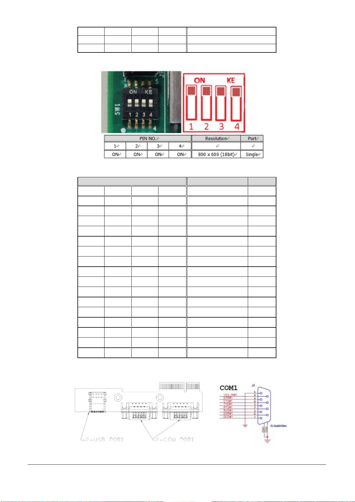
SW1: LCD Resolution Setup
Figure 6-4: Diagram of adjusting to resolution 800 x 600
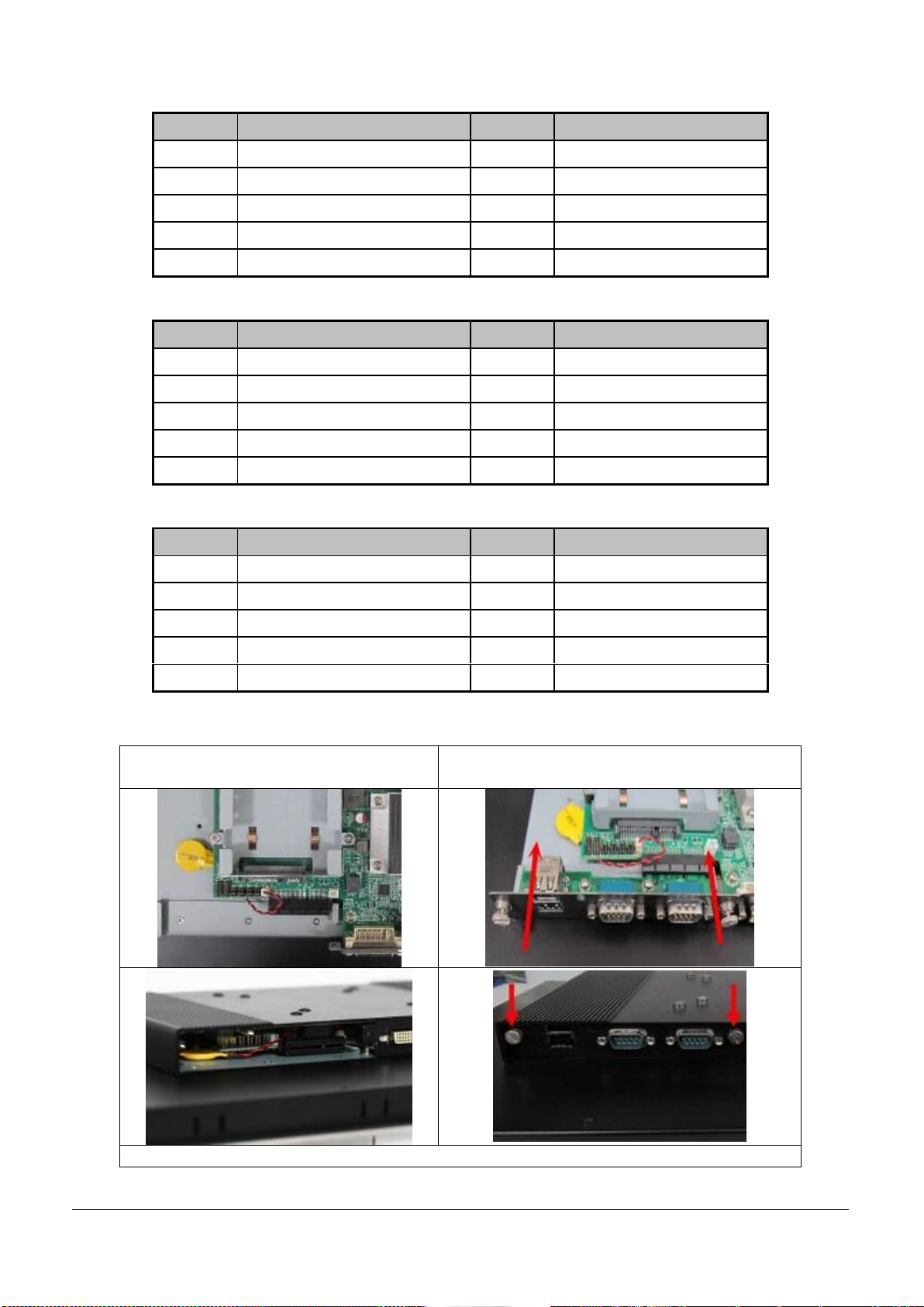
I/O board: PA-P1S2U2 (Default)
Figure 6-5: I/O board placement and COM port
EUDA2 Series 12”/15”/18.5” Panel PC User’s Manual (ver2.1) 26
Page 28
PIN No.
Signal Description
PIN No.
Signal Description
1
Data Carrier Detect (DCD)
2
Receive Data (RXD)
3
Transmit Data (TXD)
4
Data Terminal Ready (DTR)
5
GND
6
Data Set Ready (DSR)
7
Request to Send (RTS)
8
Clear to Send (CTS)
9
Ring Indicator (RI)
PIN No.
Signal Description
PIN No.
Signal Description
1
TX- 2 TX+ 3 Rx+ 4 Rx- 5 GND
6
RTS-
7
RTS+
8
CTS+
9
CTS-
PIN No.
Signal Description
PIN No.
Signal Description
1
DATA-
2
DATA+
3
NC
4
NC 5 GND
6
NC
7
NC 8 NC 9 NC
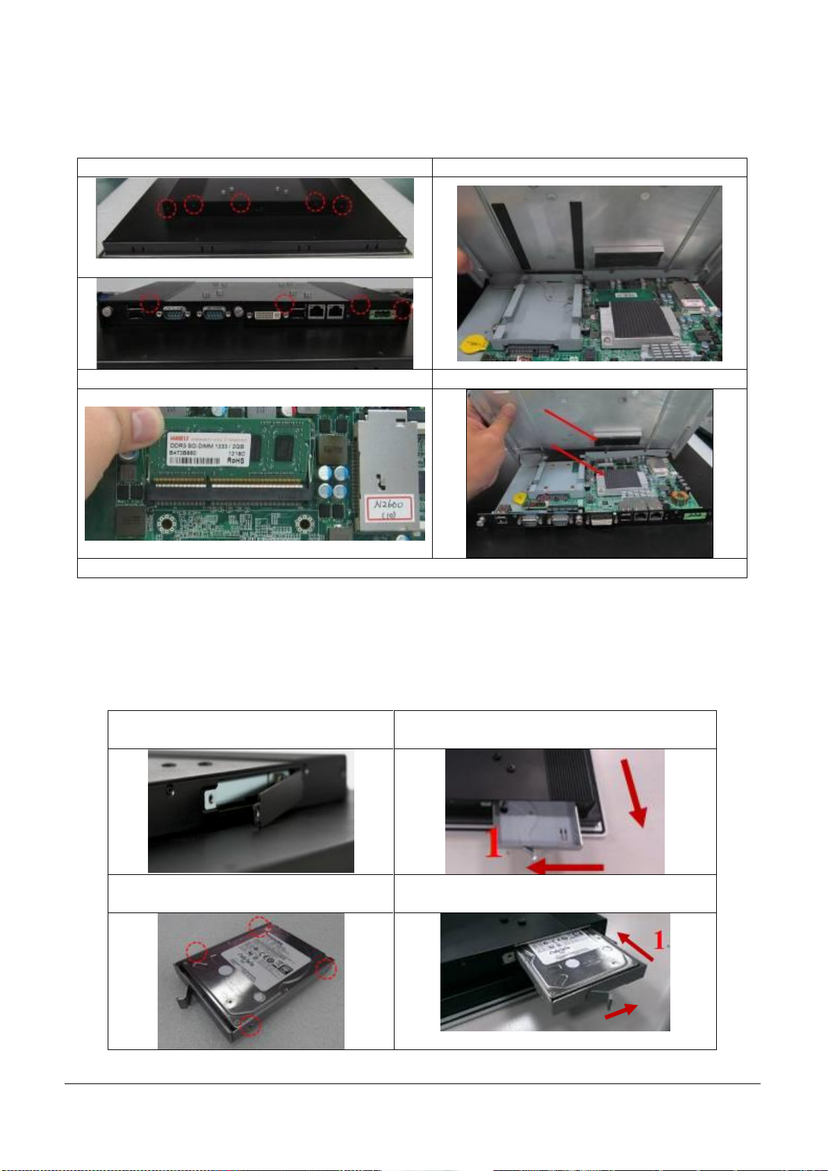
1. Confirm the position of Golden Finger
Connector
2. Fix the I/O daughter board to the main board
system
Figure 6-6: Installation of I/O daughter board
J2 RS-232 Mode Setup
J2 RS-422 Mode Setup
J2 RS-485 Mode Setup
6.1.2 Insert extended I/O daughter board
EUDA2 Series 12”/15”/18.5” Panel PC User’s Manual (ver2.1) 27
Page 29
6.1.3 Insert Memory module
1. Unscrew the IPC back cover to detach it
2. Remove the IPC back cover
Screw (M2.5x6L)
3. Insert Memory module to the slot.
4. Press down the Memory module and finish.
Figure 6-7: Installation of Memory
1. Remove the screw of HDD tray upper
cover on PPC
2. Push the rod to release HDD tray from PPC
3. Install the HDD into tray with screws
(※Must use M3X4L Screw 4pcs in Package)
4. Push HDD tray back into PPC system
2
2
The EUDA2 Panel PC Series system, EUDA2-S1220/EUDA2-S1520/EUDA2-S1821, is fully integrated at the
system assembly line before shipment. It’s not necessary for end users to do any assembly unless installing the
optional HDD, RAM, CF and/or Power Input. Installation of these optional components is described below.
6.1.4 Hard Disk Installation Method
Unlike IDE bus, each Serial Advanced Technology Attachment (SATA) channel can only connect to one SATA hard
disk at a time; the installation of SATA is simpler and easier than IDE, because the SATA hard disk doesn’t
require setting up Master and Slave, which can reduce mistake of hardware installation. The step 1-4 is HDD
installation, and step 4-1 is HDD un-installation. (※The HDD height must be less than 10mm).
EUDA2 Series 12”/15”/18.5” Panel PC User’s Manual (ver2.1) 28
Page 30
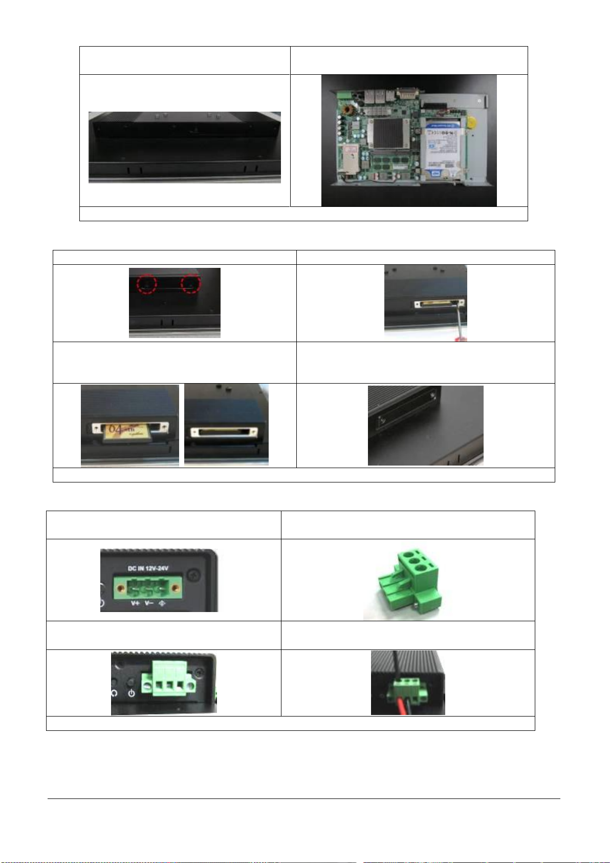
5. Finish installation and screw the upper
cover on PPC back in
6. Inside view of installed HDD on PPC system
Figure 6-8: Installation of HDD
1. Unscrew the side bracket of back cover
2. Remove the side bracket
3. Insert New CF card to CF socket carefully
(Ejection by pressing the elastic stick on the right
side, if necessary.)
4. Screw the side bracket and finish.
Fig. 6-9 : Side View of CF Card Insertion
1. Male-type 3-pin terminal block connector
2. Female type 3-pin terminal block connector(located
in the accessory kit.
3. Fix female type 3-pin terminal block connector
to the system by screw.
4. Fix power cable according to signal definition on
3-pin thermal block connector by screw.
Fig. 6-10 : Power adaptor installation
6.1.5 Insert CF Card
6.1.6 DC 12~24V Power Input Installation
EUDA2 Series 12”/15”/18.5” Panel PC User’s Manual (ver2.1) 29
Page 31
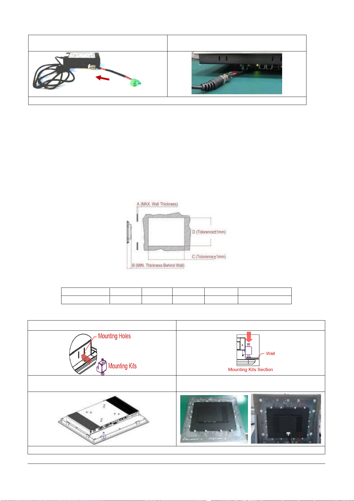
AC/DC Power adaptor installation (Optional)
1. Screw 3 pin terminal block cable to adaptor
2. Connect 3-pin terminal block connector to PPC
through AC in with adaptor
Fig.6-11: AC/DC 12V/60W adapter supplied with the EUDA2-S1821
(mm)
A B C D Mounting Kits
EUDA2-S1821
< 9
53.7
452
277
16
Insert panel mounting kit into panel mounting hole
Screw it to fix on steel wall
Screw the Clip tightly (Spec<=1.35 N )
Hook the mounting clamps with screws (included)
from the rear side of the panel
Fig. 6-13 : Mounting kit installation guide step by step
6.2 Panel & VESA Mounting
6.2.1 Panel Mounting (EUDA2-S1821 only)
The 18.5” EUDA2 Panel PC, EUDA2-S1821, configurations in the delivering status with mounted mounting
clamps (Fig. 6-12, depending on the ordered size). These mounting clamps have to be removed at first in order
to install the system into a sub-frame or a panel. Loosen the screws enough to allow the removing of the
mounting clamps from the enclosure (but do not entirely remove the screws from clamps).
First of all, check the wall thickness and the cut-out dimension, then insert the mounting kit step by step as the
following illustration.
Fig. 6-12: cut-out definition
Table 6-1: Cut-out Dimension by Panel size
EUDA2 Series 12”/15”/18.5” Panel PC User’s Manual (ver2.1) 30
Page 32
In order to ensure NEMA 4 front sealing against dust and water, mount the system on a non-textured
surface. Before you install 18.5” EUDA2 Panel PC, EUDA2-S1821, into a panel or a sub-frame for
industrial cabinet, verify the perfect condition of the seal at the rear of the front plate. The seal has to
be in place without injury/defects and dirt.
6.2.2 VESA® Mounting Plate
The EUDA2 Panel PC Series system, EUDA2-S1220/EUDA2-S1520/EUDA2-S1821, can be installed with
the provided (as optional part) VESA® 75/100 compliant adapter plate (refer to pos. 4, Fig.5-29/30).
Each VESA® 75/100 compliant mounting plate must be fasten to EUDA2 Panel PC Series system,
EUDA2-S1220/EUDA2-S1520/EUDA2-S1821, with four M4 x 4 metric screws (included).
Do not use longer screws than the original screws provided. Using longer screws may do harm to the internal
components of the system.
6.3 Getting started
The EUDA2 Panel PC Series system, EUDA2-S1220/EUDA2-S1520/EUDA2-S1821, is designed to be powered
from a DC power source via the included DC power cable. In order to use an AC power source as main power
source, order an AC/DC adapter (not included).
- Before using your system, you should first become familiar with the system components and confirm
everything is connected properly. Following a proper cabling procedure will prevent a false power-on
condition, which could result in unit operational failure.
-Also, it is recommended that the last cable attached to the system should be the power cable.
6.4 BIOS Setup
The EUDA2 Panel PC Series system, EUDA2-S1220/EUDA2-S1520/EUDA2-S1821, is equipped with the AMI BIOS
stored in Flash ROM. The BIOS has a built-in setup program that allows users to easily modify the basic system
configuration easily. This type of information is stored in CMOS RAM so that it is retained during power-off
periods. When system is turned on, the built-in main board communicates with peripheral devices and checks
its hardware resources against the configuration information stored in the CMOS memory. If any error is
detected, or the CMOS parameters need to be initially defined, the diagnostic program will prompt the user to
enter the SETUP program. Some errors are significant enough to abort the start up.
6.4.1 Entering Setup -- Launch System Setup
Power on the computer and the system will start POST (Power On Self Test) process. When the message below
appears on the screen, press the<Del> key to enter Setup.
Press <Delete> to enter SETUP
If the message disappears before you respond and you still wish to enter Setup, restart the system by turning it
OFF and On or pressing the RESET button. You may also restart the system by simultaneously pressing
<Ctrl>, <Alt>, and <Delete> keys.
Press <F1> to Run SETUP or Resume
The BIOS setup program provides a general help screen. You can call up this screen from any menu by simply
pressing <F1>. The Help screen lists the appropriate keys to use and the possible selections for the highlighted
item. Press <Esc> to exit the Help screen. (Fig 6-14)
6.4.2 Main
Use this menu for basic system configuration (Fig 6-14), such as time, date etc.
EUDA2 Series 12”/15”/18.5” Panel PC User’s Manual (ver2.1) 31
Page 33
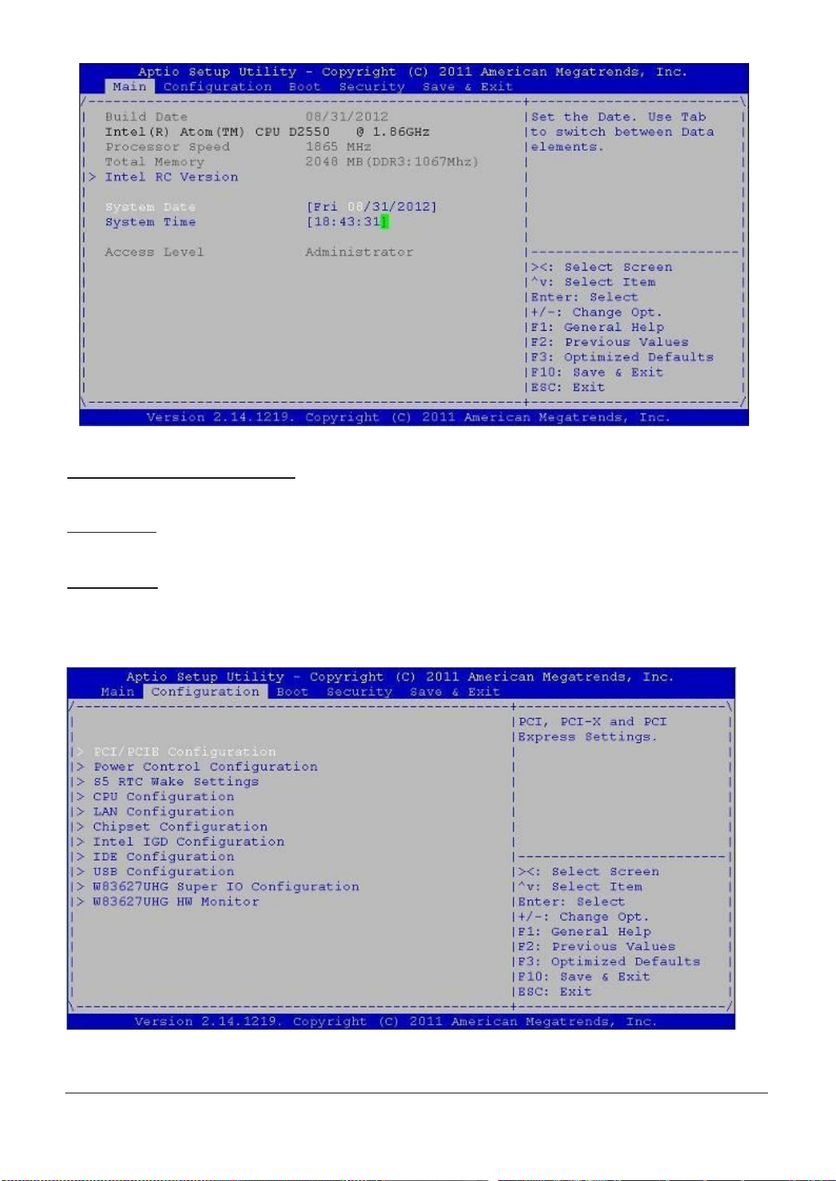
Fig. 6-14:Setup Program Initial Screen (Main)
Fig. 6-15:Setup Program configuration Screen
AMI BIOS, CPU, System Memory
These items show the firmware and hardware specifications of your system. Read only.
System Date
The date format is <Day>, <Month> <Date> <Year>. Use [+] or [-] to configure system Date.
System Time
The time format is <Hour> <Minute> <Second>. Use [+] or [-] to configure system Time.
6.4.3 Configuration
Use this menu to set up the items of special enhanced features.
EUDA2 Series 12”/15”/18.5” Panel PC User’s Manual (ver2.1) 32
Page 34
PCI/PCIE Configuration
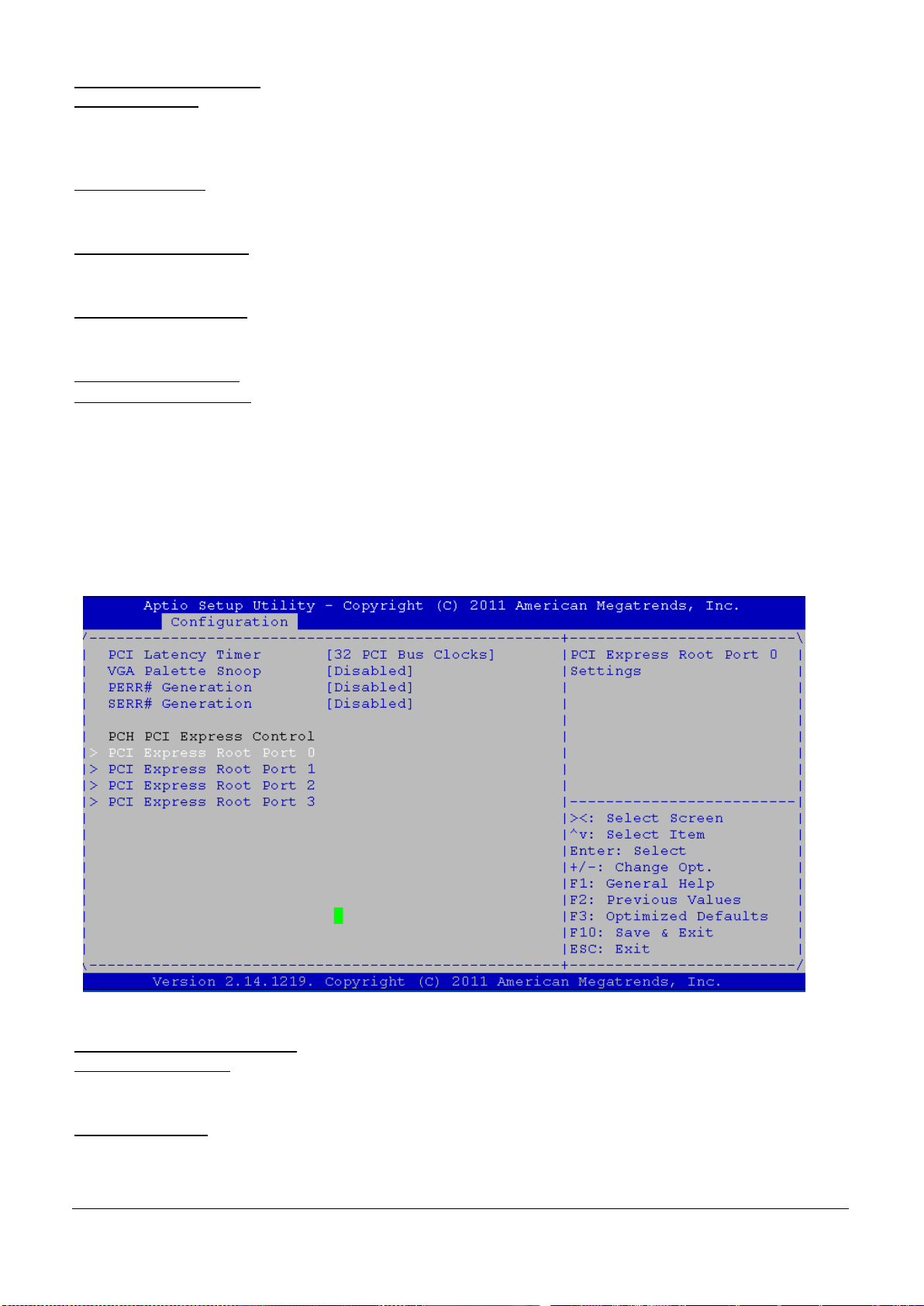
Fig. 6-16:PCI/ PCIE Configuration
PCI Latency Timer
Select value in units of PCI clocks for PCI device latency timer register.
The choice: 32 (Default), 64, 96, 128, 160, 192, 224, 248
VGA Palette Snoop
VGA Palette Registers Snooping. The Choice:Enabled or Disabled (Default).
PERR# Generation PERR#
PCI Device to Generation PERR#;The Choice:Enabled or Disabled (Default).
SERR# Generation PERR#
PCI Device to Generation SERR#;The Choice:Enabled or Disabled (Default).
PCH PCI Express Control
PCI Express Root Port 0~3
PCI Express Port 0、Port 0 IOxAPIC、UPR、FER、NFER、CER、CTO、SEFE、SENFE、SECE、PME SCI 、HOT Plug
The Choice:Enabled or Disabled (Default).
Automatic ASPM
Automatically enable ASPM based on reported capabilities and known issues.
The Choice:Manual (Default) or Auto.
Extra BUS Reserved 0; Reserved Memory 10; Reserved I/O 4;
Power Control Configuration
Enable ACPI Auto Conf
BIOS ACPI Auto Configuration. The Choice:Enabled or Disabled (Default).
Enable Hibernation
System ability to Hibernate (OS/S4 Sleep State).This option is not effective with some OS.
The Choice:Enabled or Disabled (Default).
EUDA2 Series 12”/15”/18.5” Panel PC User’s Manual (ver2.1) 33
Page 35
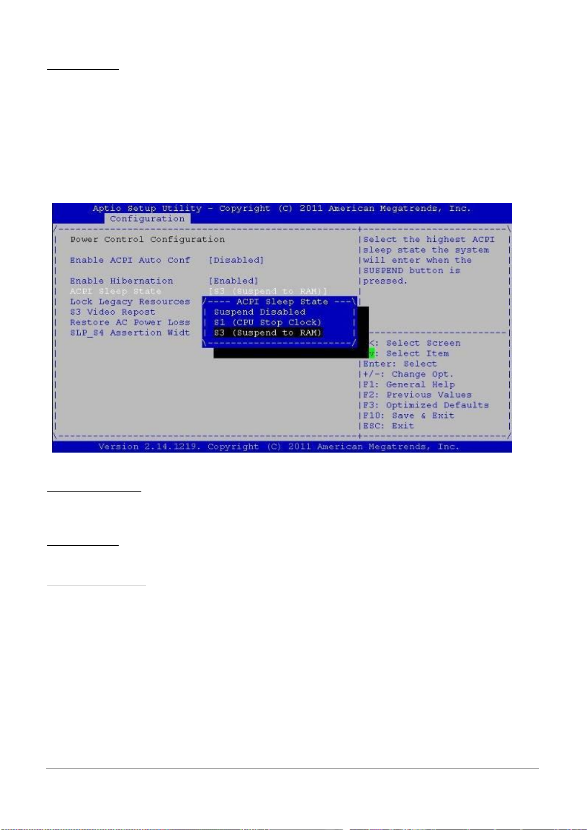
Fig. 6-17:ACPI Sleep State
ACPI Sleep State
Select for Advanced ACPI Configuration.
This item specifies the power saving modes for ACPI function. If your operating system supports ACPI, you can
choose to enter the Standby mode in S1 (POS) or S3 (STR) fashion through the setting of this field.
The Choice: [S1 (POS)] The S1 sleep mode is a low power state. In this state, no system context is lost (CPU or
chipset) and hardware maintains all system contexts.
[S3 (STR)] The S3 sleep mode is a lower power state where the information of system configuration and open
applications/ files is saved to main memory that remains powered while most other hardware components turn
off to save energy. The information stored in memory will be used to restore the system when a “wake up”
event occurs. (Default)
Lock Legacy Resource
Lock of Legacy Resource.
The Choice:Enabled or Disabled (Default).
S3 Video Repost
The Choice:Enabled or Disabled (Default).
Restore AC Power Loss
Use this option to specify what state the system returns to if there is a sudden loss of power to the system.
Choice are:
Power Off:The system remains turned off
Power On:The system turns on (Default)
Last State:DEFAULT the system returns to its previous state. If it was on, it turns itself on. If it was off, it
remains off.
EUDA2 Series 12”/15”/18.5” Panel PC User’s Manual (ver2.1) 34
Page 36
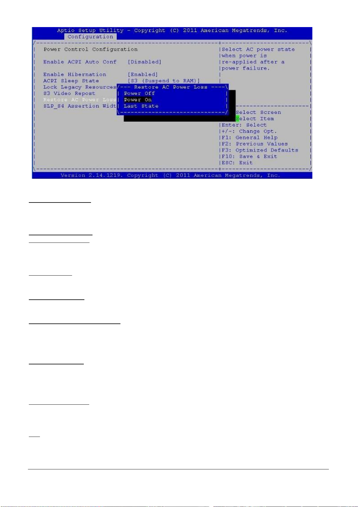
Fig. 6-18:Restore AC Power Loss
SLP S4 Assertion Width
Select a minimum assertion width of the SLP_S4# signal
The Choice:1-2 Seconds (Default); 2-3 Seconds; 3-4 Seconds; 4-5 Seconds
S5 RTC Wake Setting
Wake system with Fixe
System wakes on alarm event. When enabled System will wake on the hr:min:sec. specified.
The Choice:Enabled or Disabled (Default)
Wake up by ring
Wake up by ring from S5.The Choice:Enabled or Disabled (Default)
CPU Configuration
These items show the advanced specifications of your CPU. Read only.
Hyper Threading Technology(HTT)
“Enabled” for Windows XP and Linux (OS optimized for Hyper-Threading Technology) and “Disabled” for other
OS (OS not optimized for Hyper-Threading Technology).
The choice: Enabled or Disabled (default).
Execute-Disable Bit
XD can prevent classes of malicious buffer overflow attacks when combined with a supporting OS(Window
Server 2003 SP1,Windows XP SP2, SuSE Linux 9.2, RedHat Enterprise 3 Update 3.)
The choice: Enabled or Disabled (default).
Limit CPUID Maximum
Disabled for Windows XP
The choice: Enabled or Disabled (Default).
EIST
Intel SpeedStep
The choice: Enabled or Disabled (Default).
EUDA2 Series 12”/15”/18.5” Panel PC User’s Manual (ver2.1) 35
Page 37
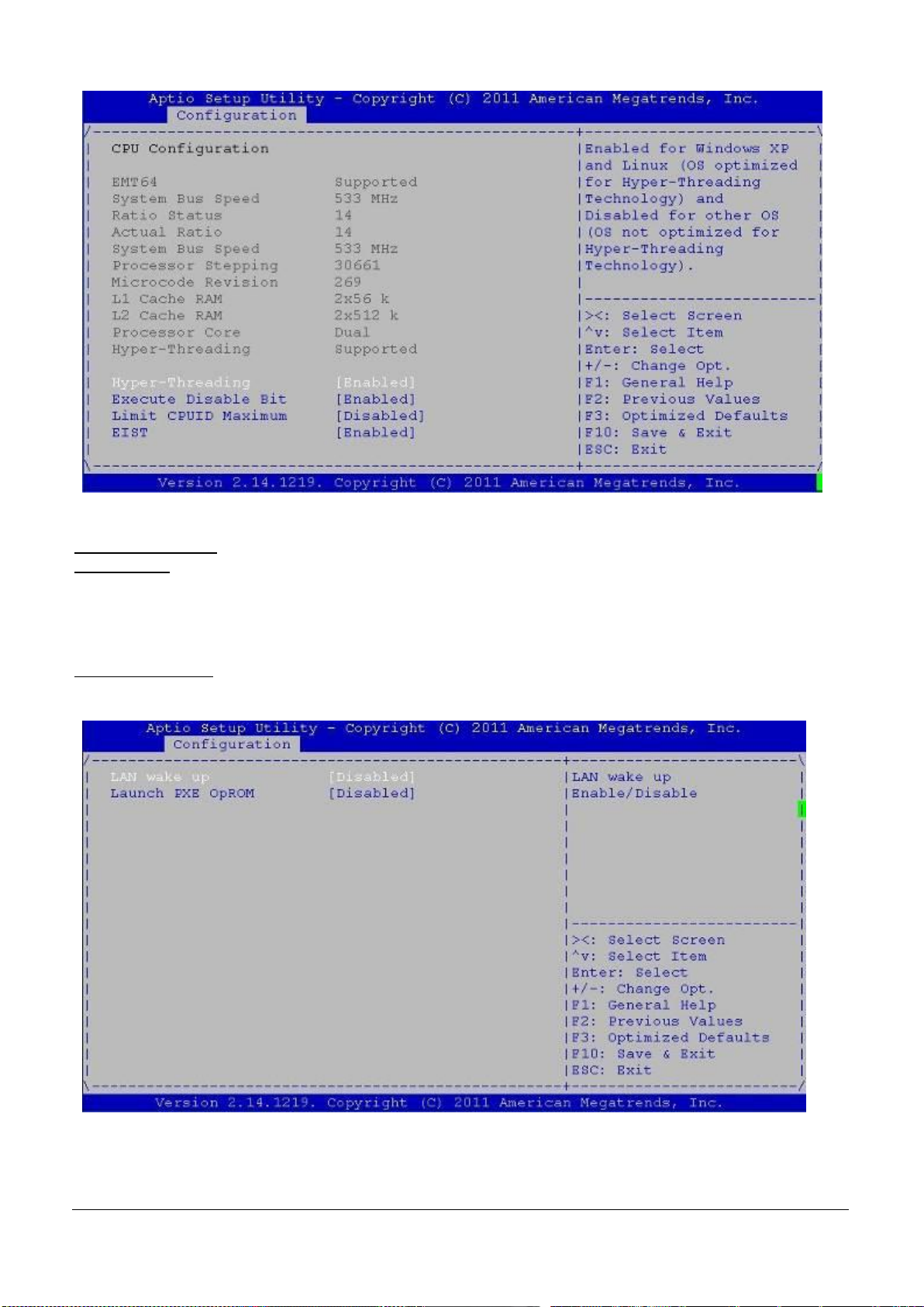
Fig. 6-19:CPU Configuration
Fig. 6-20:LAN Configuration
LAN Configuration
LAN Wake Up
This field specifies whether the system will be awakened from the S5 .power saving mode when activity or
input signal of onboard LAN is detected.
The choice: Enabled or Disabled (Default).
Launch PXE OpROM
Use this option to select Enabled or Disabled (Default) option for Legacy Network Devices.
EUDA2 Series 12”/15”/18.5” Panel PC User’s Manual (ver2.1) 36
Page 38
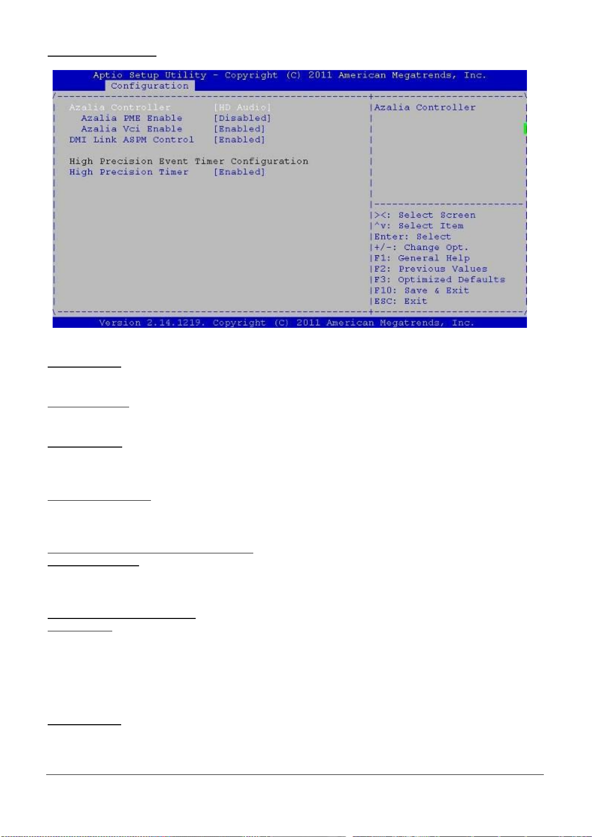
Chipset Configuration
Fig. 6-21:Chipset Configuration
These items show the advanced specifications of your CPU. Read only.
Azalia Controller
Azalia Controller: HD Audio (Default).
Azalia PME Enable
Power management capability of Audio Controller. The choice: Enabled, Disabled (Default).
Azalia Vci Enable
Azalia Supports 1 extended VC, which, When enabled, overrides ICH VCp settings.
The choice: Enabled or Disabled (default).
DMI Link ASPM Control
The control of Active State Power management on both NB side and SB side of the DMI Link
The choice: Enabled or Disabled (default).
High Precision Event Timer Configuration
High Precision Timer
High Precision Event Timer
The choice: Enabled or Disabled (default).
Integrated IGD Configuration
IGD-Boot Type
Use this option to select the display device used by the system when it boots. Configuration options are listed
below.
CRT
LVDS (Default)
CRT+LVDS
LVDS Panel Type
Select the Video Device which will be activated during POST. This has no effect if external graphics present.
Configuration options are listed below.
EUDA2 Series 12”/15”/18.5” Panel PC User’s Manual (ver2.1) 37
Page 39

640 x 480
24Bit 800 x 600
24Bit 1024 x 768
24Bit 1280 x 1024
24Bit
Note: The LVDS Panel Type setting in BIOS setup is invalid due to Hardware design.
Please refer to fig.6-4 for different resolution setting by SW1 of board.
Panel Scaling
Select the LCD Panel Scaling option used by the Internal Graphic Device.
The choice: Auto (Default), Force Scaling, Off, Maintain Aspect Ratio.
Backlight Control
Back Light Control Setting
The choice: PWM Inverted, GMBUS Inverted, PWM Normal (Default), GMBUS Normal.
Active LEP
Use this option to select the Active LFP configuration
The choice:
No-LVDS: VBIOS does not enable LVDS.
Internal-LVDS: VBIOS enables LVDS driver by integrated encoder. (Default)
IGD Clock Source
Use this option to select the IGD Clock
The choice: External Clock (Default); Internal Clock.
Fixed Graphic Memory
Configure Fixed Graphic Memory Size. Configuration options are listed:128 MB (Default); 256 MB.
ALS Support
Valid only for ACPI Legacy=ALS Support through the IGD INT10 function. ACPI=ALS support through an ACPI ALS
driver.
The choice: Enabled, Disabled (Default).
Backlight Control Support
Backlight Control Configuration.
The choice: VBIOS (Default); BLC&BIA Disabled; BLC Enabled.
BIA
The choice:
Auto:GMCH Use VBT (Default).
Level n:Enabled with Selected Aggressiveness Level
EUDA2 Series 12”/15”/18.5” Panel PC User’s Manual (ver2.1) 38
Page 40
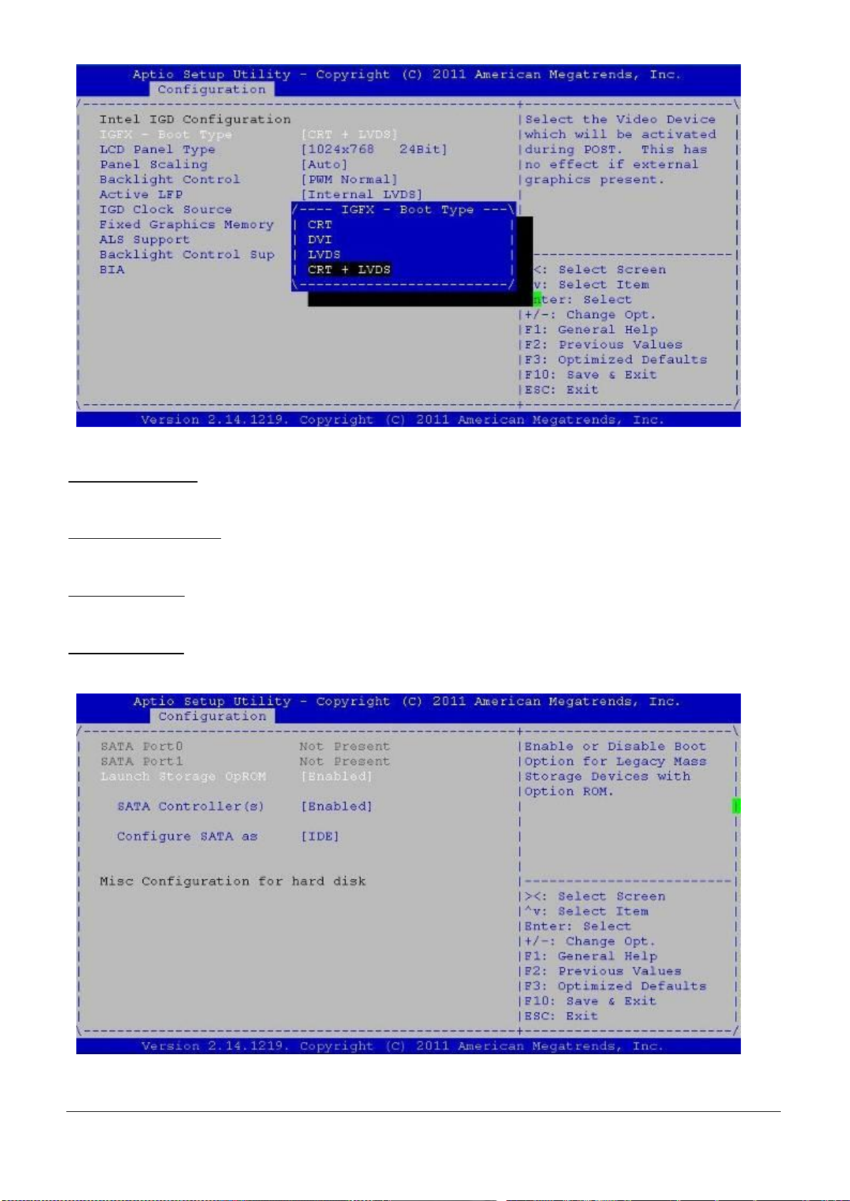
Fig. 6-22:Integrated Video Configuration
Fig. 6-23:IDE Configuration
IDE Configuration
It uses a separate sub menu to configure each hard disk drive.
Launch Storage OpROM
The choice: Disabled, Enabled (Default).
SATA Controller(s)
The choice: Disabled, Enabled (Default).
Configure SATA as
The choice: IDE Only (Default).
EUDA2 Series 12”/15”/18.5” Panel PC User’s Manual (ver2.1) 39
Page 41
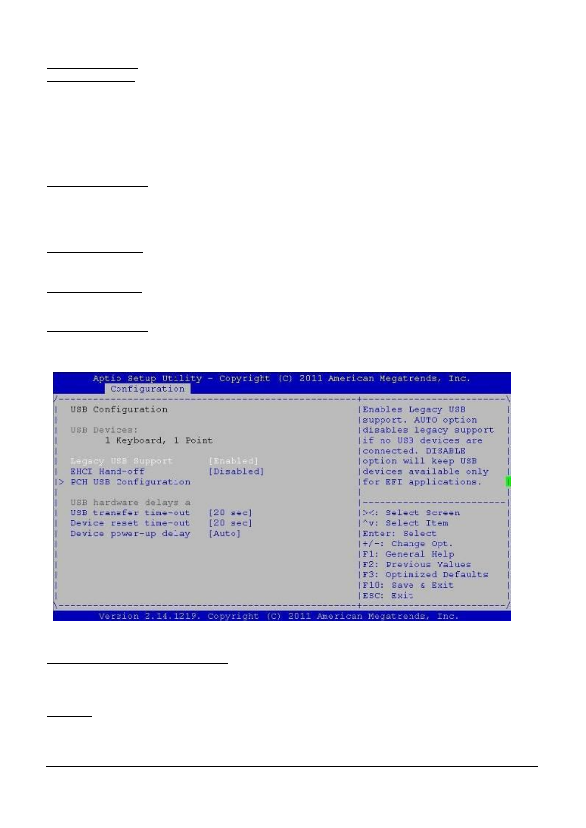
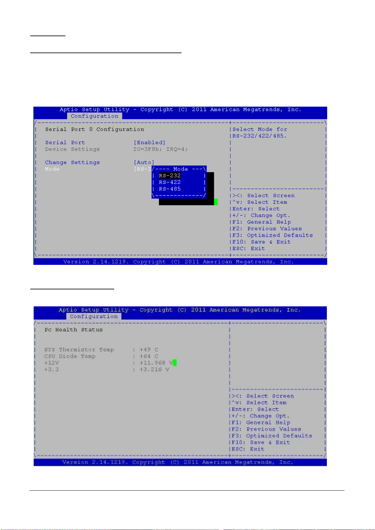
Fig. 6-24:USB Configuration
USB Configuration
Legacy USB Support
Enables Legacy USB support. AUTO option disables legacy support if no USB devices are connected. Disable
option will keep USB devices available only for EFI application. The choice: Enabled or Disabled (Default).
EHCI Hand-Off
This is a workaround for OS without EHCI hand-off support. The EHCI ownership change should claim by EHCI
driver. The choice: Enabled or Disabled (Default).
PCH USB Configuration
PCH USB Configuration setting.
USB hardware delays a
USB transfer time-out
The time-out value for Control, Bulk, and Interrupt transfers. The choice: 20 sec (Default).
Device reset time-out
The time-out value for Control, Bulk, and Interrupt transfers. The choice: 20 sec (Default).
Device power-up delay
Maximum times the device will take before it properly reports itself to the Host Controller. ”Auto” (Default) uses
default value for a Root port it is 100ms, for a Hub port the daily is taken from Hub descriptor.
W83627UHG Super IO Configuration
This System is using Super IO Chip: W83627UHG, there are Port0~port3 COM port for selection.
When you select Port 0,1,2 or 3, the relational contents are as below:
CaseOpen:The choice: On/Off (Default).
EUDA2 Series 12”/15”/18.5” Panel PC User’s Manual (ver2.1) 40
Page 42
WDT Timer: WDT Timer; EHCI driver. The choice: Enabled or Disabled (Default).
Fig. 6-25:W83627UHG Serial Port 1 Configuration
Fig. 6-26:H/W Monitor Configuration
Serial Port (Selectable COM port mode through BIOS )
Enable (Default) or disable Serial Port (COM).
Device Setting :IO=3F8h;IRQ=4(Default);
Change Setting:Auto (Default);
Mode:Select for COM port (COM1 & COM2 only) mode RS-232 (Default), RS-422 or RS-485.
Device Mode:Standard Serial Port Mode (Default) ; IrDA 1.0 (HP SIR) Mode; ASKIR Mode.
W83627UHG H/W Monitor
This function is a real-time detecting system status for CPU temperture, System temperture, relational Volts
(12V, 3.3V)
EUDA2 Series 12”/15”/18.5” Panel PC User’s Manual (ver2.1) 41
Page 43
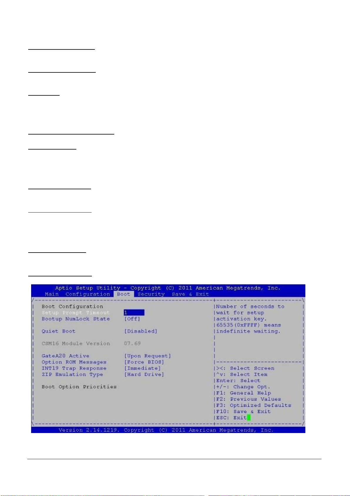
Fig. 6-27:Boot
6.4.4 Boot
Setup Prompt Timeout
Number of seconds to wait for setup activation key.65535 (0xFFFF) means indefinite waiting.
Bootup NumLock State
Select the Keyboard NumLock state. The choice: On, Off (Default).
Quiet Boot
Use this option to select the screen display when the system boots. The choice:
Disabled Normal POST messages displayed (Default).
Enabled OEM Logo displayed instead of POST messages.
CSM16 Module Version 07.69
GateA20 Active
The choice:
UPON REQUEST:GA20 can be disabled using BIOS Services.
ALWAYS:do not allow disabling GA20; this option is useful when any RT code is executed above 1MB.
Option ROM Message
Set display mode for option ROM;The choice: Force BIOS (Default);Keep Current.
INT19 Trap Response
BIOS reaction on INT19 trapping by Option ROM:The choice:
Immediate:execute the trap right away;
Post Pond:execute the trap during legacy boot.
ZIP Emulation Type
Sets the Emulation type for ZIP Drivers;The choice: Floppy (Default), Hard Drive
Boot Option Priorities
EUDA2 Series 12”/15”/18.5” Panel PC User’s Manual (ver2.1) 42
Page 44
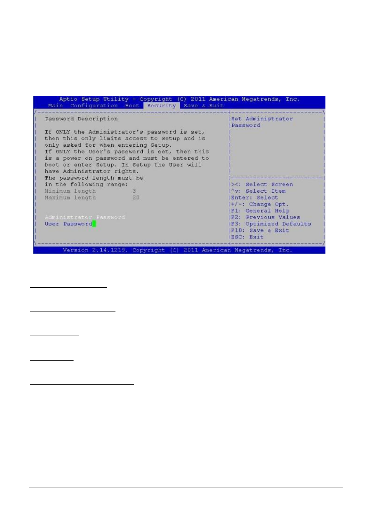
6.4.5 Security
Fig. 6-28:Security
Use the Security option to set Administrator and user passwords.
If only the administrator’s password is set, there will only be access to Setup and will only asked for when
entering Setup.
If only the user’s password is set, then this is power-on password and must be entered to boot or enter Setup.
In setup the user will have Administrator Rights.
6.4.6 Save and Exit
Save Changes and Reset
Reset the system after saving the changes.
Discard Changes and Reset
Reset system setup without any saving any changes.
Restore Default
Restore/Load Default values for all the Setup Option.
Boot Override
SATA: HDD (Default)
Launch EFI Shell from fileSystem
Attempts to Launch EFI Shell application (Shellx64.efi) from one of the available fileSystem devices.
EUDA2 Series 12”/15”/18.5” Panel PC User’s Manual (ver2.1) 43
Page 45
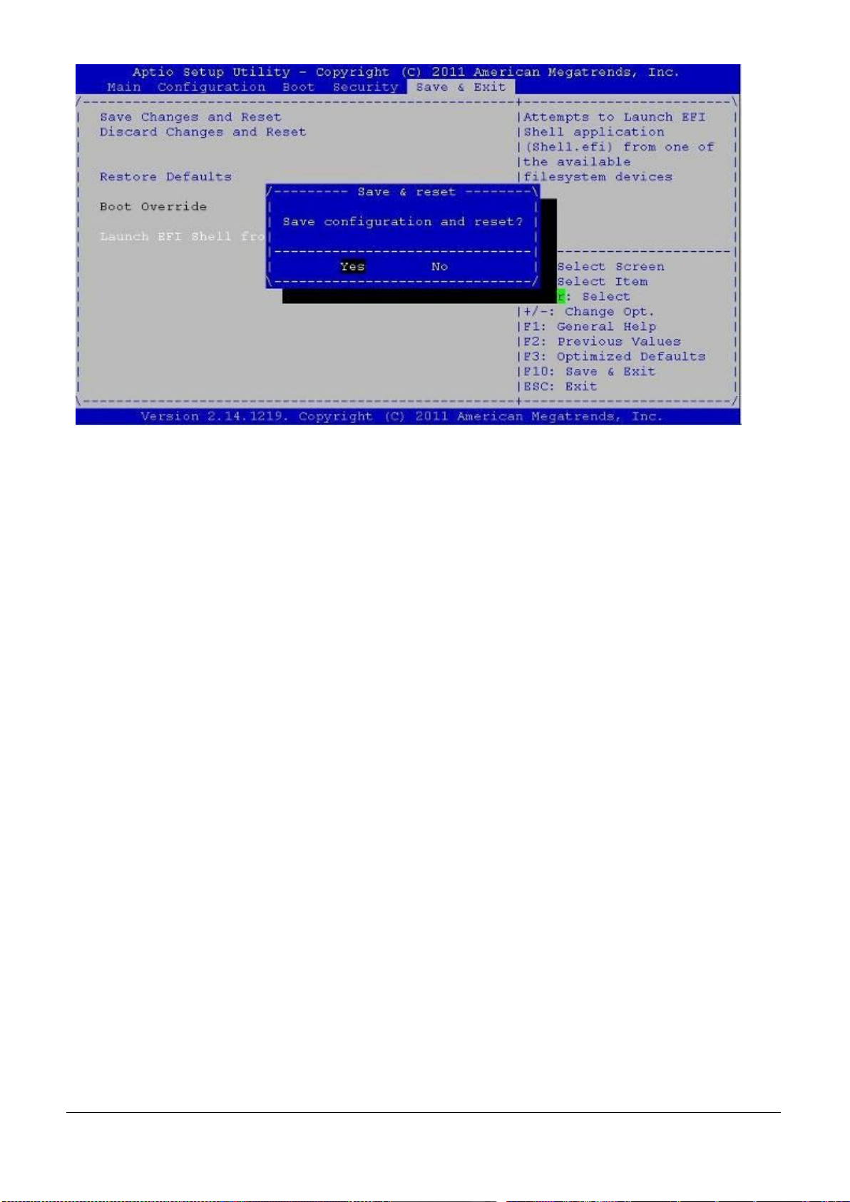
Fig. 6-29:Save and Exit
EUDA2 Series 12”/15”/18.5” Panel PC User’s Manual (ver2.1) 44
Page 46
Driver Installation and Touch Usage Guide
7. Driver Installation and Touch Usage Guide
7.1 Driver Installation
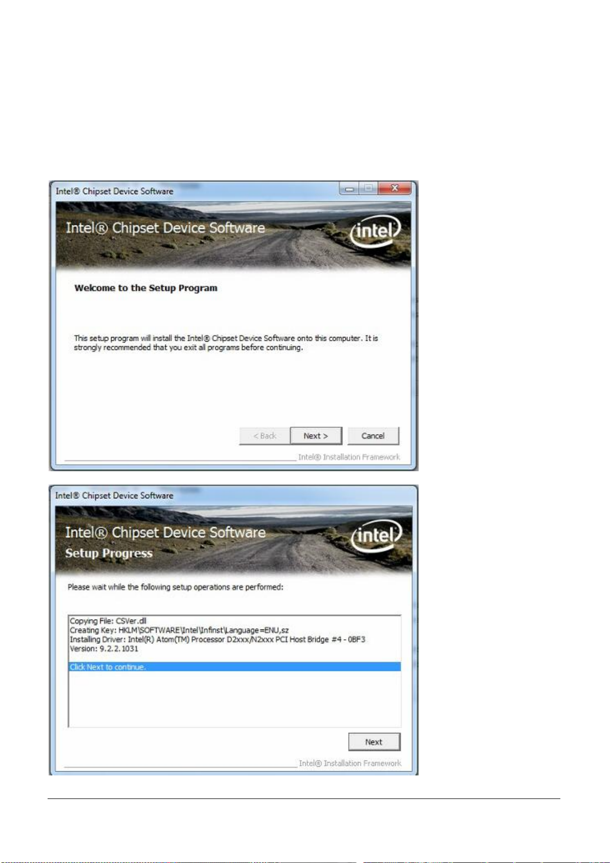
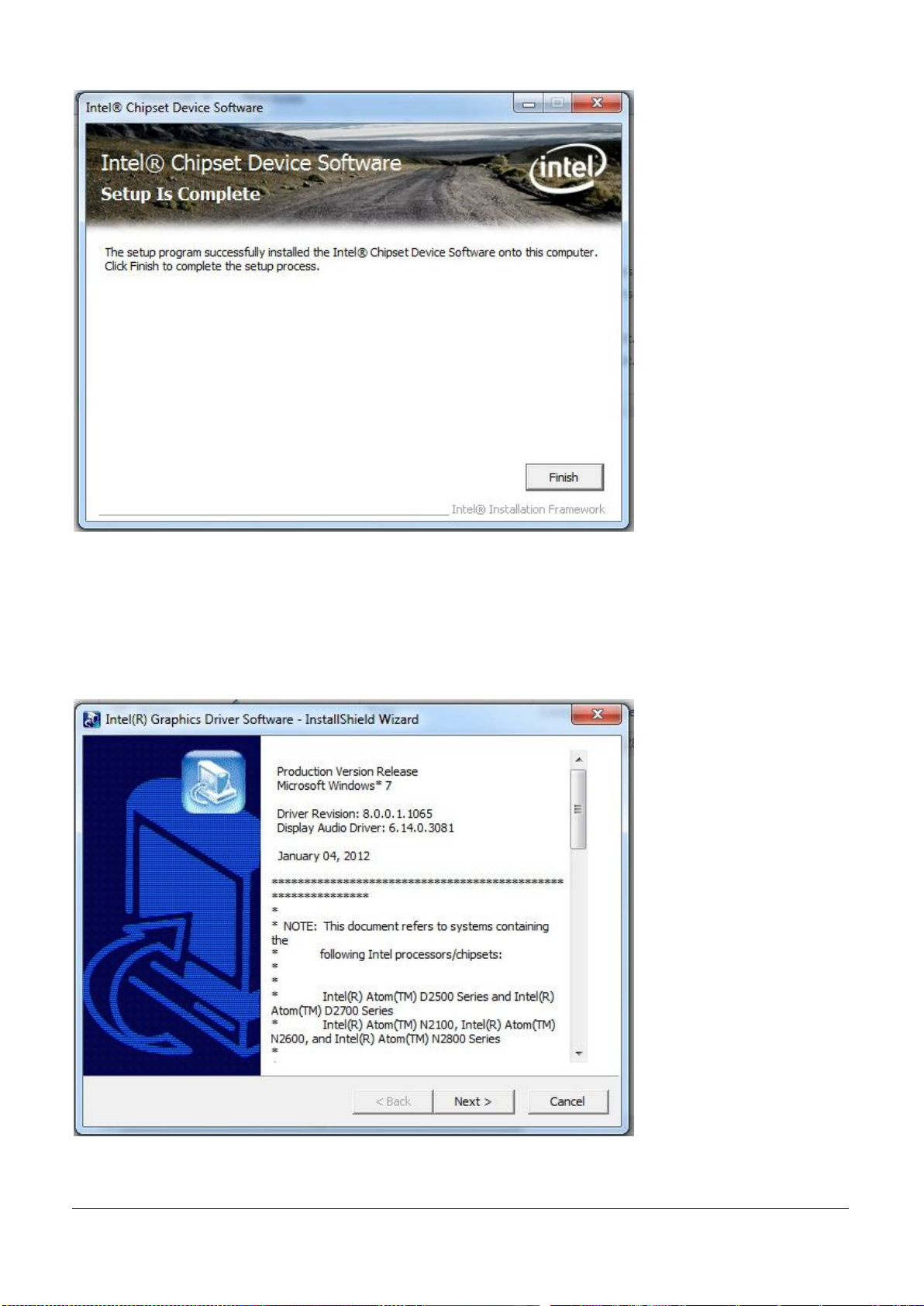
7.1.1 Chipset Component Driver
The chipset on the EUDA2 Panel PC Series system is an Intel new chipset that a few old operating systems might
not be able to recognize. To overcome this compatibility issue, for Windows Operating Systems such as
Windows 7, please install its INF driver before any other driver installation. You can easily find the chipset
component driver in EUDA2&FUDA Series Driver CD Win7 (32bit)-title.
EUDA2 Series 12”/15”/18.5” Panel PC User’s Manual (ver2.1) 45
Page 47
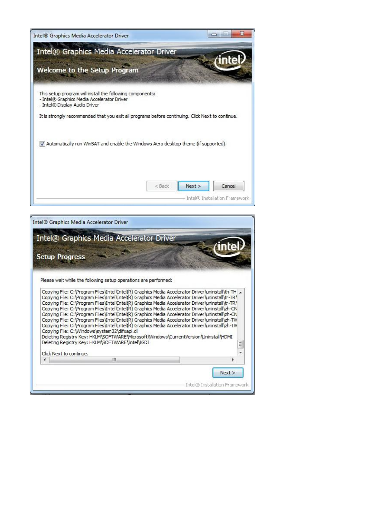
7.1.2 Intel® Integrated GMCH Graphics Driver Installation
The Intel ® Atom™ Processor D2550 contains an integrated graphics core, the Intel ® GMA 3650 graphics
controller. This combination makes EUDA2 Panel PC Series system an excellent piece of multimedia hardware,
EUDA2-S1220/EUDA2-S1520/EUDA2-S1821 supports VGA, DP and also LVDS out put. The VGA port supports
analog displays. The maximum supported resolution is 1920 x 1200 (WUXGA) at a 60 Hz refresh rate. VGA port
enabled from POST whenever monitor is connected.
EUDA2 Series 12”/15”/18.5” Panel PC User’s Manual (ver2.1) 46
Page 48
Drivers Support
Please find Intel® GMA 3650 driver in EUDA2&FUDA Panel PC Series Driver CD Win7 (32bit)-title. The driver
supports Windows 7 only.
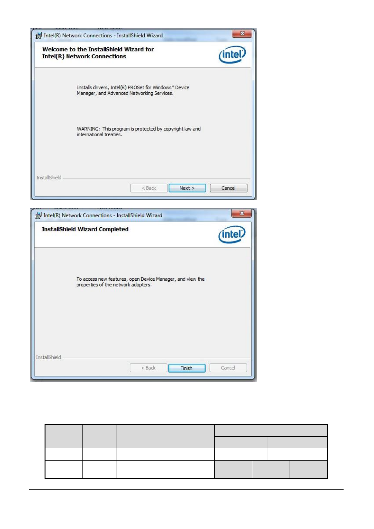
7.1.3 Intel Gigabit Ethernet Driver Installation
Drivers Support
Please find Intel 82574L Ethernet driver in EUDA2&FUDA Panel PC Series CD Win7 (32bit)-title. The driver
supports Windows 7.
EUDA2 Series 12”/15”/18.5” Panel PC User’s Manual (ver2.1) 47
Page 49
82574L
Color
Name of LED
Operation of Ethernet Port
Linked
Active
Status LED
Yellow
LAN Linked & Active LED
On
Blinking
Speed LED
Orange &
Green
LAN speed LED
Giga Mbps
100 Mbps
10 Mbps
LED Indicator
The EUDA2 Panel PC Series system, EUDA2-S1220/EUDA2-S1520/EUDA2-S1821, provides two LED indicators to
report Intel 82574L Gigabit Ethernet interface status. Please refer to the table below as a quick reference guide.
EUDA2 Series 12”/15”/18.5” Panel PC User’s Manual (ver2.1) 48
Page 50
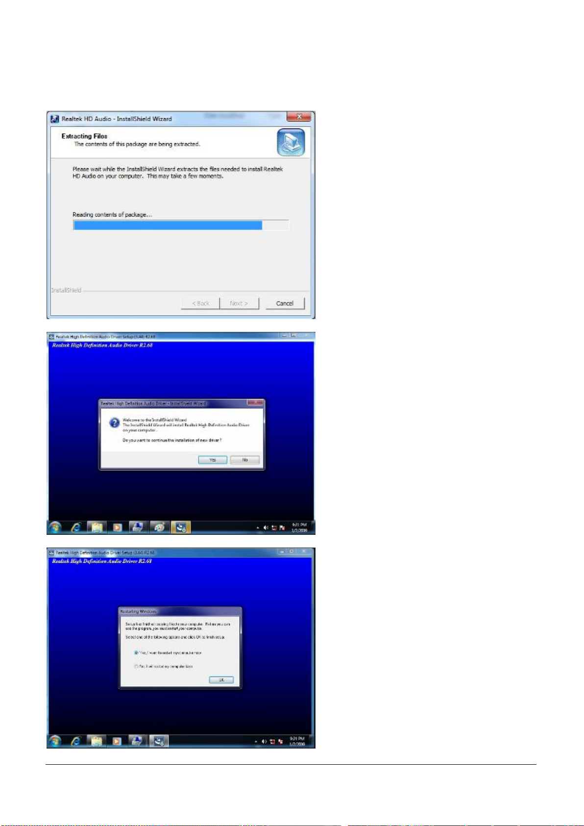
7.1.4 Audio Controller Driver Installation
Please find Realtek ALC886-GR Audio driver form EUDA2&FUDA Series Driver CD Win7 (32bit)-title. The driver
supports Windows 7.
EUDA2 Series 12”/15”/18.5” Panel PC User’s Manual (ver2.1) 49
Page 51
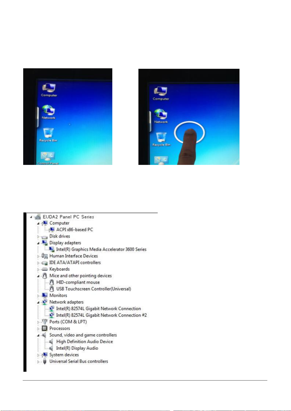
7.1.5 Touch Controller Driver Installation
P-CAP is support by Windows 7
The P-CAP controller can be detected by Windows 7 without driver installation and calibration.
You can use your finger to make sure touch point is exact as below.
7.2 Device Function Verification
After all of driver installation, please make sure all of devices on the EUDA2 Panel PC Series system,
EUDA2-S1220/EUDA2-S1520/EUDA2-S1821, are without yellow mark exclamation on device manager and test
them according to relative testing tool.
EUDA2 Series 12”/15”/18.5” Panel PC User’s Manual (ver2.1) 50
Page 52
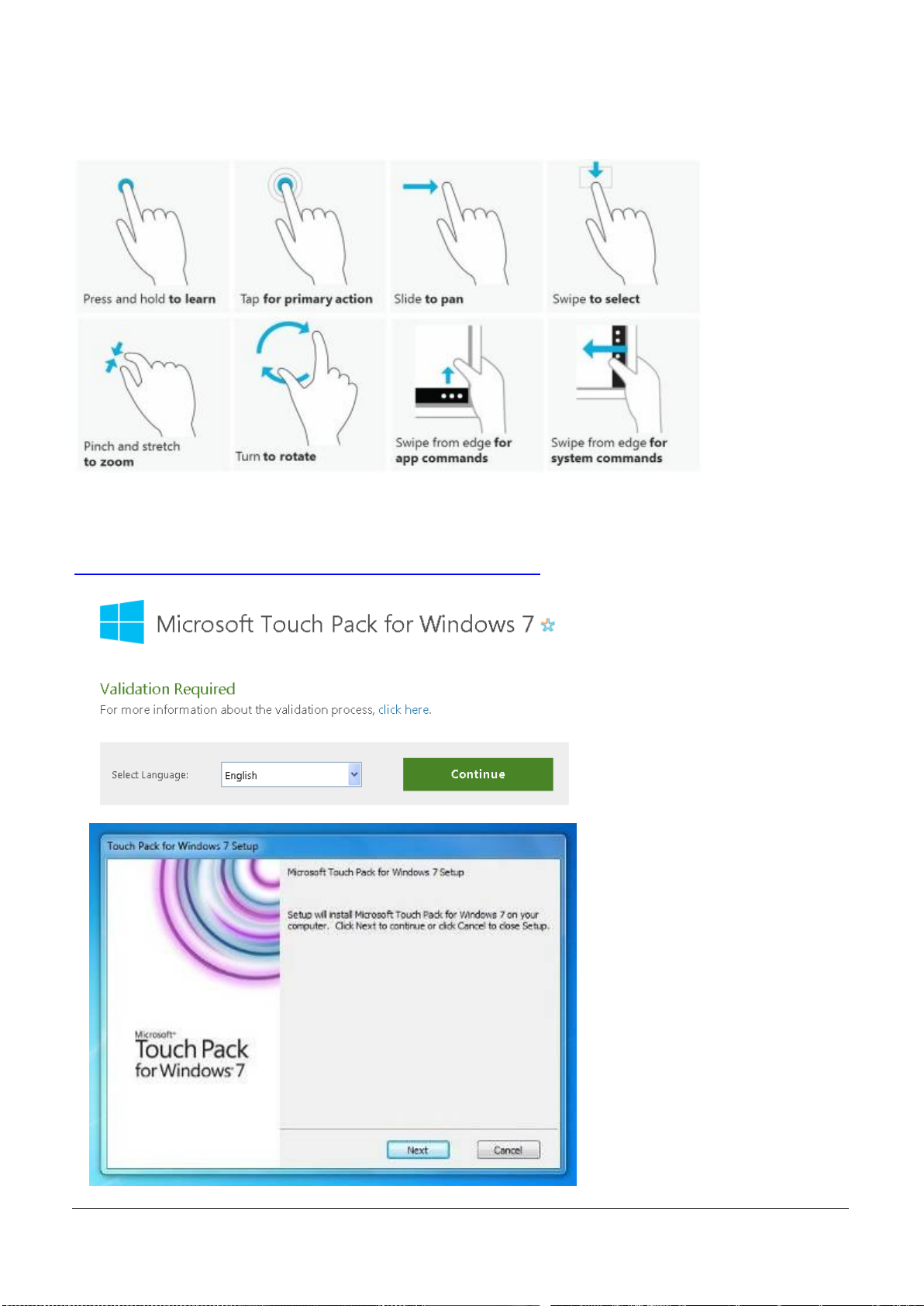
7.3 Windows 7 gesture for multi-touch demand
Windows Touch Pack for windows 7
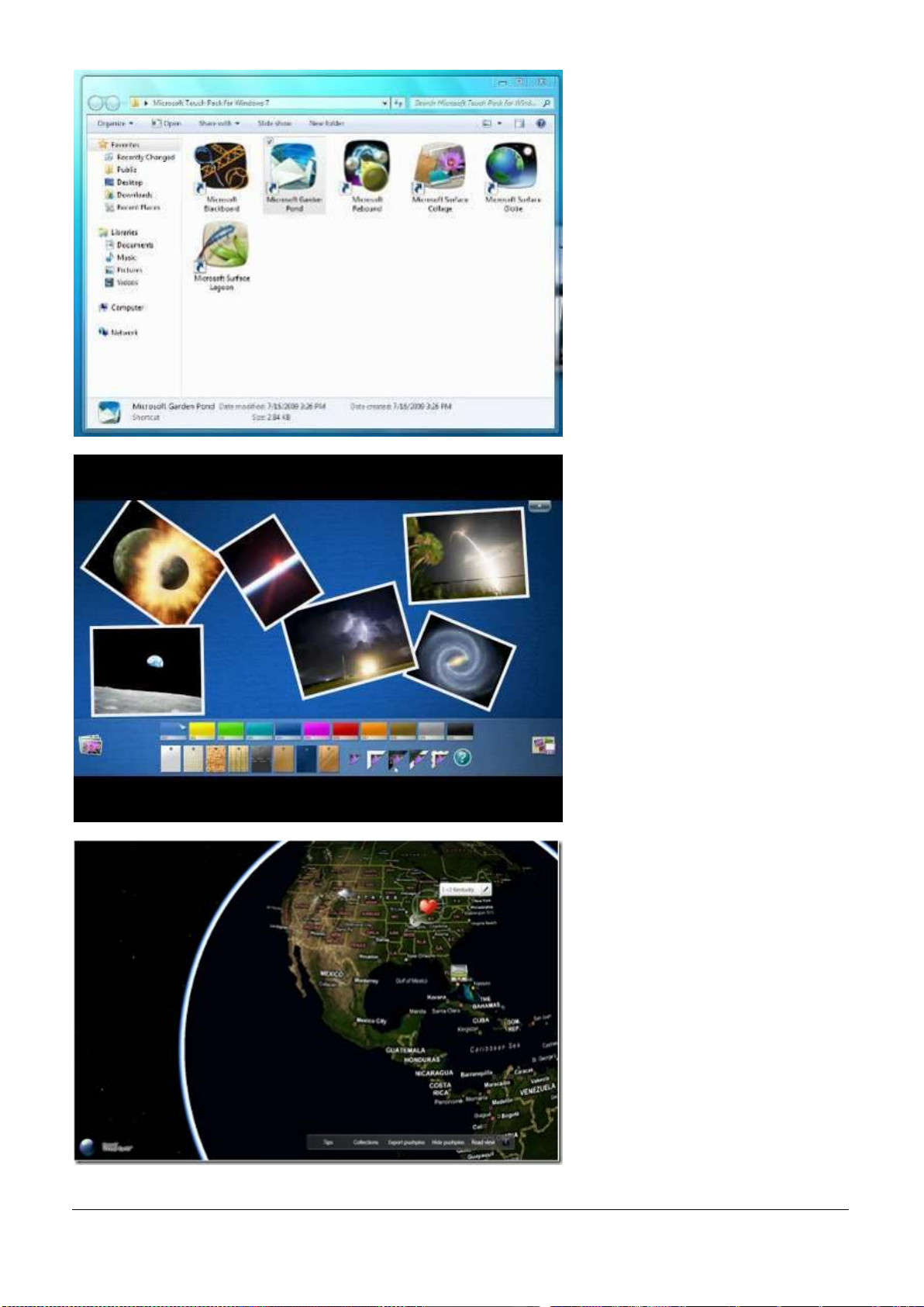
For multi-touch application, please download Windows Touch Pack for windows 7 from the following link to
learn more usage of multi-touch.
http://www.microsoft.com/en-us/download/details.aspx?id=17368
EUDA2 Series 12”/15”/18.5” Panel PC User’s Manual (ver2.1) 51
Page 53
EUDA2 Series 12”/15”/18.5” Panel PC User’s Manual (ver2.1) 52
Page 54
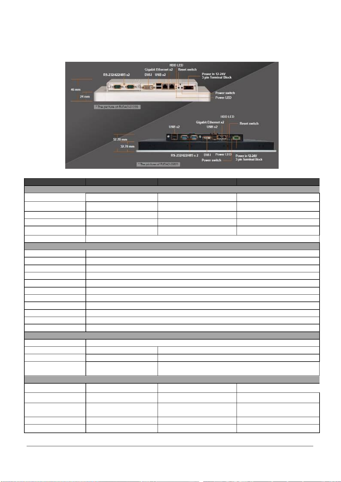
Technical Data
Model Name
EUDA2-S1220
EUDA2-S1520
EUDA2-S1821
Display
LCD Size
12” (4:3)
15” (4:3)
18.5” (16:9)
Resolution
800 X 600
1024 X 768
1366 X 768
Brightness
450 cd/m2
400 cd/m2
300 cd/m2
Contrast Ratio
700:1
700:1
1000:1
Backlight
LED type
LED type
LED type
Touch screen
Projected Capacitive Touch (2 point support)
System
CPU
Intel Atom Dual-Core D2550 1.86 GHz
Chipset
Intel NM10
Memory
One DDR3 SO-DIMM SDRM 800/1066 MHz max up to 4GB
BIOS
AMI BIOS
Graphics
Intel GMA 3650 Graphics
LVDS
Dual Channel 24-bit
LAN Chipset
Dual Intel 82574L Gigabit Ethernet
Audio
Realtek High Definition Audio
Watchdog Timer
Programmable via SW from 0.5 sec to 255 min
Storage Device
2.5" SATA HDD/2.5" SATA SSD/ Compact Flash Type II
Operating System
Windows 7 /XP Pro/WES 7/XPe/Linux supported
I/O interface
Main board
2xGigabit Ethernet, 2xUSB, 1xDVI-I (Default)
Expansion (default)
2xRS-232/422/485
2xRS-232/422/485, 2xUSB (Default)
Expansion (option1)
1xRS-232/422/485, 2xUSB
2xRS-232/422/485, 1xRS-232 (Optional)
Expansion (option2)
1xLine-out,
1xRS-232/422/485
1xLine-out, 1xRS-232/422/485, 2xUSB (Optional)
Mechanical
Dimension
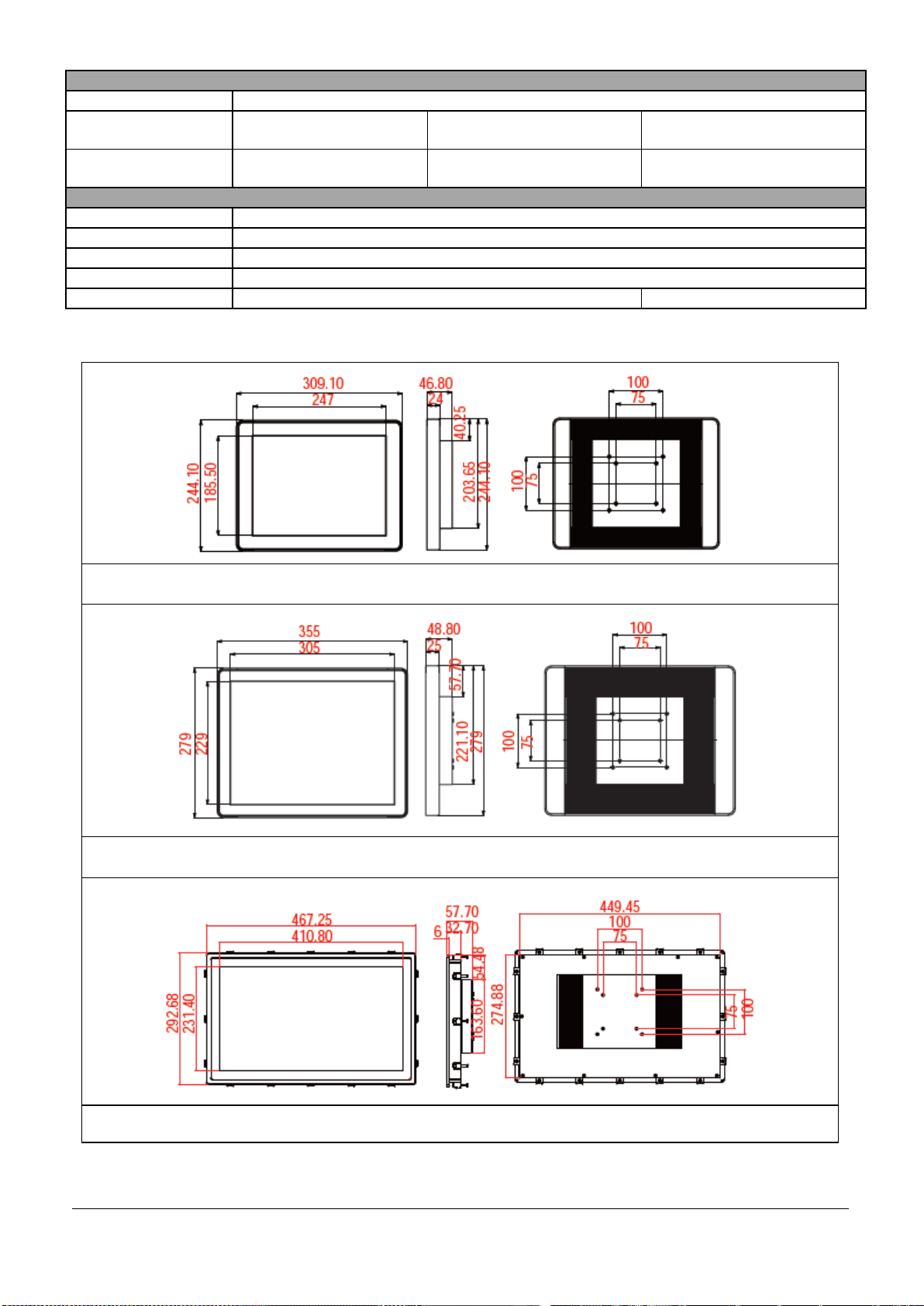
309.1 x 244.1 x 46.8 mm
355 x 279 x 48.8 mm
463.3 x 288.7 x 57.7 mm
Cut-out Dimension
N/A
N/A
451.45 x 276.88 mm
Mounting
VESA Mount
75 x 75, 100 x 100
VESA Mount
75 x 75, 100 x 100
Panel mount & VESA Mount
75 x 75, 100 x 100
Weight
3.8 KG
4.0 KG
6.8 KG
Carton Weight
5.8 KG
7.0 KG
9.7 KG
8. Technical Data
8.1 Product Specification
EUDA2 Series 12”/15”/18.5” Panel PC User’s Manual (ver2.1) 53
Page 55
Power
Power Supply
DC 12 ~ 24V input (with 3 pin terminal block connector)
Power Consumption
(Max)
35W(12V); 36W(24V)
39.2W(12V); 40W(24V)
45.1W(12V); 44.6W(24V)
Power Consumption
(Min)
7.1W(12V); 7.9W(24V)
7.3W(12V); 7.9W(24V)
8.4W(12V); 7.7W(24V)
Environmental
OP /Storage Temp
0 ~ 50 ℃;-20~60 ℃;(20~90%, non-condensing)
Vibration
1.0G (CF) and 0.5G (HDD) @ Power on testing & Packaged;5~500Hz, 2.16G
Shock
15G peak acceleration,11 ms (Power on condition)
Drop
Packaged with Carton from 96.5cm (1-Corner, 3-Axis, 6-Face)
IP Protection
IP54 (Front) / IP20 (Rear) (IEC 60529 Edition 2.1 Standard)
IP54 (Front) / IP20 (Rear)
Fig 7-1:Front View/ Right-side View/ Rear View of EUDA2-S1220 Panel PC System
Fig 7-2:Front View/ Right-side View/ Rear View of EUDA2-S1520 Panel PC System
Fig 7-3:Front View/ Right-side View/ Rear View of EUDA2-S1821 Panel PC System
8.2 Mechanical Specification
EUDA2 Series 12”/15”/18.5” Panel PC User’s Manual (ver2.1) 54
Page 56

EMC
Standards
CE
EN 55022/55024:2010 Class A
EN 61000-3-2:2006+A2:2009
EN 61000-3-3:2008
AS/NZS CISPR 22:2009+A1:2010
FCC
FCC 47 CFR Part 15B, Class A, CISPR:2008
ANSI C63.4:2009, ICES-003 Issues 4:2004,Class A
8.3 Certifications and Standards
EUDA2 Series 12”/15”/18.5” Panel PC User’s Manual (ver2.1) 55
Page 57

RMA (Return Material Authorization) Service
9. RMA (Return Material Authorization) Service
Before returning any goods, please:
1. Contact Portwell Support and request a RMA number (Return Material Authorization).
2. Describe the behavior or reason of unit failure in order to return. Any returns for credit are subject to a
restocking fee.
3. Upon confirmation of a hardware failure or valid cause for return, Portwell will provide a Return Merchandise
Authorization (RMA).
4. Make sure to receive an RMA number from Portwell before returning any merchandise. Clearly write or mark
this number on the outside of the package you are returning. Any returns without an authorization will be
refused and returned to you by the shipper.
5. When returning goods, include the name and telephone number of a person whom we can contact for
further explanations if necessary. Where applicable, always include all duty papers and invoice(s) associated
with the item(s) in question:
Ensure that the unit is properly packaged in the original box. A product packaging manual will be included
with the replacement Panel or can be emailed to you in advance. Please refer to it for the necessary
instructions on how to appropriately package the panel computer being returned. Failure to do so may result in
the panel shifting during transit – which may result in physical damage. Physical damage from improper
packaging will void your system warranty.
Ship the panel back to the address provided on the RMA documentation, via an insured carrier with freight
pre-paid.
Return unit must be received to address provided within 30 days, or invoice for full amount of Panel PC will be
issued.
EUDA2 Series 12”/15”/18.5” Panel PC User’s Manual (ver2.1) 56
Page 58
FAQs (Frequent Asked Questions)
10. FAQs (Frequent Asked Questions)
Q1: What is the 64-bit Windows 7 support status?
Answer:
No graphics driver is available for 64-bit Windows 7 on Intel Atom Dual-Core D2550 platform.
Q2: What is the Window 8 support status?
Answer:
No graphics driver is available for Windows 8 on Intel Atom Dual-Core D2550 platform.
Q3: What is the Windows XP support status?
Answer:
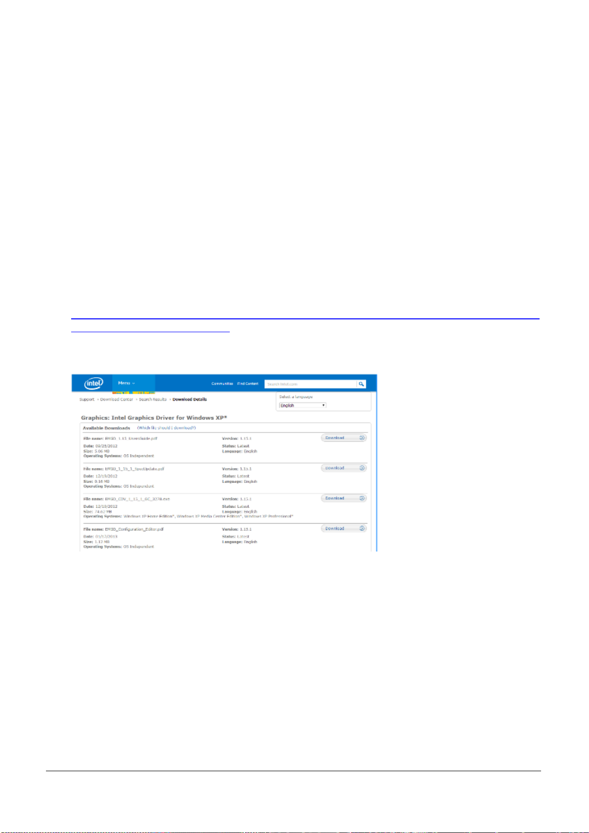
For Windows XP support on EUDA2 & FUDA series PPC (Intel Atom D2550 platform), please visit Intel
EMGD website from the following link:
http://www.intel.com/content/www/us/en/intelligent-systems/intel-embedded-media-and-graphics-drive
r/emgd-for-intel-atom-systems.html
After EMGD driver download finished, please configure the display setting to generate the driver
according to your requirement, ex. LVDS only or LVDS + VGA, then install it on Windows XP.
Q4: What is the Windows XP media acceleration support status?
Answer:
The graphics driver for Windows XP does not include hardware acceleration for media on EUDA2 & FUDA
Series PPC system (Intel Atom D2550 platform).
Q5: Why P-CAP touch multi-touch function doesn’t work properly under Linux OS?
Answer:
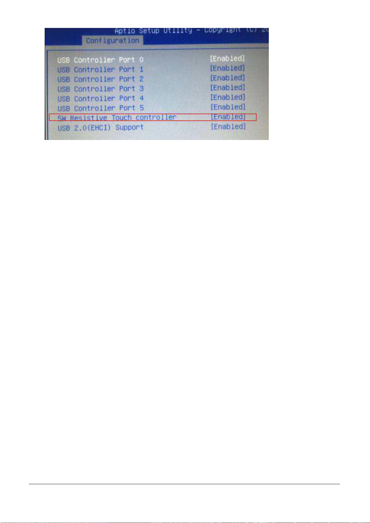
5W Resistive Touch controller circuit has been built-in the system and is set to “Enabled” status under
BIOS setup. It might interference multi-touch function working properly with some of Linux Operating
System distribution.
So please set “5W Resistive Touch controller” item from [Enabled] to [Disabled] under BIOS setup as
below figure.
EUDA2 Series 12”/15”/18.5” Panel PC User’s Manual (ver2.1) 57
Page 59
EUDA2 Series 12”/15”/18.5” Panel PC User’s Manual (ver2.1) 58
 Loading...