

PORTMAN GV8300 Installation Manual

1
GPS&GPRS CAR ALARM GV8300
INSTALLATION MANUAL
1
REV: 1.6 (Series, GV8300V1.20, GV8300-C2)
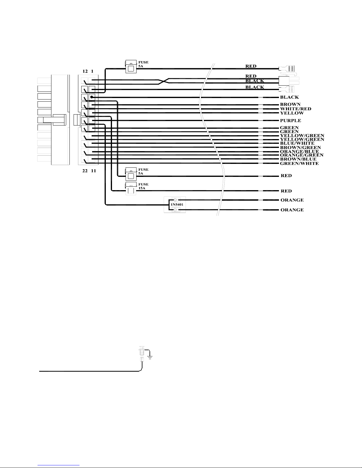
Connectors detail description
H1 2*11 connector
H1/1&H1/12:
The other terminal of the two wires is a 2PIN connector; it is very convenience to connect the solar battery board.
The solar battery board is optional; it means that if there is no solar battery board to connect, GV8300 can still work.
H1/2&H1/13:
The other sides of the two wires have especial terminal that can insert the backup battery terminal directly, the
backup battery is necessary, and it can power the GV8300 when the 12V power supply is off.
H1/3:Black wire: connect to the ground of the vehicle.
The wire connects the system ground. This is main ground connection of GV8300. Do not connect this wire to
any existing ground wires supplied by the factory wire loom, make the connection to the vehicle's frame directly.
H1/4 Brown wire –– Negative Door Switch Sensing Input –
Brown Negative Trigger
This wire is the ground trigger input wire for negative door pin switch. This wire is connection for "grounding"
type factory door pins locate the "common wire" that connects the door pin switches. Make the connection of the
brown Wire here.
H1/5 Yellow wire –– ACC Sensing Input
This wire should be connected to vehicle ACC. when the vehicle is ACC ON, the wire can sense a high voltage
to inform the GV8300 act.

2
H1/6 Purple wire –––300mA optional trunk output –
This feature allows you to remote control trunk release. Because the output current is maximum 300mA,it is
necessary to connect a relay in order to amplify the drive current.
H1/7&H1/18 Green wire –––Cut relay COM
The two wires connect to the cutter relay COM contract; the two wires have already been connected together on
PCB. The reason that uses two wires is to increase the current of cutter relay. When the system is armed, the two
wires will connect to the other two cutter relay wires(H1/8&H1/19).
H1/8&H1/19 Yellow/Green wire –––Cut relay NO
The two wires connect to the cutter relay NO contract; the two wires have already been connected together on
PCB. The reason that uses two wires is to increase the current of cutter relay. When the system is armed, the two
wires will connect to the other two cutter relay wires (H1/7&H1/18).
H1-9 Blue/White wire--- Lock COM
H1/9,H1/10,H1/11,H1/20,H1/21,H1/22 connect to the central door locking. See the drawing below.
H1-10 Orange/Blue wire--- Lock NC
H1/9,H1/10,H1/11,H1/20,H1/21,H1/22 connect to the central door locking. See the drawing below.
H1-11 Brown/Blue wire--- lock NO
H1/9,H1/10,H1/11,H1/20,H1/21,H1/22 connect to the central door locking. See the drawing below.
H1-14 Red wire--- Red wire – System power (+12V Constant)
The RED wire supplies power to the system. Connect this to a constant +12 volt source.
Fuse Box
BATTERY
12V
Red
Fuse 5A
H1-15 white/Red wire--- Siren output
This wire is for Siren, connect it to the RED wire of the siren, the BLACK wire of the siren connect to (-) chassis
ground.
This wire can be also connected to a horn if the customer ask for . Because the output current is maximum
300mA,it is necessary to connect a relay in order to amplify the drive current.
H1-16 Red wire---parking light input
This wire should be connected to a constant +12 volt source. It offers the power of the parking light.
H1-17 Orange wire--- (-) parking light output
This wire should be connected to the (+) parking light wire. It will supply a (+) 15A output. If the parking light
polarity fuse jumper inside the unit is moved to opposite position, this wire supplies a (-) 15A output.
 Loading...