

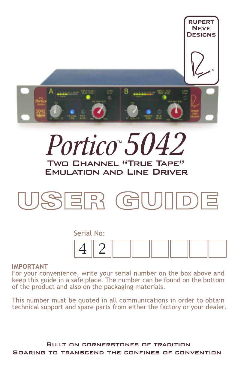

INTRODUCTION
Thank you for your purchase of the 5042 Two Channel "True Tape" Emulation/Line Amp unit.
Everyone at Rupert Neve Designs hope you enjoy using this tool as much as we have enjoyed
designing and building it. Please take note of the following list of safety concerns and power
requirements before the use of this or any Portico Series
Safety
It’s usual to provide a list of “do’s and dont’s” under this heading but mostly these amount to
common sense issues. However here are some reminders:
The amplifier and processing circuits use genuine “Class A” configurations. “Class A” is not
efficient in terms of power utilization. We have placed sonic quality first in order of importance.
The Portico 5042 dissipates about 8 watts, which means that it will get warm in use. The heat
generated is radiated through the case work and by convection through the ventilation holes.
Therefore the holes should not be covered or blocked. Portico modules may be stacked horizontally
on a desk top or vertically in a rack without heat problems. The anti-slip feet may be removed while
used in a rack, but should be retained for desktop use. Porticos should not be stacked immediately
above or adjacent to other equipment that gets hot. Also bear in mind that other equipment may
radiate strong hum fields which could spoil the performance of your Portico module.
Electronic equipment and liquids are not good friends. If any liquid was spilled such as soda,
coffee, alcoholic or other drink, the sugars and acids will have a very detrimental effect. Sugar
crystals act like little rectifiers and can produce noise, “crackles” etc. SWITCH OFF
IMMEDIATELY because once current starts to flow the mixture hardens, can get very hot (burnt
toffee!) and cause permanent and costly damage. Please contact support as soon as possible at
support@rupertneve.com for resolution.
TM
product.
Don’t operate a Portico in the rain! If it gets wet and you suspect that good clean water may have
got in, Immediately unplug the unit, and remove it from the source of water. Take the cover and
knobs off by removing the 2 back-most screws on both sides only. The cover and front panel will
now slide forward and free of the unit. Gently wipe off any water that’s visible with a soft cloth.
Water may have percolated under the PCB and be hidden between the bottom cover and the PCB.
Use a hair drier to blow and dry out any residual moisture. leave the unit for a few hours to
completely dry out. If the moisture was due to CLEAN water, your Portico should be up and
running without any further problem.
Rear connecting cables can get very untidy when a number of Portico modules are stacked on
your bench. It’s a good idea to use cable ties to bunch the cords into a tidy form.
Don’t be tempted to operate a Portico with the cover removed. The cover provides magnetic
screening from hum and R.F. stray fields.
1

POWER REQUIREMENTS
Each Portico 5042 module has a built in DC to DC converter that provide +/– 17.5 VDC for the
amplifiers. The input is protected from reverse polarity, and must be center pin positive. The
converters will work from any DC supply from 9 to 18 volts that is reasonably “clean”. Avoid using
a Power Outlet on the same circuit as air conditioning or other equipment that regularly switches on
and off. Unplug the Portico power unit(s) during a thunder storm or if it will be unused for a long
period.
The power consumed over the 9 to 18 volt range is almost constant; the current varies with
available voltage as follows:-
@ 9VDC Current is 0.93A typical: Power = 8.4 watts
@ 12VDC Current is 0.68 A typical: Power = 8.16watts
@ 15VDC Current is 540 mA typical: Power = 8.1 watts
@ 18VDC Current is 450 mA typical: Power = 8.1 watts
An external, robust and reliable high quality mains power unit, similar to the type used with the
better quality laptop computers is supplied. This power unit converts your A.C. mains voltage,
typically anything from 100 to 240 Volts depending on where you live, to the required low voltage
D.C. (9 to 18 Volts). You will encounter many types of mains power wall sockets in different
countries. One of the advantages of this method of feeding equipment is that external power units
will work from almost any of the very wide range of mains supply voltages and frequencies that are
found world-wide.
Portico™ 5042 module power units leave the factory with standard U.S. plugs. Any good quality
connecting cord may be substituted.
Several sizes of power units available for use when feeding two, eight or more Portico™ 5042
modules together, depending upon the configuration that has been ordered. There are no special
requirements for these Portico™ low voltage power units other than that they must be of good
quality, reliable and able to supply enough current for the number of Portico™ modules in use. The
power unit(s) supplied with your Portico™ meets these requirements.
2

FEATURE LIST
5042 Two Channel "True Tape" Emulation/Line Amp
Front Panel
Level Meter Reads
a) Input level from
0 to +22dBu
b) Signal level being
sent to tape
ENGAGE
TAPE
INPUT LEVEL
TAPE LEVEL
TO A
BUSS
The
Portico
Series
5042
LINE AMP
TAPE FX
A
-
12
0 22dB2 4 10 186 14
0
dB
+
TRIM
LINE-UP
12
Inserts "tape circuit" when pressed or
high quality line amplifier when depressed
Trim
Control provides +/-12dB
adjustment to compensate for incoming
signal levels prior to the tape circuit
5042 Two Channel "True Tape" Emulation/Line Amp
Power Switch
Disconnects supply
from internal power converters
7.5 / 15 IPS
Selects
emphasis/de-emphasis
record/replay
Tape characteristics
7.5
IPS
15
IPS
SATURATION
MIN MAX
Engage Tape
Back Panel
Selects the meter to read
between input level
or tape magetization level
0 22dB2 4 10 186 14
B
LINE-UP
0
dB
ENGAGE
+
12
-
12
TRIM
TAPE
Sends signal
To Buss output
Controls the signal level being sent
Meter Selector
7.5
INPUT LEVEL
TAPE LEVEL
TO B
BUSS
SATURATION
MIN
IPS
15
IPS
RUPERT
NEVE
DESIGNS
MAX
To Buss
Saturation Level
to the magnetic "tape head"
Input
Transformer-coupled
balanced and floating
1 = GND 2 = HOT 3 = COLD
LINE AMP
5042
TAPE FX
+
12VDC
POWER
DC input jack
2.1 x 5.5 x 9.5mm
Center Positive
TM
Portico
Bussing System
Connect as many units together as you'd
like to create your own mixes using
optional bussing modules
Top and bottom rows are normalled
together to allow for an IN / OUT / THRU
configuration
B
OUTPUT OUTPUT
INPUT
Output
Transformer coupled
Balanced and floating
1 = GND 2 = HOT 3 = COLD
3
A
INPUTA BUSS B BUSS

PRIMARY FEATURES
The Portico™ 5042 consists of two identical Line Driving amplifiers having transformer balanced
inputs and outputs. The sonic quality of these amplifiers is such that, by providing galvanic
isolation, simple single-sided circuit topology, and freedom from grounding problems they are
capable of enhancing the sonic quality of many signal sources, especially those of digital origin.
The sonic “Signature” is one of extreme purity and the image is consistent with that of Rupert
Neve’s original designs of 35 – 40 years ago. More detailed discussion on the sonic image and the
way in which an analog designer’s approach can sweeten and “warm” some of the cold, storage and
editing processes, may be found on rupertneve.com.
Control Functions
TRIM control provides +/– 12dB adjustment of gain to compensate for incoming signal levels prior
to feeding the TAPE circuit
ENGAGE TAPE push button inserts the “Tape” circuit when pressed (illuminated).
The Meter push button switch selects the meter to read INPUT LEVEL or TAPE SATURATION
LEVEL
INPUT LEVEL reads the balanced signal level at the input of the Portico™ 5042.
TAPE LEVEL reads the signal level being sent to the simulated Tape Head. (Equivalent to
Record Level in a real Tape Recorder)
LINE UP The incoming signal level should be set by adjustment of the “TRIM” control so that this
first LED starts to light (0 dB). When the Meter Selector is set to TAPE LEVEL there is no meter
reading unless ENGAGE TAPE push button is pressed,.
7.5 IPS – 15 IPS Push button selects the emphasis/de-emphasis, Record/Replay Tape characteristic.
SATURATION Controls the signal level being sent to the magnetic Tape Head.
At the same time the gain of the replay amplifier is reduced. As the SATURATION level increases,
the replay gain is reduced so that the overall IN/OUT signal level remains more or less constant. In
a real Tape recorder, you would adjust the Record and Replay gain controls separately. In the
™
Portico
level only varies as the “Tape” saturation level changes. As you approach maximum
SATURATION setting, the output signal level will drop due to the effect of extreme saturation.
The Portico™ 5042 host line amplifier has a much higher output level capability than the “Tape”
circuit embodied within it. The gain of the Record and Replay amplifiers has been adjusted so that
with the TRIM control set to 0 dBu and the ENGAGE TAPE button OUT, an incoming signal of 0
dBu, will cause the first meter LED to illuminate. With the ENGAGE TAPE button pressed and the
SATURATION control at MIN, the same first meter LED will continue to light regardless of
whether the meter Button is IN or OUT, i.e. INPUT LEVEL or TAPE LEVEL. This is the minimum
recommended Record Level. With the meter switched to TAPE LEVEL, rotating the
SATURATION control Clockwise progressively illuminates the LEDs. With the SATURATION
control rotated to MAX, the maximum recommended Record level is achieved. At MAX, with an
incoming 0 dBu signal, the Tape circuit is running just below clipping point
5042 the Record and Replay gain controls are coupled so that the overall IN/OUT signal
4

PRIMARY FEATURES
7.5
IPS
15
IPS
RUPERT
NEVE
DESIGNS
MAX
The
Portico
Series
5042
LINE AMP
TAPE FX
A
-
12
0 22dB2 4 10 186 14
0
dB
+
TRIM
LINE-UP
12
ENGAGE
TAPE
INPUT LEVEL
TAPE LEVEL
TO A
BUSS
SATURATION
MIN MAX
7.5
IPS
15
IPS
0 22dB2 4 10 186 14
B
LINE-UP
0
dB
+
12
-
12
TRIM
ENGAGE
TAPE
INPUT LEVEL
TAPE LEVEL
TO B
BUSS
SATURATION
MIN
If the incoming signal is low, (for example from a consumer Hi-Fi source), it is recommended that
you rotate the TRIM control clockwise to bring the incoming signal up to the point where the first,
or LINE UP LED is just illuminated.
MAIN OUTPUT
The main output signal comes from the output transformer secondary which is balanced and ground
free. A ground free connection ensures virtual freedom from hum and radio frequency interference
due to ground loops. Ideally the output of this module should be fed to a balanced destination such
as the input to another Portico
™
module or one of the many high quality vintage modules still in
current use.
The Main Output may be used with one leg grounded without any change in performance. If the
destination is to unbalanced equipment, do not “ground” one leg at the Portico
™
output. Simply
make connection as you would to a balanced destination. The fact that the destination is
unbalanced means that the connection becomes grounded one side (“cold” or “earth”) by that item
of equipment. No further grounding is needed to avoid ground loops.
Maximum output level of the Portico™ 5042 is +25dBu, which provides a large margin over and
above the likely maximum requirement of any destination equipment to which the Portico
™
5042 is
connected.
BUSS OUTPUT
When the TO A BUSS or TO B BUSS button is engaged, an unbalanced Monitor output signal is
fed to a high impedance Buss output (i.e. through 4,700 ohms). It is intended for use with the
™
Portico
added to the Portico
5014 Stereo Buss Mixer - Monitor module and with similar projected units as they are
™
series.
This Buss Monitor connection is derived at the Line Output of the Portico™ 5042 pre output
transformer. A TRS patch cord is used to connect the Portico™ 5042 Buss output to one of the 5014
inputs. The signal level at the output of the Portico™ 5014 is designed so that it is equal in level to
that at the Portico™ 5042 output.
METER
An eight segment LED bar-graph meter is fitted for each channel, calibrated with two scales
selected by the adjacent Push Button switch:
INPUT LEVEL Calibrated: 0 dB, 2dB, 4dB, 6dB, 10dB, 14dB, 18dB 22dB
TAPE LEVEL Indicates the level being fed to the Tape circuit, or Amount of Tape Saturation.
A Power On/Off switch on the rear panel disconnects the external Power source.
5

THE TAPE SOUND
Tape Recorders were first used by professional recording studios in the late 1940’s, soon after
WW2. They were adapted from the German Magnetofon that had been used by the German Navy
to improve security of communications with their submarines.
It could be claimed that the magnetic tape recorder was the device that really made the modern
Music Recording Industry possible. Before that time recordings were cut on lacquer or wax
master disks. Although the sound quality of the Long Playing record achieved a very high
standard, no editing or “dubbing” was practical.
The tape recording channel consisted of a “Drive” amplifier that fed the magnetic “Record” head
winding through a constant current circuit. A replay amplifier, connected to the “Playback” head,
with suitable equalization, then amplified the very small signals from this “Playback” head to
restore line level. Because of the high impedances and the impossibility of controlling this
dynamic process by, for example using negative feedback, the process was somewhat non-linear,
exhibiting compression at high levels, noise at low levels and considerable 3
at the low frequencies. The frequency response depended on many factors such as the quality of
tape, the head design and, not least, frequent expert maintenance required to optimize the
performance on a daily basis.
In spite of the limitations, “Tape” sound, in the hands of a professional who knew how to get the
best from the medium, was pleasant, enhancing the sound of many instruments and smoothing over
deficiencies in some of the more aggressive sounding microphones.
rd
. harmonic distortion
With these factors in mind, together with nostalgic memories of tape recordings over many years,
we set about reproducing the classic sound of tape!
Because of the non-linearity referred to, tape distortion varies with signal level. When the level is
very high, the signal is compressed and if it is too high it will clip. (which is a highly unpleasant
sound!)
In order to avoid the need for adjustment of both record and playback levels, these two controls
have been ganged so that as the record level is increased, the replay level is decreased.
The tape level meter provides a good reference that, with care, will indicate the approximate
maximum record level of an actual recorder.
You can expect to experience a classic rise in frequency response around 300 Hz and a slight
ringing due to the pre-emphasis at around 12 to 15 kHz., depending on the setting of the 7.5/15
i.p.s. switch. Low frequency Third harmonic distortion is probably the most immediately audible
effect that you will hear. The effect on certain musical instruments is quite incisive, producing the
characteristic coloring of a real tape recorder.
However, tape recorders are actually very good and these effects are not always obvious to the
inexperienced listener. We did not set out to make a “bad” tape recorder!
6

SPECIFICATIONS
Line Amp Specifications
(Measurements with tape circuit disengaged)
Noise:
Measured at Main Output, un-weighted, 400 Hz-22 kHz, Terminated 40 Ohms Balanced.
With Gain at Unity Better than –100 dBu.
Frequency Response:
Measured at +10dBu, trim at unity.
Main Output: @ 10 Hz. –0.50 dB
@ 200 kHz –3 dB
Maximum Output Level:
Balanced and Floating Transformer Output: +25 dBu.
Total Harmonic Distortion and Noise:
@ 1kHz, +20 dBu output level, no load. Better than 0.0015%.
@ 20Hz, +20 dBu output level, no load: 0.250% typical. Mostly 2nd and 3
Harmonic
Crosstalk:
Measured Channel to Channel: Better than –90 dB @ 16kHz
Buss Output:
Output is designed to feed the RND 5014 Buss-mixer, Monitor Amplifier at the internal system
level of –2.5 dBu. Output level of the RND 5014 is then equal to that of the 5042.
rd
Tape FX Specifications
(Measurements with tape circuit engaged)
Maximum Output Level:
Gain trim at Unity, Saturation at Min: +25 dBu
Gain trim at Unity, Saturation at Max: +6 dBu
Noise:
Measured at Main Output, un-weighted, 400Hz-22kHz, input terminated 40 Ohms Balanced.
With Gain at Unity, Saturation control at Min: Better than –70 dBu
With Gain at Unity, Saturation control at Max: Better than –90 dBu
Frequency Response:
Tape engaged, 7.5 IPS -3 dB @ 16 kHz
Tape engaged, 15 IPS -3 dB @ 20 kHz
Low frequency response varies with input gain and saturation settings.
Total Harmonic Distortion and Noise:
Tape Engaged: Approximately 1-2% 2nd and 3
Harmonic below 1 kHz
Crosstalk:
Measured Channel-to-Channel,
Maximum Saturation: Better than –80 dB @ 16kHz
rd
7

BLOCK DIAGRAM
OUT
LINE
OUTPUT
TRANSFORMER
15IPS
7.5IPS
TAPE
ENAGE TAPE
SATURATION
"HEAD"
OUT
BUSS
TO BUSS
METER
TAPE LEVEL
INPUT LEVEL
TRIM
+/-12dB
INPUT
TRANSFORMER
IN
LINE
8
 Loading...