

Brand Logo
reversed out of
black
IB520077ML
INS #
INS #
Installation Instructions – LDA3B*EM* Emergency
Commercial Recessed
Instructions d’installation – Luminaire d’urgence encastré
commercial LDA3B*EM*
Instrucciones de instalación de las luminarias de emergencia
LDA3B*EM* empotradas de uso comercial
WARNING
Risk of Fire, Electrical Shock, Cuts or other Casualty Hazards- Installation and maintenance of this
product must be performed by a qualified electrician. This product must be installed in accordance
with the applicable installation code by a person familiar with the construction and operation of
the product and hazards involved.
Risk of Fire and Electric Shock- Make certain power is OFF before starting installation or
attempting any maintenance. Disconnect power at fuse or circuit breaker.
Risk of Fire- Minimum 90°C supply conductors. For Non-IC fixtures do not install insulation within 3
inches (76 mm) of any part of the luminaire fixture or in a way that may entrap heat.
Risk of Burn- Disconnect power and allow fixture to cool before handling or servicing.
Risk of Personal Injury- Due to sharp edges, handle with care.
Failure to comply with these instructions may result in death, serious bodily injury and property
damage.
DISCLAIMER OF LIABILITY: Cooper Lighting Solutions assumes no liability for damages or losses of any kind
that may arise from the improper, careless, or negligent installation, handling or use of this product.
IMPORTANT: Read carefully before installing fixture. Retain for future reference.
ote:N Do not energize the LED Engine until the protective cover has been removed with the optic and lower trim
properly installed. Do not touch the surface of the LED as it may damage the light engine.
ote:N This fixture should be supported by main runners or other structure that is capable of supporting fixture weight
of 35 Ibs.
SAFETY INSTRUCTIONS
When using electrical equipment, basic safety precautions should always be followed, including the following:
1. This unit is for recessed mounting only. Do not use in hazardous locations nor near gas or electric heaters.
2. Do not use this equipment for other than the intended use.
3. Install only in accordance with National Electrical Code and local regulatory agencies’ requirements.
Installation Instructions – LDA3B*EM* Emergency Commercial Recessed
INSTALLATION
1. To prevent electrical shock and unintentional battery
discharge, do not join the unit connector or install the
EZ Key until the installation is complete. Immediately
prior to permanently turning the A.C. power on,
engage the connector on the battery pack assembly
or insert the EZ Key on the Test Switch Indicator.
SERVICING
1. This fixture provides more than one power supply
output source. To reduce the risk of electrical
shock, disconnect both normal and emergency
sources by turning off the A.C. branch circuit and
by disconnecting the connector on the battery pack
assembly.
2. This unit is for recessed ceiling mounting only. Do not
use outdoors, in hazardous locations, or near gas or
electric heaters.
3. This is a recessed ceiling mounted LED unit with
standby battery operation. In normal mode the LED
will be fully illuminated. In the emergency mode
the LED will provide emergency illumination for a
minimum of 90 minutes in accordance with the UL
924 standard.
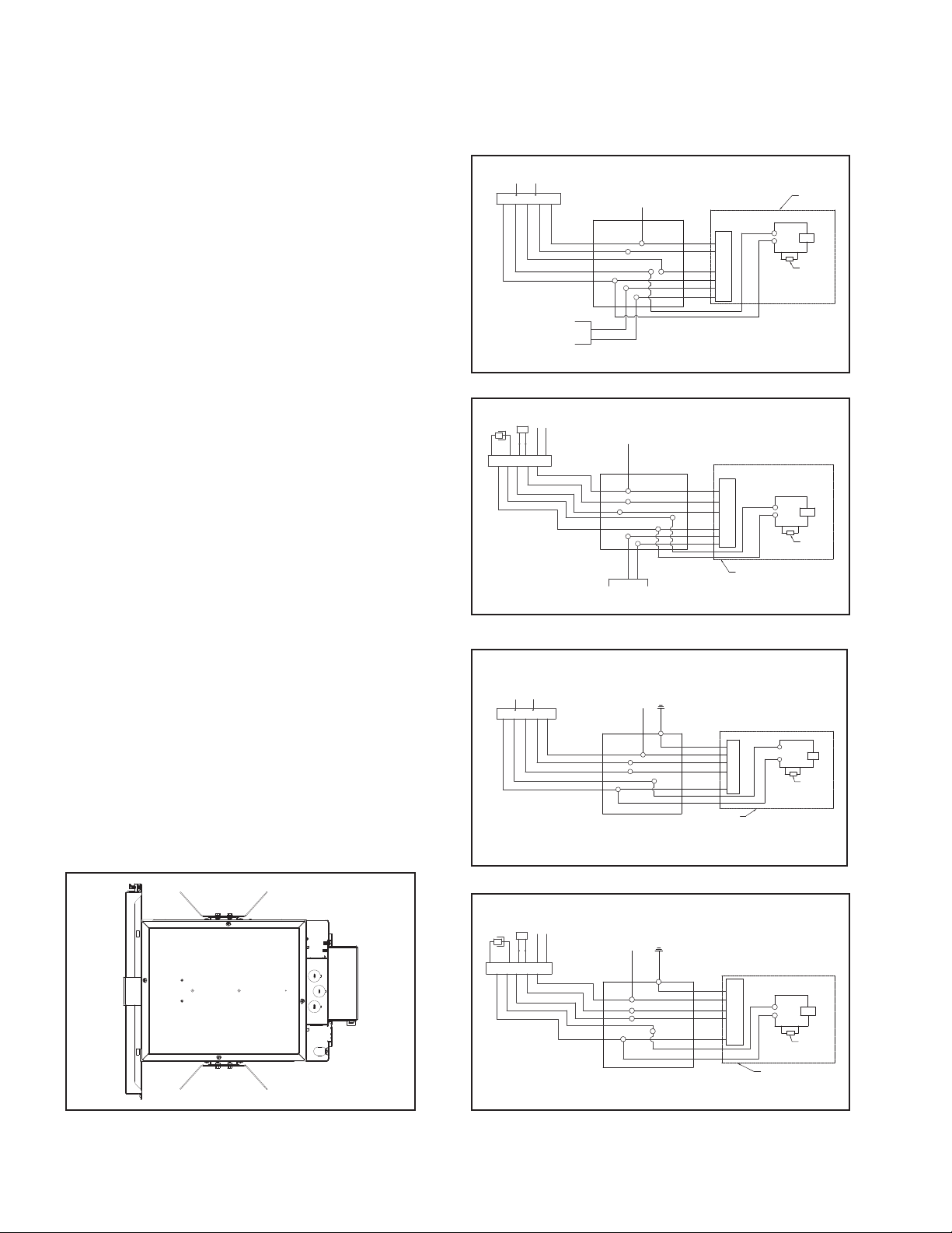
4. The test switch and indicator light may be provided
for ceiling mounting near the fixture in a single gang
switch box (Figure 1).
5. When used in insulated ceilings, insulation must be
kept off of the unit and no closer than 3” from the
unit on all sides.
6. Do not use this equipment for other than the
intended use.
7. Install only in accordance with National Electric Code
and local regulatory agencies requirements.
8. Installation and servicing to be performed only by
qualified personnel.
9. Ceiling access only for maintenance. Battery pack will
not fit thru ceiling.
1. For DE010 EM7-EM14
BLK/OR
(UNSWITCHED HOT)
EM7/EM14
BLUE/WHTIE
RED/WHITE
WHT/BLK
(SWITCHED HOT)
RED
WHITE
WHITE/BLACK
0-10V
DIMMING
FIELD INSTALLED
J-BOX
PURPLE
GREY
2. For DE010 EMBOD
CONVERTER
ITS
VIO
BRN
WHITE
RED
BODINE EM
YELLOW
YELLOW/BLACK
VIO
BRN
BLUE
WHITE/RED
WHITE
WHITE/BLACK
BLACK
J-BOX
For DL2 EM7-EM14
3.
BLK/OR
(UNSWITCHED HOT)
BLUE/WHTIE
EM7/EM14
RED/WHITE
RED
WHT/BLK
(SWITCHED HOT)
WHITE
WHITE/BLACK
J-BOX
WHITE NEUTRAL
GREY
PURPLE
0-10V
DIMMINGFIELD INSTALLED
HOUSING
WHITE NEUTRAL
WHITE
BLACK
RED
DRIVER
BLUE
PURPLE
GREY
WHITE
BLACK
RED
DRIVER
BLUE
PURPLE
GREY
HOUSING
WHITE NEUTRAL
GROUND
GREEN
WHITE
BLACK
RED
DRIVER
BLUE
HOUSING
RED
RED
BLUE
RED
BLUE
+
LED
-
BLACK
TP
NON-IC ONLY
RED
+
LED
-
BLACK
TP
NON-IC ONLY
RED
RED
BLUE
+
LED
-
BLACK
TP
NON-IC ONLY
Figure 1.
2
PORTFOLIO IB520077ML Installation instructions
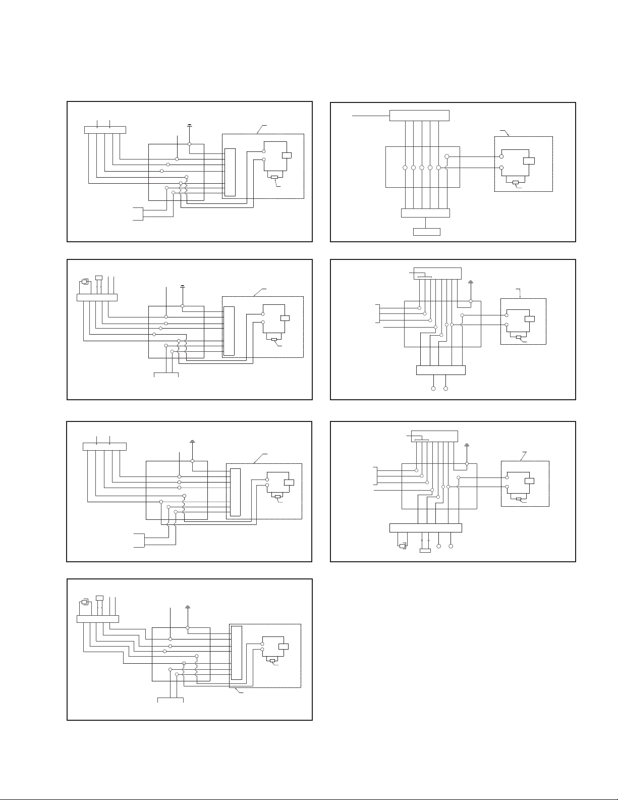
4. For DL2 EMBOD
CONVERTER
ITS
VIO
BRN
WHITE
RED
BODINE EM
YELLOW
YELLOW/BLACK
VIO
BRN
BLUE
BLACK
WHITE/RED
WHITE
WHITE/BLACK
GROUND
WHITE NEUTRAL
J-BOX
GREEN
WHITE
BLACK
RED
BLUE
RED
+
RED
LED
BLUE
HOUSING
BLACK
TP
-
NON-IC ONLY
DRIVER
Installation Instructions – LDA3B*EM* Emergency Commercial Recessed
FIELD INSTALLED
5. For DL5T EM7-EM14
BLK/OR
(UNSWITCHED HOT)
BLUE/WHTIE
EM7/EM14
RED/WHITE
WHT/BLK
(SWITCHED HOT)
RED
WHITE
WHITE/BLACK
DALI CONTROL
FIELD INSTALLED
PURPLE
PURPLE
J-BOX
6. For DL5T EMBOD
CONVERTER
ITS
VIO
BRN
WHITE
RED
BODINE EM
YELLOW
YELLOW/BLACK
VIO
BLUE
BRN
WHITE/BLACK
WHITE/RED
WHITE
BLACK
J-BOX
DALI CONTROL
FIELD INSTALLED
9. For DLV1EM7 - DLV1EM14
FROM DLVP PDM
HOUSING
GROUND
WHITE NEUTRAL
GREEN
WHITE
BLACK
RED
DRIVER
BLUE
PURPLE
PURPLE
RED
RED
BLUE
BLACK
+
LED
-
TP
NON-IC ONLY
J-BOX
POL DRIVER
YELLOW
WHITE
BLACK
YELLOW
WHITE
BLACK
EMERGENCY DRIVER
TEST BUTTON
RED
BLUE
BLUE
RED
RED/WHT
HOUSING
RED
BLUE
RED
BLACK
TP
+
LED
-
NON-IC ONLY
10. For DMX-DMXC5 EM7-EM14
SUPPLIED BY
OTHERS
(CAT5 OPTION
OTHERS
AVAILABLE)
DMX SHIELD
DMX IN-
DMX IN+
WHITE (NEUTRAL)
HOUSING
GROUND
WHITE NEUTRAL
PURPLE
PURPLE
GREEN
WHITE
BLACK
BLUE
PURPLE
PURPLE
RED
DRIVER
RED
RED
+
LED
BLUE
BLACK
-
TP
NON-IC ONLY
ALL DMX WIRE
SUPPLIED BY
(CAT5 OPTION
AVAILABLE)
J-BOX
WHT/BLK
(SWITCHED HOT)
DRIVER
DMX SHIELD
WHT
WHT/BLK
RED
EM7 / EM14
L L
BLUE/WHT
BLK/OR
(UNSWITCHED
NEUTRAL)
GROUND
RED/WHT
GREEN
WHITE
BLUE
BLACK
RED
DMX IN+
DMX IN-
HOUSING
RED
RED
BLUE
BLACK
+
LED
-
TP
NON-IC ONLY
7. For DLE EM7-EM14
BLK/OR
(UNSWITCHED HOT)
EM7/EM14
BLUE/WHTIE
RED/WHITE
WHT/BLK
(SWITCHED HOT)
RED
WHITE
WHITE/BLACK
ECO SYSTEM
DIMMING
8. For DLE EMBOD
CONVERTER
ITS
VIO
BRN
WHITE
RED
VIO
BODINE EM
YELLOW
YELLOW/BLACK
BRN
BLUE
BLACK
WHITE/RED
WHITE
WHITE/BLACK
J-BOX
PURPLE
PURPLE
J-BOX
ECO SYSTEM DIMMING
11. For DMX-DMXC5 EMBOD
SUPPLIED BY
OTHERS
(CAT5 OPTION
GROUND
WHITE NEUTRAL
GREEN
WHITE
BLACK
RED
DRIVER
BLUE
PURPLE
PURPLE
GROUND
WHITE NEUTRAL
PURPLE
PURPLE
0-10V
GREEN
WHITE
BLACK
RED
BLUE
PURPLE
PURPLE
HOUSING
RED
BLACK
+
LED
-
BLACK
TP
NON-IC ONLY
RED
+
LED
-
TP
NON-IC ONLY
RED
BLUE
RED
BLUE
DRIVER
HOUSING
ALL DMX WIRE
SUPPLIED BY
OTHERS
(CAT5 OPTION
AVAILABLE)
AVAILABLE)
DMX SHIELD
DMX IN-
DMX IN+
WHITE (NEUTRAL)
RED
CONVERTER
J-BOX
BODINE EM
WHT
DRIVER
DMX SHIELD
WHT
WHT/BLK
BLUE
BRN
VIO
BRN
VIO
ITS
WHT/
RED
L L
GROUND
YEL
YEL/BLK
BLACK
GREEN
WHITE
BLUE
BLACK
RED
DMX IN+
DMX IN-
HOUSING
RED
RED
BLUE
BLACK
+
LED
-
TP
NON-IC ONLY
PORTFOLIO IB520077ML Installation instructions
3

Installation Instructions – LDA3B*EM* Emergency Commercial Recessed
AVERTISSEMENT
Risque d’incendie, de décharge électrique, de coupure ou d’autres dangers- L’installation et la réparation
de ce produit doivent être faites par un électricien qualifié. Ce produit doit être installé conformément au
code d’installation applicable par une personne qui connaît bien la construction, le fonctionnement du
produit et les dangers encourus.
Risque d’incendie ou de décharge électrique- Assurez-vous que l’alimentation électrique est HORS
TENSION avant de commencer l’installation ou de tenter d’en faire l’entretien. Coupez l’alimentation
électrique au niveau du fusible ou du disjoncteur.
Risque d’incendie- Conducteurs d’alimentation pouvant supporter un minimum de 90°C. Pour les
luminaires qui ne sont pas homologués IC, n’installez pas d’isolant à moins de 76mm (3po) de toute pièce
du luminaire ou de manière à empêcher la dissipation de chaleur.
Risque de brûlure- Débranchez la source d’alimentation et laissez refroidir le luminaire avant de procéder à
son entretien ou à sa manipulation.
Risque de blessure- À cause des bords tranchants, manipulez ce produit avec soin.
La désobéissance aux instructions suivantes représente un risque de blessures graves ou mortelles et de
dommages matériels.
EXONÉRATION DE RESPONSABILITÉ: Cooper Lighting Solutions n’assume aucune responsabilité pour les dommages
ou pertes de toute nature pouvant découler d’une installation inappropriée, imprudente ou négligente et d’une
mauvaise manipulation ou utilisation de ce produit.
IMPORTANT: Lisez attentivement avant d’installer le luminaire. Conservez pour consultation ultérieure.
emarque:R Ne mettez pas le moteur lumineux DEL sous tension tant que le revêtement protecteur n’est pas enlevé et
que la garniture inférieure n’est pas installée correctement. Ne touchez pas à la surface de la DEL pour éviter
d’endommager le moteur lumineux.
emarque:R Ce luminaire doit être supporté par des rails principaux ou une autre structure capable de supporter un luminaire de
15,87 kg (35lb).
Instructions de sécurité
Lorsque vous utilisez un appareil électrique, vous devez toujours respecter les mesures de sécurité de base, y compris les
suivantes:
1. Ce modèle est destiné à un montage encastré seulement. Ne l’utilisez pas dans des endroits dangereux ou à proximité
d’éléments chauffants électriques ou à gaz.
2. N’utilisez pas cet équipement à d’autres fins que celles prévues.
3. Installez l’appareil conformément aux exigences du Code national de l’électricité et des organismes de réglementation
locaux.
4
PORTFOLIO IB520077ML Installation instructions

Instructions d’installation – Éclairage de secours encastré commercia LDA3B*EM*
CHAMP INSTALLÉ
INSTALLATION
1. Pour éviter l’électrocution et l’épuisement accidentel
de la pile, ne raccordez pas le connecteur ou n’installez
pas la clé EZ tant que l’installation n’est pas terminée.
Immédiatement avant de mettre le courant alternatif
définitivement sous tension, insérez le connecteur dans
l’assemblage du bloc-pile ou insérez la clé EZ dans
l’indicateur de l’interrupteur d’essai.
MISE EN SERVICE
1. Ce luminaire offre plusieurs sorties pour l’alimentation
électrique. Pour éviter l’électrocution, débranchez les
sources normales et de secours en mettant le courant
alternatif du circuit de dérivation hors tension en
débranchant le connecteur de l’assemblage du bloc-pile.
2. Ce luminaire n’est dédié qu’à un montage au plafond
seulement. Ne l’utilisez pas à l’extérieur, dans des
endroits dangereux ou près des appareils chauffants à
gaz ou électriques.
3. Ceci est un appareil DEL à montage encastré pour
plafond fonctionnant avec une batterie de réserve. En
mode normal, la DEL sera complètement allumée. En
mode de secours, la DEL offrira un éclairage de secours
pendant au moins 90minutes conformément à la norme
UL924.
4. L’interrupteur d’essai et le témoin lumineux peuvent être
fournis pour un montage au plafond près du luminaire
dans une boite de distribution simple (Figure1).
5. Lorsque utilisé dans des plafonds isolés, l’isolation doit
être maintenue à l’extérieur de l’appareil et à plus de
7,6cm (3po) de tous les côtés de l’appareil.
6. N’utilisez pas cet équipement à d’autres fins que celles
prévues.Install only in accordance with National Electric
Code and local regulatory agencies requirements.
7. Installez seulement conformément aux exigences du
Code national de l’électricité et des organismes de
réglementation locaux.
8. L’installation et la réparation ne peuvent être effectuées
que par une personne qualifiée.
9. Accès au plafond uniquement pour l’entretien. Le blocpile ne peut être installé dans le plafond.
1. For DE010 EM7-EM14
NOIR/ORANGE
(CHAUD NON COMMUTÉ)
BLEU/BLANC
EM7/EM14
ROUGE
ROUGE/BLANC
BLANC/NOIR
(CHAUD COMMUTÉ)
BLANC
BLANC/NOIR
GRADATION 0-10V
CHAMP INSTALLÉ
VIOLET
GRIS
BOITE DE
JONCTION
2. For DE010 EMBOD
CONVERTISSEUR
ITS
VIO
BRN
BLANC
ROUGE
BODINE EM
JAUNE
JAUNE/NOIR
NOIR
VIO
BLANC/ROUGE
BRN
BLANC
BLANC/NOIR
BLEU
BOITE DE
JONCTION
For DL2 EM7-EM14
3.
NOIR/ORANGE
(CHAUD NON COMMUTÉ)
4. For DL2 EMBOD
BLEU/BLANC
EM7/EM14
ROUGE
ROUGE/BLANC
BLANC/NOIR
(CHAUD COMMUTÉ)
BLANC/NOIR
BLANC
BLANC NEUTRE
VIOLET
GRADATION 0-10V
BOITE DE JONCTION
BOITIER
BLANC NEUTRE
BLANC
NOIR
ROUGE
PILOTE
BLEU
VIOLET
GRIS
BLANC
NOIR
ROUGE
PILOTE
BLEU
VIOLET
GRIS
GRIS
FIL DE TERRE
BLANC NEUTRE
BOITIER
VERT
BLANC
NOIR
ROUGE
PILOTE
BLEU
BOITIER
ROUGE
ROUGE
+
LED
BLEU
ROUGE
BLEU
ROUGE
-
NOIR
TP
NON-IC
UNIQAUEMENT
ROUGE
+
LED
-
NOIR
TP
NON-IC
UNIQAUEMENT
ROUGE
+
LED
BLEU
-
NOIR
TP
NON-IC
UNIQAUEMENT
Figure 1.
CONVERTISSEUR
ITS
VIO
BRN
BLANC
ROUGE
BODINE EM
JAUNE
JAUNE/NOIR
NOIR
VIO
BLANC/ROUGE
BLEU
BRN
BLANC
BLANC/NOIR
BOITE DE JONCTION
FIL DE TERRE
BLANC NEUTRE
VERT
BLANC
NOIR
ROUGE
BLEU
PORTFOLIO IB520077ML Installation instructions
ROUGE
BLEU
BOITIER
NOIR
TP
+
LED
-
NON-IC
UNIQAUEMENT
ROUGE
PILOTE
5

Instructions d’installation – Éclairage de secours encastré commercia LDA3B*EM*
5. For DL5T EM7-EM14
NOIR/ORANGE
(CHAUD NON COMMUTÉ)
EM7/EM14
BLEU/BLANC
ROUGE
ROUGE/BLANC
BLANC/NOIR
(CHAUD COMMUTÉ)
BLANC
BLANC/NOIR
DALI CONTROL
CHAMP INSTALLÉ
VIOLET
VIOLET
6. For DL5T EMBOD
CONVERTISSEUR
ITS
VIO
BRN
BLANC
ROUGE
BODINE EM
JAUNE
JAUNE/NOIR
NOIR
VIO
BLANC/ROUGE
BRN
BLANC
BLANC/NOIR
BLEU
BOITE DE
JONCTION
BOITE DE
JONCTION
DALI CONTROL
CHAMP INSTALLÉ
9. For DLV1EM7 - DLV1EM14
DE DLVP PDM
BOITIER
FIL DE TERRE
BLANC NEUTRE
VERT
BLANC
NOIR
ROUGE
PILOTE
BLEU
VIOLET
VIOLET
ROUGE
ROUGE
+
LED
BLEU
-
NOIR
TP
NON-IC
UNIQAUEMENT
BOITE DE
JONCTION
POL PILOTE
JAUNE
BLANC
NOIR
JAUNE
BLANC
NOIR
PILOTE D'URGENCE
BOUTON TEST
ROUGE
BLEU
BOITIER
ROUGE
NOIR
TP
+
LED
-
NON-IC
UNIQAUEMENT
ROUGE
BLEU
BLEU
ROUGE
ROUGE/BLANC
10. For DMX-DMXC5 EM7-EM14
FOURNI PAR
D'AUTRES
(OPTION CAT5
BOITIER
FIL DE TERRE
BLANC NEUTRE
VIOLET
VIOLET
VERT
BLANC
NOIR
ROUGE
BLEU
VIOLET
VIOLET
PILOTE
ROUGE
ROUGE
+
LED
BLEU
-
NOIR
TP
NON-IC
UNIQAUEMENT
TOUS LES FILS
DMX FOURNIS
PAR D'AUTRES
(OPTION CAT5
DISPONIBLE)
DISPONIBLE)
DMX SHIELD
DMX DANS -
DMX DANS +
BLANC NEUTRE
BOITE DE
JONCTION
BLANC/NOIR
(CHAUD COMMUTÉ)
PILOTE
ROUGE
BLEU
BOITIER
ROUGE
NOIR
+
LED
-
TP
NON-IC
UNIQAUEMENT
DMX SHIELD
BLANC
BLANC/NOIR
ROUGE
EM7 / EM14
L L
FIL DE TERRE
ROUGE/BLANC
BLEU/BLANC
NOIR/ORANGE
(NEUTRE NON COMMUTÉ)
VERT
BLANC
BLEU
NOIR
ROUGE
DMX DANS +
DMX DANS -
7. For DLE EM7-EM14
NOIR/ORANGE
(CHAUD NON COMMUTÉ)
EM7/EM14
BLEU/BLANC
BLANC/NOIR
(CHAUD COMMUTÉ)
ROUGE
ROUGE/BLANC
BLANC
BLANC/NOIR
ATTÉNUATION
ECO SYSTEM
8. For DLE EMBOD
CONVERTISSEUR
ITS
VIO
BRN
BLANC
ROUGE
BODINE EM
JAUNE
JAUNE/NOIR
NOIR
VIO
BLANC/ROUGE
BRN
BLANC
BLANC/NOIR
BLEU
BOITE DE
JONCTION
VIOLET
VIOLET
BOITE DE
JONCTION
BLANC NEUTRE
VIOLET
GRADATION 0-10V
ECO SYSTEM
CHAMP INSTALLÉ
11. For DMX-DMXC5 EMBOD
FOURNI PAR
D'AUTRES
(OPTION CAT5
FIL DE TERRE
BLANC NEUTRE
VERT
BLANC
NOIR
ROUGE
PILOTE
BLEU
VIOLET
VIOLET
FIL DE TERRE
VERT
BLANC
NOIR
ROUGE
BLEU
VIOLET
VIOLET
VIOLET
BOITIER
ROUGE
NOIR
ROUGE
TP
NOIR
TP
LED
NON-IC
UNIQAUEMENT
+
LED
-
NON-IC
UNIQAUEMENT
+
-
ROUGE
BLEU
ROUGE
BLEU
PILOTE
BOITIER
TOUS LES FILS
DMX FOURNIS
PAR D'AUTRES
(OPTION CAT5
DISPONIBLE)
DISPONIBLE)
DMX SHIELD
DMX DANS -
DMX DANS +
BLANC NEUTRE
ROUGE
CONVERTISSEUR
BOITE DE
JONCTION
BLANC
DMX SHIELD
BLANC
BODINE EM
PILOTE
ROUGE
BLEU
BOITIER
ROUGE
NOIR
+
LED
-
NON-IC
TP
UNIQAUEMENT
DMX DANS -
BLANC/NOIR
BLEU
BRN
VIO
BRN
VIO
ITS
BLANC/
ROUGE
L L
FIL DE TERRE
JAUNE
JAUNE/NOIR
NOIR
VERT
BLANC
BLEU
NOIR
ROUGE
DMX DANS +
6
PORTFOLIO IB520077ML Installation instructions

Instrucciones de instalación: luminarias de emergencia LDA3B*EM* empotradas de uso comercial
ADVERTENCIA
Riesgo de incendio, descarga eléctrica, cortes u otros riesgos de accidentes: La instalación y el mantenimiento
de este producto deben ser realizados por un electricista calificado. Este producto debe ser instalado de
acuerdo con el código de instalación correspondiente por una persona familiarizada con la construcción y
operación del producto y los riesgos involucrados.
Riesgo de incendio/descarga eléctrica: Asegúrese de que la alimentación esté APAGADA antes de comenzar
la instalación o intentar cualquier mantenimiento. Desconecte el suministro eléctrico desde el fusible o el
disyuntor.
Riesgo de incendio: Conductores de suministro mínimo de 90°C. Para luminarias sin IC no instale
aislamiento dentro de 3 pulgadas (76 mm) de cualquier parte de la luminaria o de una manera que pueda
atrapar el calor.
Riesgo de quemaduras: desconecte la alimentación y espere que la luminaria se enfríe antes de manipularla o
repararla.
Riesgo de lesiones personales: Debido a los bordes filosos, manipúlelo con cuidado.
El incumplimiento de estas instrucciones puede ocasionar la muerte, lesiones corporales graves y daños a
la propiedad.
RENUNCIA DE RESPONSABILIDAD: Cooper Lighting Solutions no asume ninguna responsabilidad por daños o
pérdidas de ningún tipo que puedan surgir por la instalación, manipulación o uso inadecuado, descuidado o
negligente de este producto.
IMPORTANTE: Lea atentamente antes de instalar la luminaria. Conserve estas instrucciones para tenerlas como
referencia futura.
ota:N No energice el motor del LED hasta que la cubierta protectora haya sido removida con la óptica y la moldura inferior
debidamente instalada. No toque la superficie del LED ya que puede dañar el motor de la luz.
ota:N Esta luminaria debe estar sostenida por perfiles principales u otra estructura con capacidad de sostener el peso de una
luminaria de 35 libras.
Instrucciones de seguridad
Cuando utilice equipos eléctricos, siempre debe seguir precauciones de seguridad básicas, incluidas las siguientes:
1. Esta unidad es para montaje empotrado solamente. No la utilice en ubicaciones peligrosas ni cerca de estufas de gas o
eléctricas.
2. No utilice este equipo para otro fin diferente al indicado.
3. Instale únicamente de conformidad con el Código Eléctrico Nacional y los requerimientos de las agencias regulatorias
locales.
PORTFOLIO IB520077ML Installation instructions
7

Instrucciones de instalación: luminarias de emergencia LDA3B*EM* empotradas de uso comercial
INSTALACIÓN
1. Para evitar descargas eléctricas y la descarga involuntaria
de la batería, no una el conector de la unidad ni instale
la llave EZ hasta que la instalación esté completa.
Inmediatamente antes de conectar la alimentación de
CA de manera permanente, enganche el conector a la
unidad del paquete de baterías o inserte la llave EZ en el
indicador del interruptor de prueba.
SERVICIO DE MANTENIMIENTO
1. Esta luminaria incluye más de una fuente de
alimentación de energía de salida. Para disminuir el
riesgo de descarga eléctrica, desconecte tanto la
fuente normal como la de emergencia, mediante la
desactivación del circuito de rama de CA y el conector
de la unidad del paquete de baterías.
2. Esta unidad es solo para montaje empotrado en el techo.
No la utilice en exteriores, en ubicaciones peligrosas ni
cerca de estufas de gas o eléctricas.
3. Esta es una unidad LED de montaje empotrado en el
techo con la posibilidad de funcionamiento a batería de
reserva. En modo normal, la luz LED estará totalmente
iluminada. En modo de emergencia, la luz LED brindará
una iluminación de emergencia por un mínimo de
90minutos, de conformidad con el estándar UL 924.
4. El interruptor de prueba y la luz indicadora pueden
incluirse para el montaje en el techo cerca de la luminaria
en una caja de interruptores de banda única (Figura1).
5. Cuando se usa en techos aislados, el aislamiento debe
mantenerse alejado de la unidad y a menos de 3in
(76.2mm) de la unidad en todos los lados.
6. No utilice este equipo para otro fin diferente al indicado.
7. Instale únicamente de conformidad con el Código
Eléctrico Nacional y los requisitos de las agencias
regulatorias locales.
8. Solo personal cualificado debe realizar la instalación y
prestar servicio de mantenimiento.
9. Acceso al techo solo para mantenimiento. El paquete de
baterías no calza a través del techo.
1. For DE010 EM7-EM14
NEGRO/NARANJA
(SIN CONMUTAR CALIENTE)
EM7/EM14
ROJO/BLANCO
AZUL/BLANCO
BLANCO/NEGRO
(ENCENDIDO CALIENTE)
BLANCO/NEGRO
ROJO
BLANCO
DIMMING 0-10V
CAMPO INSTALADO
CAJA DE CONEXIONES
VIOLETA
GRIS
2. For DE010 EMBOD
CONVERTIDOR
ITS
VIO
BRN
BLANCO
ROJO
VIO
BODINE EM
AMARILLO
AMARILLO/NEGRO
BRN
NEGRO
NEGRO
BLANCO/ROJO
BLANCO
BLANCO/NEGRO
For DL2 EM7-EM14
3.
NEGRO/NARANJA
(SIN CONMUTAR CALIENTE)
EM7/EM14
ROJO/BLANCO
AZUL/BLANCO
BLANCO/NEGRO
(ENCENDIDO CALIENTE)
BLANCO/NEGRO
ROJO
BLANCO
CAJA DE CONEXIONES
NEUTRO BLANCO
VIOLETA
DIMMING 0-10V
CAMPO INSTALADO
NEUTRO BLANCO
CAJA DE CONEXIONES
GRIS
NEUTRO BLANCO
CABLE DE
TIERRA
BLANCO
NEGRO
ROJO
AZUL
VIOLETA
GRIS
BLANCO
NEGRO
ROJO
AZUL
VIOLETA
GRIS
VERDE
BLANCO
NEGRO
ROJO
AZUL
CAJA
ROJO
ROJO
AZUL
CONDUCTOR
ROJO
AZUL
CONDUCTOR
CAJA
CONDUCTOR
CAJA
+
LED
-
NEGRO
TP
SOLO SIN IC
ROJO
+
LED
-
NEGRO
TP
SOLO SIN IC
ROJO
ROJO
+
LED
AZUL
NEGRO
-
TP
SOLO SIN IC
Figure 1.
8
PORTFOLIO IB520077ML Installation instructions
4. For DL2 EMBOD
CONVERTIDOR
ITS
VIO
BRN
BLANCO
ROJO
VIO
BODINE EM
AZUL
AMARILLO
AMARILLO/NEGRO
BLANCO/ROJO
BRN
BLANCO/NEGRO
NEGRO
BLANCO
NEUTRO BLANCO
CAJA DE CONEXIONES
CABLE DE
TIERRA
VERDE
BLANCO
NEGRO
ROJO
AZUL
ROJO
+
ROJO
LED
AZUL
CONDUCTOR
-
NEGRO
TP
SOLO SIN IC
CAJA

Instrucciones de instalación: luminarias de emergencia LDA3B*EM* empotradas de uso comercial
(OPCIÓN CAT5 DISPONIBLE)
(OPCIÓN CAT5 DISPONIBLE)
5. For DL5T EM7-EM14
NEGRO/NARANJA
(SIN CONMUTAR CALIENTE)
EM7/EM14
ROJO/BLANCO
AZUL/BLANCO
BLANCO/NEGRO
(ENCENDIDO CALIENTE)
BLANCO
BLANCO/NEGRO
ROJO
DALI CONTROL
CAMPO INSTALADO
VIOLETA
VIOLETA
6. For DL5T EMBOD
CONVERTIDOR
ITS
VIO
BRN
BLANCO
ROJO
VIO
BODINE EM
AZUL
AMARILLO
AMARILLO/NEGRO
BLANCO/ROJO
BRN
BLANCO/NEGRO
NEGRO
BLANCO
CAJA DE
CONEXIONES
CAJA DE
CONEXIONES
DALI CONTROL
CAMPO INSTALADO
9. For DLV1EM7 - DLV1EM14
CABLEADO DE DLVP PDM
CAJA
CABLE DE
TIERRA
NEUTRO BLANCO
VERDE
BLANCO
NEGRO
ROJO
CONDUCTOR
AZUL
VIOLETA
VIOLETA
ROJO
ROJO
+
LED
AZUL
-
NEGRO
TP
SOLO SIN IC
CAJA DE
CONEXIONES
POL CONDUCTOR
AMARILLO
BLANCO
NEGRO
ROJO
AMARILLO
BLANCO
NEGRO
ROJO
CONDUCTOR DE EMERGENCIA
BOTÓN DE PRUEBA
ROJO
AZUL
CAJA
ROJO
NEGRO
TP
+
LED
-
SOLO SIN IC
AZUL
AZUL
ROJO/BLANCO
10. For DMX-DMXC5 EM7-EM14
SUMINISTRADO POR OTROS
(OPCIÓN CAT5 DISPONIBLE)
CAJA
CABLE DE
TIERRA
NEUTRO BLANCO
VIOLETA
VIOLETA
VERDE
BLANCO
NEGRO
AZUL
VIOLETA
VIOLETA
ROJO
CONDUCTOR
ROJO
ROJO
+
LED
AZUL
NEGRO
-
TP
SOLO SIN IC
SUMINISTRADOS POR OTROS
ALAMBRES DMX
TODOS LOS
DMX SHIELD
DMX IN-
DMX IN+
NEUTRO BLANCO
DMX IN-
DMX SHIELD
BLANCO
BLANCO/NEGRO
(ENCENDIDO CALIENTE)
CONDUCTOR
BLANCO
DMX IN+
BLANCO/NEGRO
EM7 / EM14
L L
AZUL
NEGRO
ROJO
AZUL/BLANCO
ROJO
(NEUTRO NO CONMUTADO)
VERDE
CAJA DE
CONEXIONES
ROJO/BLANCO
NEGRO/NARANJA
CABLE DE
TIERRA
CAJA
ROJO
ROJO
AZUL
NEGRO
+
LED
-
TP
SOLO SIN IC
7. For DLE EM7-EM14
NEGRO/NARANJA
(SIN CONMUTAR CALIENTE)
EM7/EM14
ROJO/BLANCO
AZUL/BLANCO
BLANCO/NEGRO
(ENCENDIDO CALIENTE)
BLANCO
BLANCO/NEGRO
ROJO
DIMMING PARA
SISTEMA ECO
8. For DLE EMBOD
CONVERTIDOR
ITS
VIO
BRN
BLANCO
ROJO
VIO
BODINE EM
AZUL
AMARILLO
AMARILLO/NEGRO
BRN
BLANCO/NEGRO
NEGRO
BLANCO/ROJO
BLANCO
CAJA DE
CONEXIONES
VIOLETA
VIOLETA
CAJA DE
CONEXIONES
DIMMING ECO
SYSTEM 0-10V
CAMPO INSTALADO
11. For DMX-DMXC5 EMBOD
SUMINISTRADO POR OTROS
(OPCIÓN CAT5 DISPONIBLE)
CABLE DE
TIERRA
NEUTRO BLANCO
VERDE
BLANCO
NEGRO
ROJO
CONDUCTOR
AZUL
VIOLETA
VIOLETA
CABLE DE
TIERRA
NEUTRO BLANCO
VIOLETA
VIOLETA
VERDE
BLANCO
NEGRO
ROJO
AZUL
VIOLETA
VIOLETA
CONDUCTOR
CAJA
ROJO
ROJO
NEGRO
+
LED
-
NEGRO
TP
SOLO SIN IC
+
LED
-
TP
SOLO SIN IC
ROJO
AZUL
ROJO
AZUL
CAJA
SUMINISTRADOS POR OTROS
ALAMBRES DMX
DMX SHIELD
TODOS LOS
DMX IN-
DMX IN+
NEUTRO BLANCO
ROJO
CONVERTER
BODINE EM
BLANCO
CONDUCTOR
ROJO
NEGRO
CAJA
+
LED
-
TP
SOLO SIN IC
DMX SHIELD
BLANCO
BLANCO/
NEGRO
AZUL
BRN
VIO
BRN
VIO
ITS
BLANCO/
ROJO
L L
CABLE DE
TIERRA
ROJO
AZUL
CAJA DE
CONEXIONES
AMARILLO
AMARILLO/
NEGRO
NEGRO
VERDE
BLANCO
AZUL
NEGRO
ROJO
DMX IN+
DMX IN-
PORTFOLIO IB520077ML Installation instructions
9

Warranties and Limitation of Liability
Cooper Lighting Solutions provides a 5-year limited warranty on this LED lighting product. Refer to the complete warranty
terms & conditions of sale at www.cooperlighting.com/legal.
Garanties et limitation de responsabilité
Cooper Lighting Solutions offre une garantie limitée de 5 ans sur ce produit d’éclairage à DEL. Retrouvez toutes les
modalités de vente et de garantie sur www.cooperlighting.com/legal.
Garantías y Limitación de Responsabilidad
Cooper Lighting Solutions ofrece una garantía limitada de 5 años para este producto de iluminación LED. Consulte los
términos y condiciones completos de venta de la garantía en www.cooperlighting.com/legal.
Cooper Lighting Solutions
1121 Highway 74 South
Peachtree City, GA 30269
P: 770-486-4800
www.cooperlighting.com
Canada Sales
5925 McLaughlin Road
Mississauga, Ontario L5R 1B8
P: 905-501-3000
F: 905-501-3172
© 2020 Cooper Lighting Solutions
All Rights Reserved
Printed in China
Imprimé en Chine
Impreso en China
Publication No. IB520077ML
Cooper Lighting Solutions is a
registered trademark.
All trademarks are property
of their respective owners.
Cooper Lighting Solutions est une
marque de commerce déposée.
Toutes les autres marques de
commerce sont la propriété de leur
propriétaire respectif.
Cooper Lighting Solutions es
una marca comercial registrada.
Todas las marcas comerciales
son propiedad de sus respectivos
propietarios.
Product availability, specifications,
and compliances are subject to
change without notice
La disponibilité du produit, les
spécifications et les conformités
peuvent être modifiées sans préavis
La disponibilidad de productos, las
especificaciones y los cumplimientos
están sujetos a cambio sin previo aviso
 Loading...