

Page 1

Freestanding Gas & Electric Cooker Slide–In Freestanding
Porter & Charles
OPERATION MANUAL
FEC 90
Page 2

1. INSTALLATION …………………………………………… PAGES 4- 6
1.1.Ventilation
1.2.Discharge of fuel gases
1.3.Positioning the cooker
1.4 Dimensions and cut-outs
1.5.Connection to the gas supply: current installation standards
1.6.Connection to the electricity supply
1.7.Converting the gas-supply to the hob burners
1.8.Regulating the minimum output of the hob burners
2. MAINTENANCE …………………………………………….. PAGES 7-8
2.1.Gas supply rubber pipe
2.2.Electricity supply cable
2.3.Access to electrical/gas components
2.4.Replacing the thermostat taps
2.5.Removing and fitting the oven door
2.6.Replacing the light bulb
2.7.Glass cover
3. USING THE COOKER ………………………………………… PAGES 9 - 14
3.1. Using the cooking hob
3.2. Ceramic Hob
3.3. Oven Performance
3.4. Using the grill
3.6. Minute timer
3.7. Electronic programmer
3.8. Cooking hob with glass-plate ( mxg 96 mfpi/v model only)
3.9. Fitting the fat filter to giant multiple-fuction oven (fig. 20).
3.10. Fitting the gas burners to the hob
3.11 Telescopic runners (only for certain models)
4. CLEANING …………………………………………………… PAGES 15 - 16
5. DIAGRAMS ………………………………………………… PAGES 17- 19
6. WARRANTY …………………………………………………. PAGE 29
2
Page 3

WARNINGS AND TIPS
⇒ Information about this model and its features is displayed on the appliance plate.
⇒ This appliance has been designed for domestic use only.
⇒ These instructions are only valid for the country indicated in the identification symbols
on the cover of the instruction handbook and on the appliance.
⇒ All installation, adjustments, gas-conversion and maintenance operations must be
carried out by qualified engineers, in accordance with the enclosed instructions and
current installation standards. The manufacturer accepts no liability for faulty
installation, setting, handling and use of the cooker.
⇒ Before carrying out any maintenance or conversion operations unplug the cooker from
the mains and shut off the gas upstream of the appliance. If any components and/or
accessories need replacing, only original Porter & Charles spare parts must be used.
Only qualified technicians may perform installation and maintenance operations.
⇒ Keep the operation manual near the cooker, so that if can be consulted at any time.
This way, the instructions and tips are close at hand for correct use and optimum
performance.
⇒ Before using the cooker remove the plastic protection from the stainless steel,
aluminium and/or painted parts in order to prevent it melting. The utmost care must be
taken when removing this protection so as to avoid damaging the protected parts.
⇒ When the cooker is in use keep children at a safe distance, as the outside of the cooker
can heat up, and they should be kept away until the cooker has completely cooled
down. Likewise children should not play with or use the cooker controls unsupervised.
⇒ Periodically check that there are no gas leaks in the pipe that connects the cooker to
the gas bottle or the supply line; replace it upon expiry
⇒ When the cooker is not in use, ensure that all the knobs are in the off position;
furthermore, if it is unused for a period of time, shut off the gas bottle valve and the
supply valve, as well as the appliance’s mains electricity supply.
⇒ Keep the burners, covers and flame diffusers clean in order to ensure optimum
operation.
⇒ Before using the oven for the first time, we recommend leaving it on for one hour at the
maximum temperature. Doing so may create smoke and unpleasant smells, which are
caused by the glue in the heat insulation or oiled plates. To get rid of these odours, air
room e.g. opening a window.
⇒ Some models are fitted with an aluminium tray, ideal for baking pastries (180-200°C).
Max. load 3 kg.
⇒ Do not discard packaging, accessories or other parts of the appliance into the
environment. If possible, take them to recycling bins or a recycling plant
3
Page 4

INSTALLATION
This appliance shall be installed in accordance with the regulations in force and only in a well
ventilated space. Read the instructions before installing or using the appliance.
1.1. VENTILATION
The room containing this cooker should have an air supply in accordance with local regulations.
- All rooms require an open window, or equivalent and some rooms will require a
permanent vent as well.
- For room areas up to 5 m
- For room areas between 5 m
- If the room is greater than 5 m
2
an air vent of 100 cm2 is required.
2
and 100 cm2 an air vent of 50 cm2 is required.
2
and has a door that opens directly to the outside, then no
air vent is required.
- If there are other fuel burning appliances in the same room local regulations should be
consulted to determine the air vent requirements.
1.2. DISCHARGE OF FUEL GASES
Cooking appliances must always discharge the flue
gases into special hoods (fig.1-C), which must be
connected to chimneys, flue pipes or have direct
access to the outside. If it is not possible to connect
a hood, an electric fan can be fitted to a window or
a wall (fig.1-E), which must be turned on when the
cooker is on, as long as ventilation standards are
strictly adhered to.
1.3. POSITIONING THE COOKER
a) Built-in cooker: Cookers in this class can be fitted
between two units, unless the side
in contact with the cooker is higher
than the hob. In this case, the unit
must stand at least 5 cm away from
the top of the hob. If the cooker has
a baseboard fitted, a 2cm vent must
be made in the front along the entire
width of the cooker.
b) Free standing cooker: After unpacking the cooker, remove the plastic protection from the
stainless steel, aluminium and/or painted parts to avoid it melting.
The utmost care must be taken when removing this protection so as
not to damage the protected parts. Now the feet can be fitted (fig.4).
They must be fixed to the ends of the slits on the cooker pedestal.
Their height can be adjusted in order to line the cooker up with other
units. Ensure that the cooker is perfectly stable. Fit the burners, the
flame diffusers and the grids into their seats on the hob (see
paragraph 3.9). Some models come with rubber pads that prevent
the steel hob surface from being scratched. Fit them to the central
pan grid made of chrome-plated rod.
N.B. When the burners are alight, there must not be any draughts inside the room in
that they may affect the flame or even blow it out. (PLEASE NOTE: The fixing hook is
not provided as the type will depend on the construction of the wall to w hich it will be
drilled and fitted. The installer should provide the fixing hook).
4
Page 5
1.4 Dimensions and Cut-outs
MODEL
60 cm
24 Inches
90 cm
26 Inches
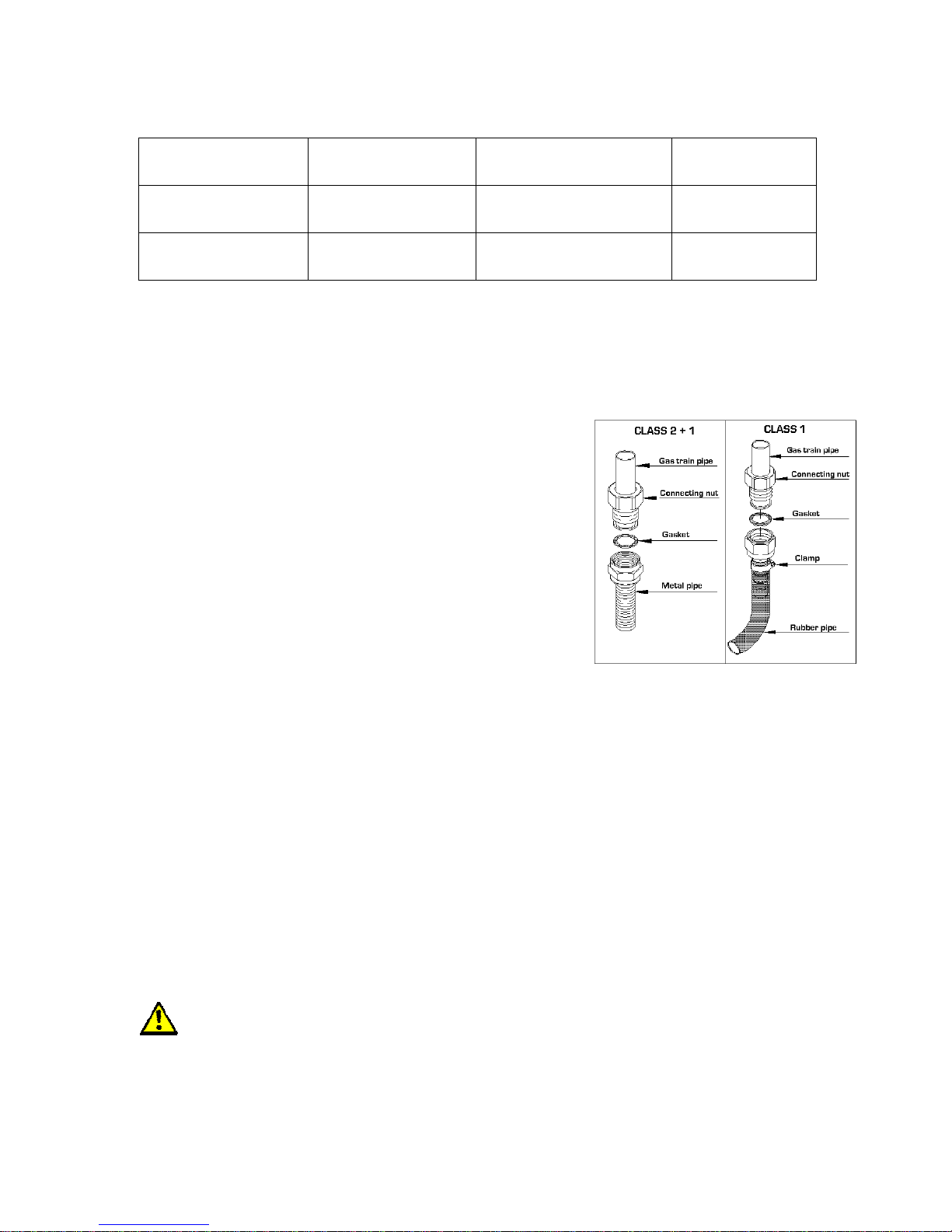
1.5. CONNECTION TO THE GAS SUPPLY: CURRENT INSTALLATION STANDARDS
The cooker should be connected according to local
regulations, using either a rigid or flexible connections.
a) For building in: Use a continuous flexible stainless steel
pipe, as per current installation standards, which can be
extended to a maximum of 2000 mm.; the ends of the pipe
must be fitted with an ISO 228/1coupling and gasket or an
ISO 7/1 threaded coupling with mechanical gasket.
b) For free standing: A non-metallic flexible pipe can be used
as long as it complies with current standards and the
following installation instructions are observed: the pipe
must be longer than 400 mm and shorter than 1500 mm; it
must not exceed 50àC in any point; it is not pulled or
twisted; it cannot be choked and the entire edges, sharp
corners or other similar hazards.
Before connecting the non-metallic flexible pipe, the pipe holder and gasket supplied with the
cooker and/or available form the reseller must be fitted to the pipe/gas train on
the back of the cooker.
c) A certified gas plumber must complete the installation and meet with local regulation
requirements for gas connections. Where the unit has an armour cable a certified electricain
must complete the electrical connection. The white, or neutral wire will not be used and must
be capped using a marrette.
HIEGHT
(Adjustable Feet)
92 cm
36 Inches
92 cm
36 Inches
DEPTH
(Including Rear Vent)
64 cm
25 Inches
64 cm
25 Inches
WIDTH
60 cm
24 Inches
90 cm
35.5 Inches
1.6. CONNECTION TO THE ELECTRICITY SUPPLY
The flexible mains lead is supplied connected to a fused plug fitted with a fuse of 13 amp
capacity. If you need to replace the plug for any reason, it should be carried out as outlined
below:
WARNING: THIS APPLIANCE MUST BE EARTHED.
5
Page 6
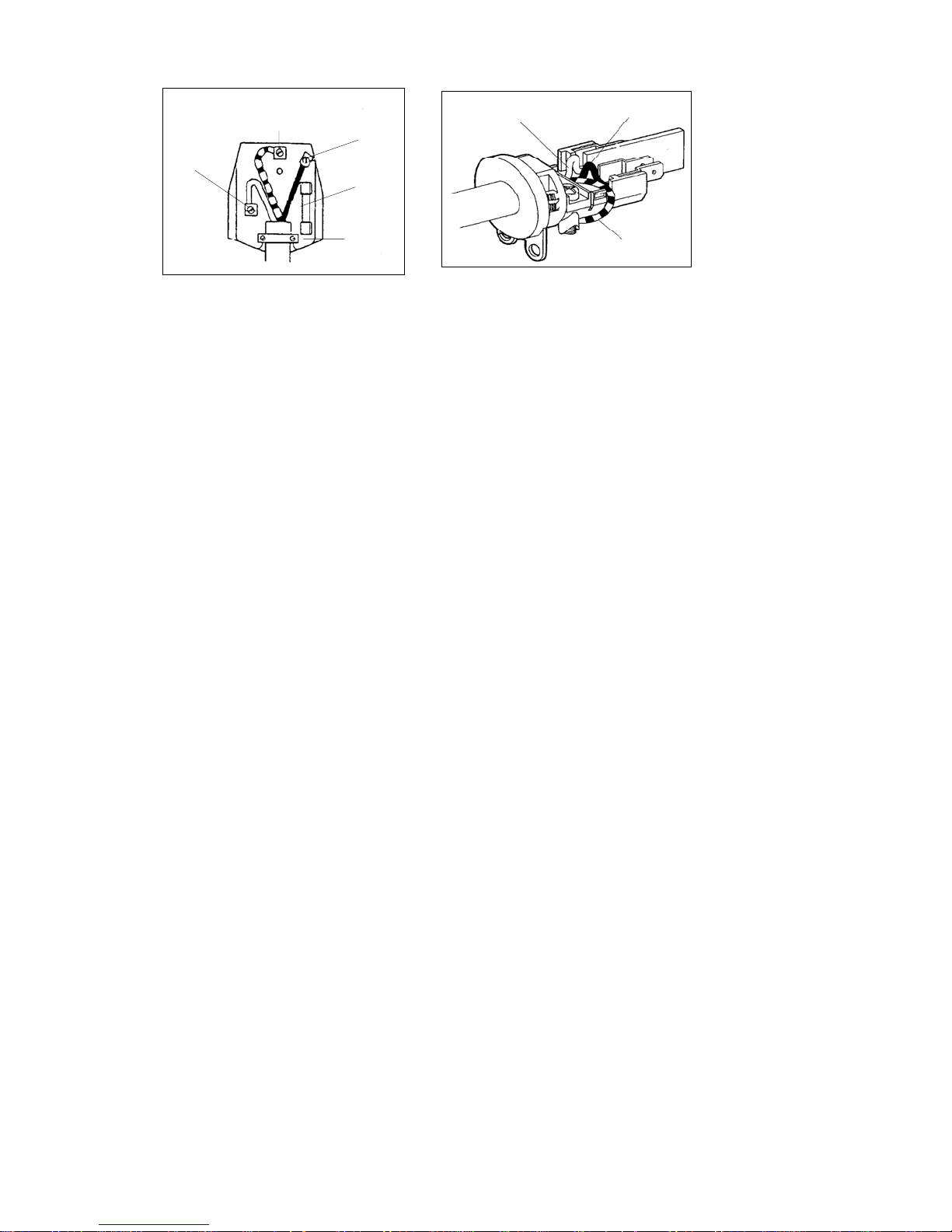
BLACK
TO LINE 1
GREEN
TO EARTH
RED
TO LINE 2
FUSE
BLACK
TO LINE 1
RED
TO LINE 2
CORD
CLAMP
GREEN
TO EARTH
The wires in the mains lead are coloured in accordance with the following code:
Green & Yellow = Earth – Blue= Neutral – Brown= Live
As the colours of the wires in the mains lead of the appliance may not correspond with the
coloured markings, to identify the terminals in your plug, proceed as follows:
1. The wire which is coloured Green & Yellow must be connected to the terminal marked E
(Earth) or coloured Green.
2. The wire which is coloured Blue must be connected to the terminal marked N (Neutral) or
coloured Black.
3. The wire which is coloured Brown must be connected to the terminal marked L (Live) or
coloured Red.
The plug and socket must be accessible after installation. Should the mains lead ever need
replacing it is recommended that this operation is carried out by a qualified electrician who
will replace it with a lead of the same size and temperature rating.
1.7 CONVERTING THE GAS-SUPPLY TO THE HOB BURNERS
Burners: auxiliary, semi-rapid, rapid, triple crown, griddle burner.
These burners are all fitted with injectors designed to create a primary input of air gauged for
each type of gas. This means that the air regulator does not have to be regulated. Proceed as
follows in order to convert from one type of gas to another: remove the grids, covers, holed flame
diffuser and the burner supports (fig. 7); replace the holed injectors as indicated in 7/C according
to the type of gas used (see table 1); put the burner supports, flame diffusers, covers and grids
back in position; regulate the minimum output following the instructions in paragraph 1.7.
1.8 REGULATING THE MINIMUM OUTPUT OF THE HOB BURNERS
Normal/valve taps:
Ignite the burners and turn the knob to the maximum position. Remove the knob and insert a
small flat-head screwdriver into the rod or through the holes on the side of the control panel, in
accordance with the type (fig. 8 A/B). Loosen the by-pass screw by two turns in an anti-clockwise
direction and rotate the rod to the minimum position. Adjust the previously loosened screws until
the flame is lowered but stable, even when rapid changes are made from the maximum to the
minimum position with the burner cold. If safety taps are fitted, let the burner run on minimum for
a few minutes to ensure that the device does not cut in. If it does, increase the minimum.
N.B. For liquid gas settings, the burner minimum must be set by fully tightening the tap
by-passes.
Replace the knob and turn it to the minimum position, remove the knob and adjust the previously
loosened screw until the flame is lowered but stable, even when rapid changes from maximum to
minimum are made and the oven door is opened or closer quickly.
N.B. For liquid gas setting, the oven burner minimum is set by fully tightening the
thermostat by-passes.
6
Page 7

2. MAINTENANCE
WARNINGS:
Before carrying out any maintenance or conversion operations turn off the electricity
supply and close the gas upstream of the appliance. If components and/or
accessories need replacing, use only Porter & Charles spare parts only. All the
operations hereunder must be carried out by qualified technicians in accordance with
the enclosed instructions and current installation standards.
2.1. GAS SUPPLY RUBBER PIPE
The condition of the gas supply pipe should be checked periodically (once a year) and replaced
by the date printed on the outside of the pipe and if there are signs of cracking, cuts, scratches or
burns, or if it is no longer flexible but hard and plastic. The pipe must be suitable for use with
liquid gas and comply with the applicable standards.
2.2. ELECTRICITY SUPPLY CABLE
If the electricity supply cable needs replacing, please remember that this is an X type of
connection; therefore only authorised Porter & Charles technicians may replace it. Use
HO5FRR-F cables only. The earth wire (yellow/green) must be at least 2 cm longer than the other
two phase wires (fig. 5 B). This ensures that the electrics are safe should the wire be pulled
accidentally.
For the cookers with a gas oven and an electric grill, use a 3x1 mm² HO5RR-F cable, for cookers
with electric oven and grill, use a 3x1.5 mm² HO5RR-F cable with a maximum external diameter
of 9 mm.
2.3. ACCESS TO ELECTRICAL/GAS COMPONENTS
To carry out maintenance and/or to replace the electrical components fitted in the back of the
cooker (e.g. light bulb older, rotisserie, supply cable, electric ignition generator, resistors) the rear
protection panel must be removed by unfastening the screws that secure it to the sides.
To carry out maintenance and/or replace the electrical components fitted to the front panel (e.g.
control panel, taps, thermostat, timer, etc), you have to remove the rear panel and also proceed
as follows:
- remove the flue pipe, if fitted;
- remove the hob grids and burners;
- unfasten the screws that secure the cups to the hob and, for models with safety device, also
remove the nuts that secure the thermocouples;
- unscrew the 2 top front or side front screws (fig. 9) that fasten the hob and then lift it;
- remove the knobs and remove the screws that fasten the gas train to the front control panel,
remove the gas train taking care not to damage any pipes or thermocouples.
- to reassemble follow these instructions in reverse order.
2.4. REPLACING THE THERMOSTAT TAPS
If a tap or a thermostat needs replacing, first follow the instructions given in paragraph 2.3.
(access to electrical/gas components), then remove the nut fastens the supply pipe to the burner,
the thermocouple nut and the screws that fasten the tap or the thermostat to the gas train.
Besides the tap or the thermostat, it is also important that the gasket is replaced in order to
prevent any gas leaks. After maintenance, ensure that there are no leaks by using a specific
instrument or soapy water.
7
Page 8

2.5. REMOVING AND FITTING THE OVEN DOOR
Open the oven door fully; insert the rotation-blocking device (A) in the hook on the hinge rods as
illustrated in Fig. 10. Grasp the door on both sides and slowly close until you feel a certain
resistance at this point simultaneously push and lift the door upwards to free it from the cooker
hinge locks and then remove it.
To fit the door, follow these instructions in reverse, taking care that the hinge lock is properly fitted
into the seat.
2.6. REPLACING THE LIGHT BULB
Turn the cooker off at the mains before replacing the bulb.
Open the oven door, remove the protective glass cover, and replace the light bulb (CAUTION: it
must be resistant up to 300°C) and replace the glass protection.
8
Page 9

4. USING THE COOKER
WARNINGS:
- If the burner flames accidentally go out, turn off the KNOB and wait for at least one minute
before igniting.
- Using a gas cooker produces heat and humidity in the room where it is installed. Ensure the
room is well ventilated by keeping all the natural air vents open or by installing an extraction
hood with flue pipe.
- Intensive or extensive use of the cooker may require supplementary ventilation e.g. opening
a window, or more efficient ventilation e.g. increasing the capacity of the mechanic
ventilation, if installed.
If the cooker has an electric oven, there is a green light and also a yellow light, which turns on
and off when the THERMOSTAT cuts in to regulate the oven temperature.
3.1. USING THE GAS COOKING HOB
Automatic electronic ignition built into the knob: turn the knob to the maximum position
push it in and the burner lights up automatically.
• No gas supply (knob turned off)
Maximum gas supply Minimum gas supply
To obtain minimum supply, turn the knob in an anti-clockwise direction until the indicator points to
the small flame
Safety device: once the burner is on, keep the knob pressed for at least 5 seconds and then
release it. The burner remains alight due to the thermocouple (Fig. 7 point A) that keeps the gas
flow by means of a safety valve, which shuts off the gas flow should the burner go out
accidentally.
Burner performance: a variety of pans with a minimum diameter of 120 mm can be used on the
“medium and small” burners. The pans must not have concave or convex bottoms, but be
perfectly flat as shows in Fig. 14. For optimum performance, use the saucepans shown in fig. 13,
i.e. the flames must not go beyond the bottom of the pan. When a liquid starts boiling, lower the
flame as much as possible, but keep it on the boil. For safety reasons, we recommend using pans
with the following diameters on the various burners:
Auxiliary (1000W) 120÷180 mm.
Semi-rapid (1750W) 120÷220 mm.
Rapid (3000W) 180÷280 mm.
Triple Crown (3900W) 240÷330 mm.
Griddle Burner (3000W) 120÷280 mm. (indicated minimum measurements)
Electric plates
The first time the plate is turned on or if it has not been used for a long time, it should be turned
on and left on for 30 minutes in position 1 on the selector switch in order to dry out any humidity
absorbed by the insulating cover. To avoid heat dispersion and damage to the plate, use flat
bottomed pans that have the same diameter as the plate, no more no less (fig. 14). Dry the
bottom of the pan before putting it on the plate. When the plate is on, never stand an empty pan
on it, or leave the plate on without a pan. Turning the plates on – centre the pan on the plate and
turn the corresponding knob to the required position (see Table 2). The increasing numbers
indicate greater power.
.
9
Page 10

3.2 GLASS CERAMIC HOB
60cm HOB
1.2
kW
HL
2.2/0.75
Kw
1.7
kW
90cm Hob
HL
2.4/1.5
kW
2.4/1.5
kW
2.0/1.1
kW
1.7
kW
HL
2.2/0.75
kW
The hi-lite elements make it possible to reach maximum power in a few seconds. Further the
thick fibreglass insulation around the elements prevents heat dispersion and concentrates the
effect.
The energy regulator is a device which regulates power gradually according to the position set
on the knob (% of maximum power). Control of the heating zones is automatic, by activating or
disabling the heating elements at regular intervals, thus ensuring precise, uniform heating ie:
short heating periods and long pauses indicate low temperature; long heating periods and brief
pauses indicate a higher temperature. With the energy regulator, you can totally or partially heat
a particularly zone of the glass ceramic top.
Plate lay-out (see tables)
1.2
kW
10
Page 11

Characteristics of the heating zones in 4 heating plate kitchen ranges.
Position
Front left
Rear left Switch
Front right Switch
Rear right
Type of
command
Energy
regulator
Energy
regulator
Effective heated
zone
All Clockwise 2200W
Central
All
All
All Clockwise 2400W
Circular
Knob
rotation
anticlockwise
anticlockwise
anticlockwise
anticlockwise
max
power
750W
1200W 150 W 200 W 350 W 500 W 850 W 1200 W
1700W 180 W 300 W 450 W 750 W 1200 W 1700 W
1500W
Knob position and relevant power
1 2 3 4 5 6
10 % 25 % 50 % 65 % 90 % 100 %
10 % 25 % 50 % 65 % 90 % 100 %
Characteristics of the heating zones in 5 heating plate ceramic hob.
Position
Front left
Front right Switch
Rear right Switch
Rear left
Type of
command
Energy
regulator
Energy
regulator
Effective heated
zone
All
Central
All
All
All Clockwise 2400W
Circular
Knob
rotation
Clockwise 2200W
anti-
clockwise
anti-
clockwise
anti-
clockwise
anticlockwise
Max
power
7500W
1200W 150 W 200 W 350 W 500 W 850 W 1200 W
1700W 180 W 300 W 450 W 750 W 1200 W 1700 W
1500W
Knob position and relevant power
1 2 3 4 5 6
10 % 25 % 50 % 65 % 90 % 100 %
10 % 25 % 50 % 65 % 90 % 100 %
Central
All Clockwise 2000W
Energy
regulator
Circular
anticlockwise
1100W
10 % 25 % 50 % 65 % 90 % 100 %
Residual heat
The glass ceramic top is divided into 5 heating zones. To ensure extra safety, it has indicator
lights (residual heat indicators), which light up when a zone is hot.
The indicators stay lighted for as long as the heated zone remains hot, even with the plates OFF.
How to use the glass ceramic top
When using the top for the first time, we advise you to turn ON the heating zones one at a time
for a few minutes, in order to eliminate any humidity accumulated in the insulation.
To avoid heat dispersion and for excellent performance, we advise you to use pots/pans with a
flat, thick bottom. Further, whenever possible, the pots should be of the size as the heating zone
being used.
The heated zone stays hot for a certain period of time. You should therefore exploit this by
switching the plate off a few minutes before end of cooking, so that you finish cooking by
exploiting the residual heat accumulated by the glass, and save on energy.
11
Page 12

We advise you to clean when the glass has cooled. Wash the glass with the type of liquid
detergent as per supplied sample, or with soapy water. For stubborn dirt, use the supplied
scraper. Do not use abrasive material such as Scotch brite, metal sponges or the like. Take
care not to spill sugar while cooking, because impossible to remove deposits could be formed.
Any cast-iron pots or with a rough bottom tend to leave light coloured traces, which can be
removed with a cloth dampened with vinegar.
WARNING:
When the top is in operation or the residual heat indicator is ON, take great care,
and keep children away.
WARNING:
If the glass ceramic breaks, disconnect electric power and call in the Lofra
Authorised Service Centre.
3.3. OVEN PERFORMANCE
Electric ovens
STATIC OVENS: heat produced inside the oven by electric elements fitted in the top and bottom
of the oven; these elements can work together or independently. This gives more even cooking,
for example when the cooking time is almost up, the food may need more heat at the top or the
bottom. The temperature is kept constant by the thermostat, which can be set between 50°C and
250°C. During cooking, only open the oven door when strictly necessary. During this cooking
method, humidity loss from the food is slow and uniform.
FAN OVENS; heat is produced by the forced circulation of hot air inside the oven. A circular
element next to a motorised fan heats the air, which this fan circulates evenly and rapidly. This
type of oven cooks faster than traditional ovens; hence you should set your cooking temperatures
10-20°C lower than normal. Once again the thermostat maintains the oven at the pre-selected
temperature, which range from 50°C and 250°C. The oven can take several dishes together
without altering the flavours in any way.
Switching on the multiple-function oven: turn the oven knob marked by the
symbol to the right and set the required temperature, in accordance with the cooking method.
12
or the
Page 13

3.3. OVEN PERFORMANCE
Electric ovens
STATIC OVENS: heat produced inside the oven by electric elements fitted in the top and bottom
of the oven; these elements can work together or independently. This gives more even cooking,
for example when the cooking time is almost up, the food may need more heat at the top or the
bottom. The temperature is kept constant by the thermostat, which can be set between 50°C and
250°C. During cooking, only open the oven door when strictly necessary. During this cooking
method, humidity loss from the food is slow and uniform.
FAN OVENS; heat is produced by the forced circulation of hot air inside the oven. A circular
element next to a motorised fan heats the air, which this fan circulates evenly and rapidly. This
type of oven cooks faster than traditional ovens; hence you should set your cooking temperatures
10-20°C lower than normal. Once again the thermostat maintains the oven at the pre-selected
temperature, which range from 50°C and 250°C. The oven can take several dishes together
without altering the flavours in any way.
Switching on the multiple-function oven: turn the oven knob marked by the
symbol to the right and set the required temperature, in accordance with the cooking method.
3.4. USING THE GRILL
The food is laid on the oven grill, which should then be placed inside the oven. The grill’s position
depends on the type of food, e.g. flat or thin meat should be placed on the level closest to the
grill, while a roll of meat, or poultry, etc. should placed on the middle level. The drip tray should be
fitted on the guides below the grill.
.
Using the electric grill:
a) MODELS WITH MULTIPLE-FUNCTION OVENS: switch on the grill by turning the
functions knob to right (F Fig. 19) and set it to the required grill position
the oven thermostat knob (T Fig.19) and set the temperature to 200°C. The oven door
must stay closed.
b) MODELS WITH MULTIPLE FUNCTION OVEN AND RADIATING GRILL: the grill cooks
by radiating heat, which is produced by a special element that reaches a temperature of
approx. 800°C in a few seconds. It produces infrared rays which a transparent pyroceram
plate use to ensure ultra-quick cooking times. The layout of the heating filament and the
high insulation level mean that heat distribution is concentrated on the surface of the
pyroceram plate, thus ensuring even cooking and energy savings.
The plate should be cleaned once the oven has cooled down. The plate can be cleaned
more thoroughly and more easily, and it protects the heating element from splashes and
fat.
or the
. Then turn
c) MODELS WITH CHANGEABLE GRILL
regulated by the knob put on the position MIN. – MED. – MAX. According to the
utilization.
Grill operation: switch on the grill by turning the function knob to the right (F Fig. 19) and
set it to required grill position. Then turn the oven thermostat knob (T Fig.19) and set
temperature to 200°C. The oven door must stay closed.
WARNING: The accessible parts get very hot when the grill is in use. Keep children
at a safe distance.
ON THIS SET: the grill action can be
13
Page 14

3.6. MINUTE TIMER
This mechanical minute timer goes from 0 to 60 minutes and sounds a bell when the preset time
is up. To start the timer, turn the knob to the right and set it to the required time. The knob
automatically returns to zero, and the bell rings at the end of the preset time.
WARNING: the knob must not be turned in anti-clockwise towards the hand symbol,
otherwise you can break the timer.
3.7. ELECTRONIC PROGRAMMER
Porter & Charles electronic programmer is an easy to operate one hand operation.
Illustrated below is the functions explained.
TURN THE KNOB
PRESS THE KNOB
LED
Cooking Time
At the moment of the first ignition the display blinks.
Cooking Programming
Function
ON
LED
LED
Timer
Function
OFF
14
Page 15

How to program time at initial set up.
Turn the knob and program hour and minutes.
Confirm pressing the knob completely.
How to regulate the hour.
To modify the hour after the first time, keep pressed the knob for 3 seconds, and
carry out the previous operation.
Minute counter function.
Turn the knob to program the time of the “minute counter”.
The display shows the remaining time and the led
display shows “END” and an alarm is heard.
The alarm is repeated for 10 minutes.
It is intermittent in the first 30 seconds, and then every 15 seconds. To stop press
the knob.
Turning the knob in clockwise direction a new minute counter begins and you have
the ability to modify the time.
To stop the function you have to turn the knob to 0 or press the knob.
Cooking time function.
Turning the knob when the oven is on activates the cooking time function.
the led
When on the display “ END” appears, the oven switches off and an alarm is heard.
To come back to the hour press the knob or switch to off position.
Turn the knob to the right and a new count will begin again, the oven switches on
and it is possible to program a new time.
To stop the function turn the knob to 0 or press the knob.
blinks, at the end the
blinks and the remaining time is showed.
To start the “minute counter” function during a cooking cycle and the “cooking time
function” is not on without switching off of the oven, press the knob twice and the
minute counter will be activated pre-programmed to signal every minute for 5
15
Page 16

minutes, however the limit can be adjusted via the knob.
It is possible to modify the time operating on the knob.
N.B. If the knob is pressed twice consecutively it is possible to regulate the timer at intervals of 5
minutes. Push once more to fix the desired time.
Function “ cooking programming” with delayed starting.
Pressing the knob with the oven switched off, the function “cooking programming”
is on, the blinking led
switches on, you program the start time of automatic
programming with the knob and you confirm it by pressing the knob.
Turn the knob to program the cooking time, the two leds
blink.
Press the knob to come back to the hour, the programming has been completed.
The programming led
blinks to indicate that the function is on. After you
can program the desired function and temperature of the oven operating on the
knob.
At the programmed hour, the oven switches on, the led displays the remaining
cooking time and the led
At the end it switches off and “End” is seen, followed by an alarm.
blinks.
16
Page 17

If you want to continue the cooking, turn the knob to program the new hour.
N.B. With a programmed start, the function remains memorized, even if the light has been turned off.
LIST OF FUNCTIONS
1 Oven light.
2 Conventional oven.
The heat distributes evenly from the top and the bottom. Ideal for baking pastries, cakes & biscuits
and roasts. Recommended for cooking individual items.
3 Cooking using bottom element
The heat distributes from the bottom to give cooked food a finishing touch.
4 Cooking using top element
The heat comes from the top element. Ideal for cooking the top of dishes without grilling.
5 Grilling or rotisserie.
The heat is radiated in the oven. Ideal for grilling, browning, and au gratin dishes.
6 Maxi-grill and rotisserie.
Like function 5, but with higher power and a larger radiating surface.
7 Maxi-grill with fan-assisted oven and rotisserie.
The heat is radiated in the oven and is evenly distributed by the fan. Ideal for browning food without
drying them out.
8 Even cooking.
The heat emitted by the top and bottom heating elements is distributed by the fan for quick, even
cooking inside and out. Recommended for cooking individual items.
9 Fan-assisted cooking
The heat is distributed by forced ventilation. Ideal for food that has to be well-cooked in the middle and
not well-done on the outside. This function enables you to cook three different dishes at the
same time.
Super fast defrosting
Set the switch to “fan-assisted cooking” and the thermostat to 50°C in order to defrost food in no
time at all.
17
Page 18

10 Defrosting
Set the oven thermostat to “0” position. Food can be defrosted by using the fan without any heat.
4. CLEANING
Cleaning and tips
The glass plate should only be cleaned when it has cooled down. Use a liquid detergent to wash
the glass, or alternatively use soapy water. For more stubborn dirt, use a scraper supplied with
the cooker. Do not use abrasive pads, such as Scotch Brite, wire wool or similar.
For cooking in pans, we recommend using only smooth flat-bottomed pans. Take care when
using cast-iron or rough bottom pans as they may leave marks, but a cloth soaked in vinegar will
remove these.
When cooking is finished, the heated area remains hot for a certain period of time. Take
care not to place your hands on it. Keep children at a safe distance.
Working:
- Touch the symbol
Electronic Module on and off.
- If the Module is on but no +/- sensors are activated, it automatically turns off after 10
seconds.
- If the heat selector is turned to "0", it automatically turns off
after 10 seconds.
- Touch the +/- sensors to select a heat level between 1 and 9.
- If a heat level is selected for just one area, the other area automatically turns off after 10
seconds if no level is selected for it.
- If just one heating area is activated, the other can be activated at any moment by
touching the +/- sensors.
- When a heating area is activated, pressing the +/- keys together can deactivate it.
to turn the
18
Page 19

- For additional safety, if a sensor is touched for more than 10 seconds all the heating
areas are automatically turned off.
- If a heating area is turned off and "H", appears on the display, it means that there is
residual heat in the area and you must be careful to avoid burns. The "H" symbols goes
out automatically when the residual heat has reduced sufficiently.
- Automatic heat push: At the beginning of the cooking cycle, the heating areas can be set
to the maximum level for a period of time calculated automatically by the Module in order
to reach the set cooking temperature as quickly as possible. The automatic heat push is
activated by touching the "+" sensor immediately after turning the Module on, and then
selecting the required output. A dot (•) appears alongside the set value. When the heat
push time is up, the dot disappears and the heating areas continue to work at the set
level at even temperatures.
- To avoid activating the automatic heat push, touch the "-" key after turning the Module
on. The selector will go to 4 automatically and the require output can then set. The
selected functions can be topped by touching the
sounds and a light illuminates each time you attempt to change the set levels. At this
point, the Electronic Module can be turned off, but the function stop is still enable. To
disable the function stop, touch the
3.8. FITTING THE FAT FILTER TO MULTIPLE-FUNCTION OVEN (fig. 20).
key again for a few seconds.
key for a few seconds. A buzzer
- Place tabs A-B in line with the holes in the fan cover A1-B1 at back of the oven.
- Press rod C so that the tabs fit perfectly into the holes A1-B1.
3.9. FITTING THE GAS BURNERS TO THE HOB
Burners: auxiliary, semi-rapid, rapid, super rapid:
To fit the burners, flame diffusers and the enamel burner caps correctly in the hob cups, follow
the sequence illustrated in fig. 21. Ensure that the cup burner guides and the burner flame
diffuser guides are matched perfectly.
Triple crown burner: fit the flame diffuser to the burner support so that it cannot rotate (fig. 22).
ATTENTION: the triple crown burner caps must alw ays sit perfectly in their seats. If they
are not, the flame may return inside and deform the burner by progressive overheating.
Griddle burner: fit the flame diffuser by placing the hole in the bottom part over the electronic
ignition candle in the hob cup (fig. 23).
3.10 TELESCOPIC RUNNERS (only for certain models)
The telescopic runners guarantee greater stability to the oven accessories. Placing the food on
the shelves or on the tray is easier and safer. The shelves and trays must be securely fitted into
their housing on the runners. We recommend using oven gloves during cooking or while the
oven is still hot.
Before cleaning turn off at the mains and leave the oven and burners to cool.
Clean the hob and oven after each use in order to prevent build-up of stubborn dirt that is difficult
to remove and may damage the surfaces.
To clean the stainless steel, enamelled, and glass parts and the control panel, we recommend
using a sponge or damp cloth with a non-abrasive cleaner. Do not use steel wool, abrasive
powders and corrosive substances that could scratch.
19
Page 20

To keep the internal enamelled parts shiny for a long time, they should be cleaned frequently with
warm soapy water. The grid guides and drip pan can be removed by unscrewing the
nuts/washers G (fig. 24) for more thorough cleaning. Refit the parts by placing the 2 P extensions
of the side guides in the holes F on the bottom of the oven; line up the 2 front eyelets of the
guides with the screws fitted to the sides, and then secure the guides with nuts/washers G. Do
not wash the oven when it is still hot and do not use abrasive substances or products.
Ensure that the enamelled surface does not come into prolonged contact with acid and alkaline
substances, such as: VINEGAR, COFFEE, MILK, SALT WATER, LEMON JUICE, TOMATO
JUICE, ETC.
To clean the inside of the oven door (according to the model):
a) open the oven door unfasten the two screws that secure the internal glass; then
remove the glass, paying attention to the sealing gasket.
b) for models with triple-glazed oven door, remove the top frame using a
screwdriver, as illustrated in fig.10A, and slide the glass out of the guides. Take
the utmost care when completing this action.
The burners, caps, and flame diffusers should be cleaned periodically with soapy water. Before
replacing them in their housing they should be dried carefully and check that the holes in the
flame diffusers are clear.
FIG. 1
FIG. 2
FIG. 3
20
Page 21

FIG. 4
FIG. 8
FIG. 5
FIG.6
FIG. 7
FIG. 9
21
Page 22

FIG. 10
FIG. 12
FIG. 10 A
FIG. 13 FIG. 14
FIG. 15
FIG..18
FIG..19
FIG. 20
22
Page 23

FIG. 21 FIG. 22
FIG. 23 FIG. 24
23
Page 24

I - Warranty
Porter&Charles products are designed and built to the highest standards.
We expect your appliances to provide many years of trouble free enjoyment.
In the event of an appliance requiring attention, each appliance is covered by a 2
year warranty from the date of purchase.
Refer to warranty policy for complete terms and conditions.
Coverage is for costs of parts and labor for appliances in capital cities &
metropolitan areas. We reserve the right to charge directly for handling
expenses outside the metropolitan region.
Porter&Charles products are supported by a national service support system.
Call our customer service department for attention.
Please retain your Porter&Charles invoice to quote should you require
service assistance. This will identify your product for our priority service
back-up. Please attach your invoice to this manual for easy future
reference.
PORTER & CHARLES INCORPORATION
2278 Speers Road
Oakville, Ontario, Canada, L6L 2X8
Telephone 1-800-421-6332
Telephone 905-829.3980
Facsimile 905-829.3985
For Service & Spares:
EURO-PARTS
1-800.678-8352
Important: Please record details of your purchase below and mail or fax to Porter & Charles as above :
--------------------------------------------------------------------------------------------cut along line ---------------------------------------------------------------------------------
Name: ________________________________ TEL No __________________________
Address:
______________________________________________________________________________
City : __________________________ State:_____________ Zip Code:_________________
Where purchased: _____________________________ Purchase date: ___________________
Items purchased:________________________________________________________________
Serial No. (s): _________________________________________________________________
Porter&Charles
24
Page 25

Porter & Charles
Porter & Charles Incorporated
Telephone – 800-421-6332
Telephone- 905-829-3980
Facsimile – 905-829-3985
25
 Loading...