

Page 1

Installation instructions
Instructions d’installation
Page 2

Page 3

Rev 0.0 1
CONTENTS EN
Contents
1 INTRODUCTION ........................................................................................3
2 SAFETY INFORMATION .............................................................................5
3 INSTALLATION MATERIAL .........................................................................8
3.1 Kit supplied with dishwasher ......................................................................9
4 DIMENSIONS OF DISHWASHER ............................................................. 10
5 INSTALLATION AND HOOK-UP ...............................................................11
5.1 Leveling ....................................................................................................12
5.2 Connections .............................................................................................13
5.2.1 Connecting to the water supply ................................................................14
5.2.1.1 Connecting to the water tap ..................................................................... 15
5.2.1.2 Connecting the drain hose .......................................................................17
5.2.2 Electrical connections and warnings .........................................................22
5.3 Commissioning ........................................................................................23
5.3.1 Installation procedure .............................................................................. 23
5.3.2 Procedure for mounting the door panel .................................................... 25
5.3.3 Completion of installation .........................................................................28
5.4 Testing .....................................................................................................31
Page 4

2 Rev 0.0
EN
Page 5

Rev 0.0 3
INTRODUCTION EN
1 INTRODUCTION
Thank you for choosing one of our products. To install this dishwasher correctly and safely, please read this manual carefully. The
manual is divided into sections giving you a step-by-step guide to
installation of the appliance. The texts are easy to understand and
are complete with detailed illustrations. This user-friendly manual will
provide answers to all your questions about installation of the dishwasher.
This manual comprises the following sections:
INTRODUCTION: general information about the manual.
WARNINGS: a list of warnings concerning safety during installation.
INSTALLATION INSTRUCTIONS: for the qualifi ed technician who
must carry out the installation, hook-up and testing of the appliance.
Nomenclature of fi gures and tables:
The progressive number of each fi gure is shown in the bottom righthand corner of the relative box. An example of a progressive number
is “Fig. 4-01”, where the fi rst number (4) indicates the section to
which the fi gure belongs, while the second number (01) indicates
the progressive number of the fi gure in section 4 (Fig. 4-01 is the
fi rst fi gure in section 4). The tables are numbered in the same way,
bearing in mind that “Tab.” is used instead of “Fig.” (e.g.: Tab. 4-01
is the fi rst table in section 4). If a table occupies more than one page,
a letter is added after the progressive number (e.g.: “Tab. 4-01a”,
Tab. 4-01b”).
Page 6

4 Rev 0.0
INTRODUCTIONEN
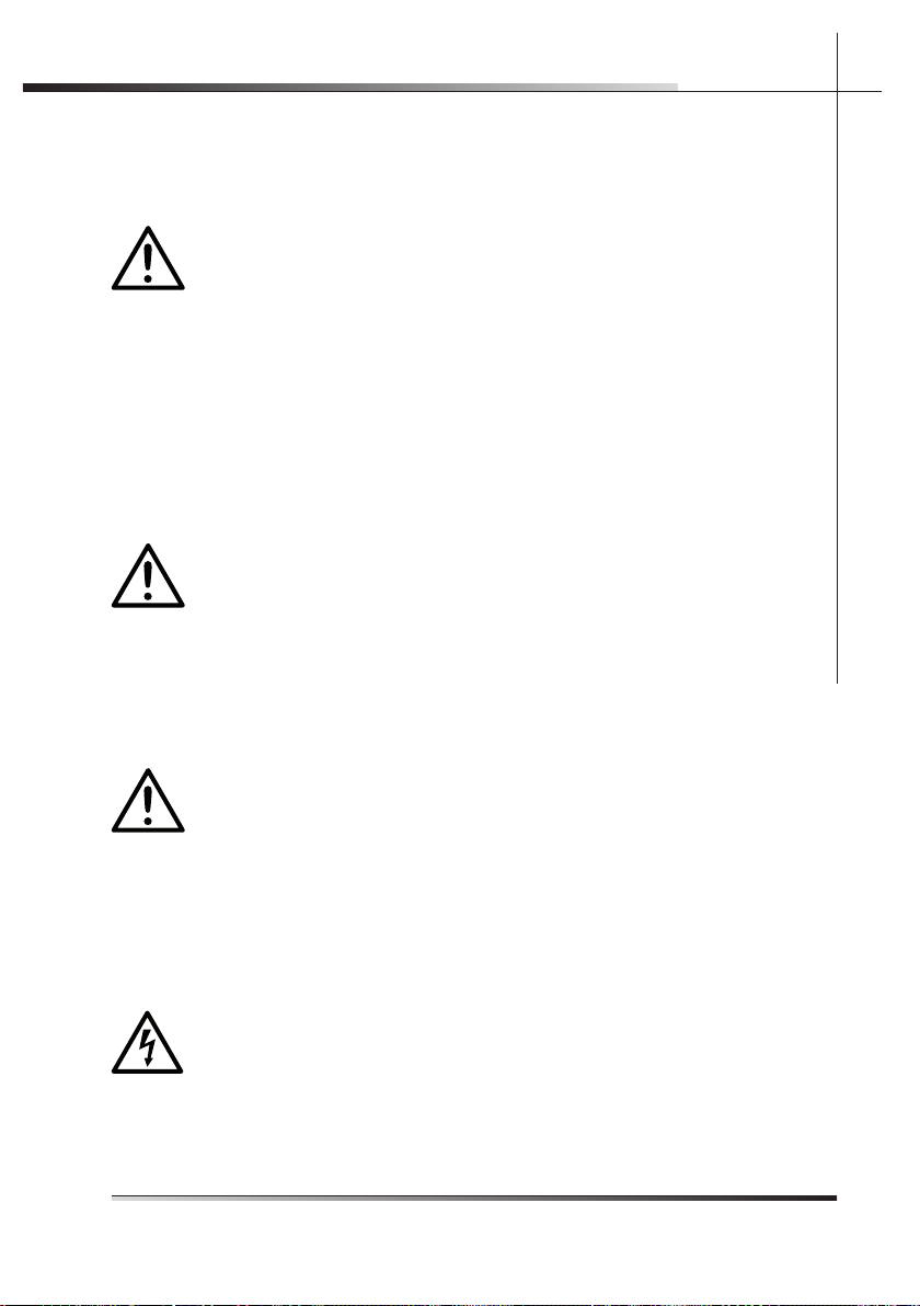
Symbols used in this manual (see tab. 1-01)
DANGER. This symbol highlights information and warnings which,
if not observed, may compromise personal safety or damage the
appliance.
DANGER OF ELECTROCUTION. This symbol highlights information
and warnings of an electrical nature which, if not observed, may
compromise personal safety or damage the appliance.
This symbol highlights general information and warnings.
Tab. 1-01
Page 7
Rev 0.0 5
WARNINGS EN
2 SAFETY INFORMATION
THIS MANUAL FORMS AN INTEGRAL PART OF THE APPLIANCE:
IT MUST ALWAYS BE KEPT INTACT TOGETHER WITH THE DISHWASHER. BEFORE USING THE APPLIANCE, CAREFULLY READ
ALL THE INSTRUCTIONS CONTAINED IN THIS MANUAL.
INSTALLATION MUST BE PERFORMED BY A QUALIFIED TECHNICIAN, IN COMPLIANCE WITH THE REGULATIONS IN FORCE.
THIS APPLIANCE IS INTENDED FOR DOMESTIC USE AND SIMILAR APPLICATIONS SUCH AS THE STAFF KITCHENS OF SHOPS,
OFFICES AND OTHER WORKPLACES, INSTITUTIONS, AND FOR
THE USE OF GUESTS AT HOTELS, HOSTELS, BED AND BREAKFAST ESTABLISHMENTS AND OTHER RESIDENTIAL FACILITIES
AND COMPLIES WITH DIRECTIVES 2006/95/EC AND 2004/108/
EC CURRENTLY IN FORCE, INCLUDING THE PREVENTION AND
ELIMINATION OF RADIO FREQUENCY INTERFERENCE.
THE APPLIANCE IS DESIGNED FOR THE FOLLOWING PURPOSE: WASHING AND DRYING OF DISHES; ANY OTHER USE
SHALL BE CONSIDERED IMPROPER. THE MANUFACTURER
DECLINES ALL RESPONSIBILITY FOR USES OTHER THAN
THOSE DESCRIBED ABOVE.
INSTALLATION, REPAIRS AND SERVICING MUST BE PERFORMED BY QUALIFIED AND AUTHORIZED TECHNICIANS.
AS WELL AS INVALIDATING THE WARRANTY, WORK CARRIED
OUT BY UNAUTHORIZED PERSONS MAY GENERATE HAZARDS.
INSTALLATION MUST BE PERFORMED IN COMPLIANCE WITH
ALL THE DIRECTIVES IN FORCE IN THE COUNTRY OF INSTALLATION AND, IF THESE DO NOT EXIST: IN THE UNITED STATES THE
NATIONAL ELECTRIC CODE; IN CANADA THE CANADIAN ELECTRIC CODE C22.1 - LATEST EDITION/PROVINCIAL AND MUNICIPAL CODES AND/OR LOCAL CODES.
THE NAME PLATE FEATURING THE TECHNICAL DATA, SERIAL
NUMBER AND MARKINGS IS VISIBLY POSITIONED ON THE INNER EDGE OF THE DOOR. THE NAMEPLATE ON THE INNER
EDGE OF THE DOOR MUST NEVER BE REMOVED.
THIS APPLIANCE IS NOT SUITABLE FOR USE ON BOATS, CARAVANS OR THE LIKE. DISHWASHERS CERTIFIED FOR DOMESTIC
USE ARE NOT SUITABLE FOR AUTHORISED FOOD FACTORIES.
Page 8

6 Rev 0.0
WARNINGSEN
CHECK THAT THE VOLTAGE, FREQUENCY AND PROTECTION OF
THE DOMESTIC MAINS POWER SUPPLY MATCH THE RATINGS
ON THE NAME PLATE OF THE APPLIANCE.
TWO PEOPLE WEARING SAFETY GLOVES ARE REQUIRED
TO LIFT THE DISHWASHER.
DO NOT LEAVING DISCARDED PACKAGING MATERIALS UNSUPERVISED WITHIN THE HOME. SEPARATE THE VARIOUS PACKAGING MATERIALS AND TAKE THEM TO THE NEAREST SORTED
WASTE COLLECTION CENTRE. KEEP CHILDREN, PHYSICALLY
AND/OR MENTALLY IMPAIRED ADULTS, AND ANIMALS AWAY
FROM PACKAGING WASTE; DANGER OF SUFFOCATION.
BEFORE PROCEEDING WITH INSTALLATION, DISCONNECT THE
MAINS POWER SUPPLY FROM THE WORK AREA.
DURING INSTALLATION, TAKE CARE NOT TO INJURE YOURSELF
ON THE SHARP EDGES OF THE APPLIANCE; WEAR SAFETY
GLOVES.
THE APPLIANCE MUST BE PROVIDED WITH A GROUND CONNECTION IN ACCORDANCE WITH THE ELECTRICAL SAFETY
REGULATIONS IN FORCE. IF IN DOUBT, HAVE THE SYSTEM
CHECKED BY A QUALIFIED ELECTRICIAN.
THE MANUFACTURER DECLINES ALL RESPONSIBILITY FOR
DAMAGE TO PERSONS OR PROPERTY RESULTING FROM
THE FAILURE TO GROUND THE APPLIANCE OR FROM A DEFECTIVE GROUND CONNECTION.
DO NOT USE APPLIANCES WHICH HAVE BEEN DAMAGED DURING TRANSIT! IF IN DOUBT, CONSULT YOUR DEALER. THE APPLIANCE MUST BE INSTALLED AND CONNECTED IN ACCORDANCE
WITH THE INSTRUCTIONS PROVIDED BY THE MANUFACTURER
OR BY A QUALIFIED TECHNICIAN.
Page 9

Rev 0.0 7
WARNINGS EN
DO NOT OPERATE THE DISHWASHER UNLESS ALL THE OUTER
PANELS HAVE BEEN POSITIONED CORRECTLY.
IMMEDIATELY AFTER INSTALLATION, BRIEFLY TEST THE APPLIANCE FOLLOWING THE INSTRUCTIONS INDICATED BELOW. IF
THE DISHWASHER FAILS TO OPERATE CORRECTLY, DISCONNECT IT FROM THE ELECTRICAL POWER SUPPLY AND CALL THE
NEAREST TECHNICAL SERVICE CENTRE. DO NOT ATTEMPT TO
REPAIR THE APPLIANCE.
DO NOT USE EXTENSION CORDS, ADAPTORS OR SHUNT CONNECTIONS IN ORDER TO AVOID THE POSSIBILITY OF OVERHEATING OR BURNING, WITH CONSEQUENT FIRE HAZARD.
THE MANUFACTURER DECLINES ALL RESPONSIBILITY FOR DAMAGE TO PERSONS, ANIMALS OR PROPERTY RESULTING FROM FAILURE TO OBSERVE THE ABOVE
PRECAUTIONS, FROM TAMPERING WITH EVEN A SINGLE
COMPONENT OF THE APPLIANCE, OR FROM THE USE OF
UNORIGINAL SPARE PARTS.
IF IN DOUBT ABOUT THE CONTENTS OF THIS MANUAL,
CONTACT THE TECHNICAL ASSISTANCE SERVICE.
Page 10

8 Rev 0.0
INSTALLATION INSTRUCTIONSEN
3 INSTALLATION MATERIAL
To install the dishwasher correctly, the following materials are required:
• Phillips screwdriver (ref. A fi g. 3-01);
• spirit level (ref. B fi g. 3-01);
• tape measure (ref. C fi g. 3-01);
• compass saw (ref. D fi g. 3-01);
• pencil (ref. E fi g. 3-01);
• fi le (ref. F fi g. 3-01);
• 13 mm open-ended wrench (ref. G fi g. 3-01);
• plumbing pliers (ref. H fi g. 3-01);
• drill (ref. I fi g. 3-01);
• safety gloves (ref. L fi g. 3-01).
Fig. 3-01
A
B
C
D
E
F
G
H
I
L
Page 11
Rev 0.0 9
INSTALLATION INSTRUCTIONS EN
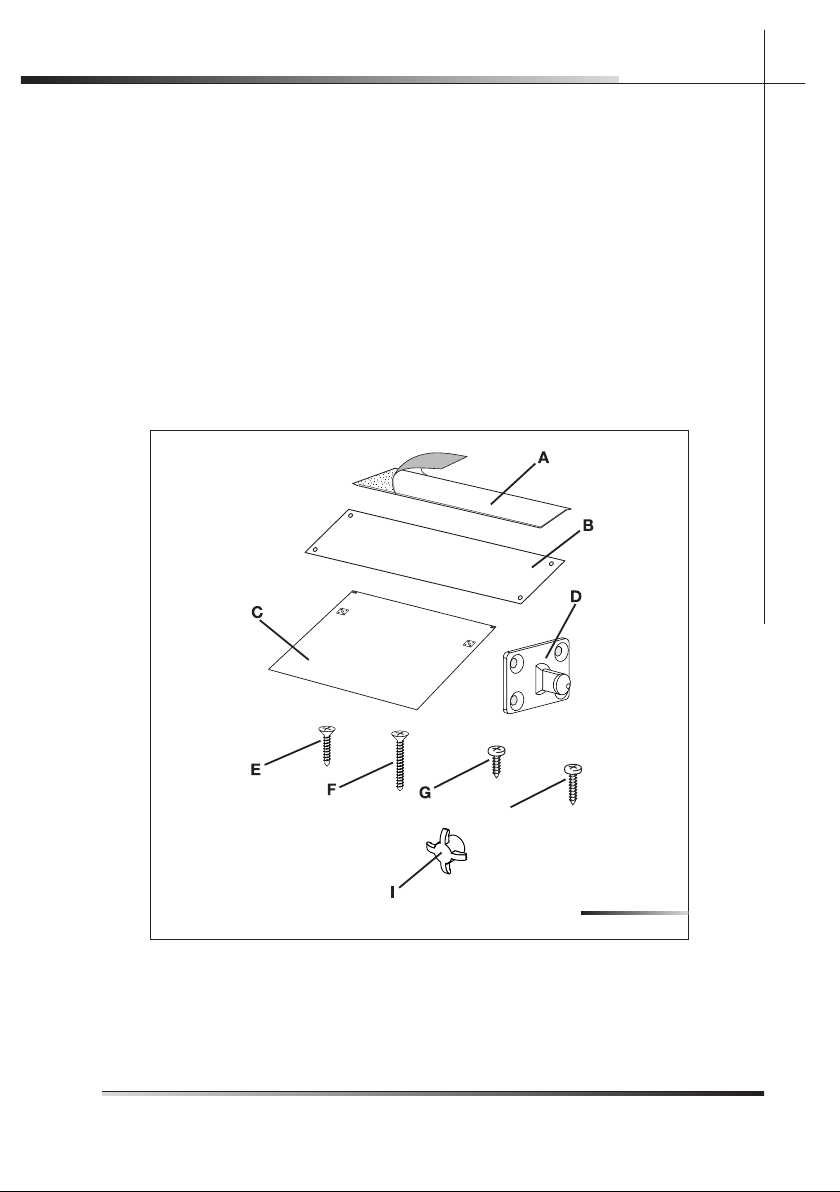
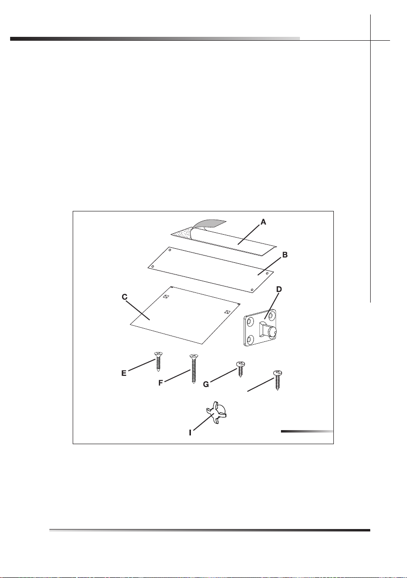
3.1 Kit supplied with dishwasher (DWTPC10FI)
The kit supplied with the dishwasher comprises:
• 1 adhesive steam guard (depending on the model) (ref. A fi g. 3-02);
• 1 steel adhesive steam guard (depending on the model) (ref. B fi g. 3-02)*;
• 1 template for door panel (ref. C fi g. 3-02);
• 2 hooks for door panel (ref. D fi g. 3-02);
• 8 screws for securing the door panel hooks (ref. E fi g. 3-02);
• 2 screws for securing the door (ref. F fi g. 3-02);
• 4 screws for fi xing the dishwasher to the adjacent walls (ref. G fi g. 3-02);
• 2 upper fi xing screws (ref. H fi g. 3-02);
• 2 screw caps (ref. I Fig. 3-02);
Accessories A and G also provided with the model DWTPC5FC
H
* The adhesive protection is suitable for kitchens with worktops that do not allow the
steel protection to be fi xed with screws (e.g.:+ marble or masonry), but it can be also
used with other materials.
Fig. 3-02
Page 12

10 Rev 0.0
INSTALLATION INSTRUCTIONSEN
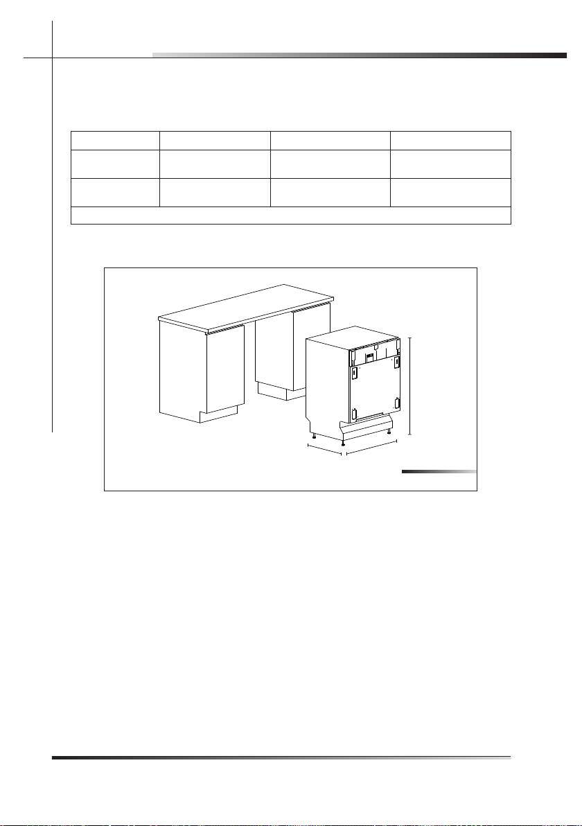
4 DIMENSIONS OF DISHWASHER (See fi g. 4-01)
Model A (height) B (width) C (depth)
DWTPC10FI
82 cm - 89 cm
32-9/32” - 35-3/64”
59.7 cm ÷ 59,9 cm
23-1/2” ÷ 23-37/64”
55 cm
21-21/32”
DWTPC5FC
82 cm - 89 cm
32-9/32” - 35-3/64”
59.7 cm ÷ 59.9 cm
23-1/2” ÷ 23-37/64”
60 cm
23-5/8”
Tab. 4-01
A
B
C
Fig. 4-01
Page 13

Rev 0.0 11
INSTALLATION INSTRUCTIONS EN
5 INSTALLATION AND HOOK-UP
DURING INSTALLATION, TAKE CARE NOT TO INJURE YOURSELF
ON THE SHARP EDGES OF THE APPLIANCE.
Remove the polystyrene rack blocks. Position the appliance in the chosen installation position. The sides and rear of the appliance can lie against kitchen
units or walls. If the dishwasher is installed next to a heat source, separate it
with a heat insulating panel in order to prevent overheating and malfunctions.
To assure stability, only install built-in appliances under continuous worktops,
securing them to the adjacent kitchen units or worktop with screws.
BUILDING-IN A DISHWASHER UNDERNEATH A CERAMIC HOB IS
ABSOLUTELY FORBIDDEN. A DISHWASHER CAN BE BUILT-IN
UNDERNEATH A CONVENTIONAL HOB PROVIDED THERE IS NO
BREAK IN THE KITCHEN WORKTOP, AND THE DISHWASHER
AND HOB ARE INSTALLED AND SECURED CORRECTLY, SO
THAT NO HAZARDS ARE GENERATED.
MAKE SURE THE DISHWASHER HAS BEEN CORRECTLY INSTALLED AND GROUNDED BY A QUALIFIED FITTER. THIS
SAFETY REQUIREMENT MUST BE MET. IN CASE OF DOUBT,
CALL IN A QUALIFIED FITTER. THE MANUFACTURER DECLINES ALL RESPONSIBILITY FOR DAMAGE TO PERSONS
OR PROPERTY RESULTING FROM THE FAILURE TO GROUND
THE APPLIANCE OR FROM A DEFECTIVE GROUND CONNECTION .
BEFORE PROCEEDING WITH INSTALLATION, DISCONNECT
THE MAINS POWER SUPPLY FROM THE WORK AREA.
Only for free-standing models
• It is strictly forbidden to mount a hob over a free-standing dishwasher.
Page 14

12 Rev 0.0
INSTALLATION INSTRUCTIONSEN
• If the appliance is not in a niche and can therefore be accessed on one
side, cover the door hinge area for safety reasons (cutting hazard). Covers
are available as accessories from specialized retailers or from the Technical
Service Centre.
• To build in the dishwasher, purchase the relative kit from specialized retailers or from the Technical Service Centre.
5.1 Leveling
5.1.2 Levelling the appliance
Level the appliance using the relative adjustable feet (e.g.: ref. A fi g. 5-01); use
an open-ended wrench to rotate the feet until the dishwasher is perfectly level.
Some models are fi tted with just one rear foot which can be adjusted with a
screw located at the bottom front of the appliance (ref. A fi g. 5-02); use a suitable Phillips screwdriver or 8 mm hex head bushing to turn the screw until the
dishwasher is perfectly level.
Use a spirit level to check the appliance is perfectly level (ref. B fi g. 5-01).
Leveling is vital for assuring correct dishwasher operation.
Make sure to leave a gap of at least 3 mm (7/64”) between the top of the dishwasher and the worktop (ref. C fi g. 5-01).
Fig. 5-01
Page 15
Rev 0.0 13
INSTALLATION INSTRUCTIONS EN
Fig. 5-02
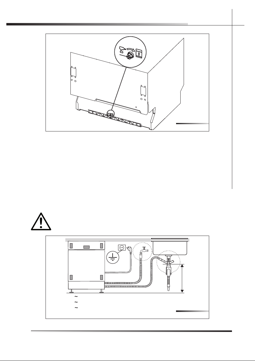
5.2 Connections
Install the dishwasher so as to allow ease of access to the electrical and hydraulic connections through the adjacent unit. These connections must never
be behind the dishwasher.
The inlet and drain hoses can be pointed in all directions. make sure that they
are not bent, crushed or too tight. Tighten the ring nut after pointing the hoses
in the required direction.
Figure 5-03 indicates the distances to maintain between the dishwasher and
the various connections.
FIRE HAZARD!
DO NOT COVER OR CRUSH THE CORD PLUG.
A = 1200 mm / 47”
B = 1500 mm / 59”
C = 1600 mm / 63”
D = min. 400 mm / 16”
A
B
D
C
Fig. 5-03
Page 16

14 Rev 0.0
INSTALLATION INSTRUCTIONSEN
A through hole with a diameter of at least 8 cm (5/32”) is required to pass the
hoses and power cord (ref. A fi g. 5-04).
Make sure there area no rough edges that could damage the power cord or
hoses. If the dishwasher is installed in a metal unit protect the edge of the
through hole for the hoses and power cord with a gasket. Do not use extension
cords when making the electrical connection as these do not guarantee safety.
ATTENTION!
INSTALLING THE DISHWASHER IN A NARROW SPACE MAY BEND
OR CRUSH THE POWER CORD. TAKE GREAT CARE IN ORDER TO
REDUCE THE POSSIBILITY OF DAMAGING THE POWER CORD
WHEN INSTALLING OR REMOVING THE APPLIANCE.
A
5.2.1 Connecting to the water supply
PREVENTING THE RISK OF CLOGGING OR DAMAGE: IF THE
WATER PIPE IS NEW OR HAS NOT BEEN USED FOR A LONG
TIME, BEFORE CONNECTING TO THE WATER SUPPLY CHECK
THAT THE WATER IS CLEAR AND FREE OF IMPURITIES, TO PREVENT DAMAGE TO THE APPLIANCE. THE DISHWASHER MUST
ALWAYS BE CONNECTED TO THE WATER SYSTEM WITH
NEW HOSES; OLD OR USED HOSES MUST NEVER BE REUSED.
Fig. 5-04
Page 17
Rev 0.0 15
INSTALLATION INSTRUCTIONS EN
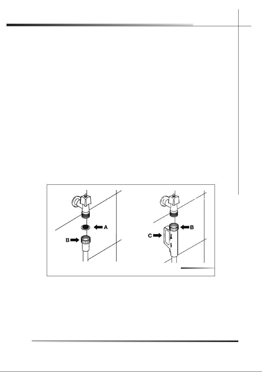
5.2.1.1 Connecting to the water tap
Connect the inlet hose to a threaded ¾” gas cold water tap, fi tting the supplied
fi lter (ref. A fi g. 5-05). Firmly secure the hose by tightening the relative
ring nut with your hands (ref. B fi g. 5-05); fi nish by tightening another
¼ turn using a pair of plumbing pliers. For models fi tted with ACQUASTOP (ref. C fi g. 5-05) the fi lter is already present in the threaded ring nut.
The dishwasher can be fi lled with water at a temperature of less than
60°C (140°F).
If the appliance is fi lled with hot water, washing times will be reduced by about
20 minutes, but effi ciency will be slightly impaired. Make the connection to the
domestic hot water tap using the same methods described for connecting the
appliance to the cold water tap.
• Recommended temperature: 49°C (120°F), max. 60°C (140°F).
• Recommended water pressure: 0.5 - 9 bar (7 -130 PSI).
If the pressure is too high, fi t a pressure reducer.
A rubber hose connected to a sink spray may burst if installed on the
same pipes feeding the dishwasher. If your sink is fi tted with this accessory, remove the hose and plug the hole.
Fig. 5-05
Page 18
16 Rev 0.0
INSTALLATION INSTRUCTIONSEN
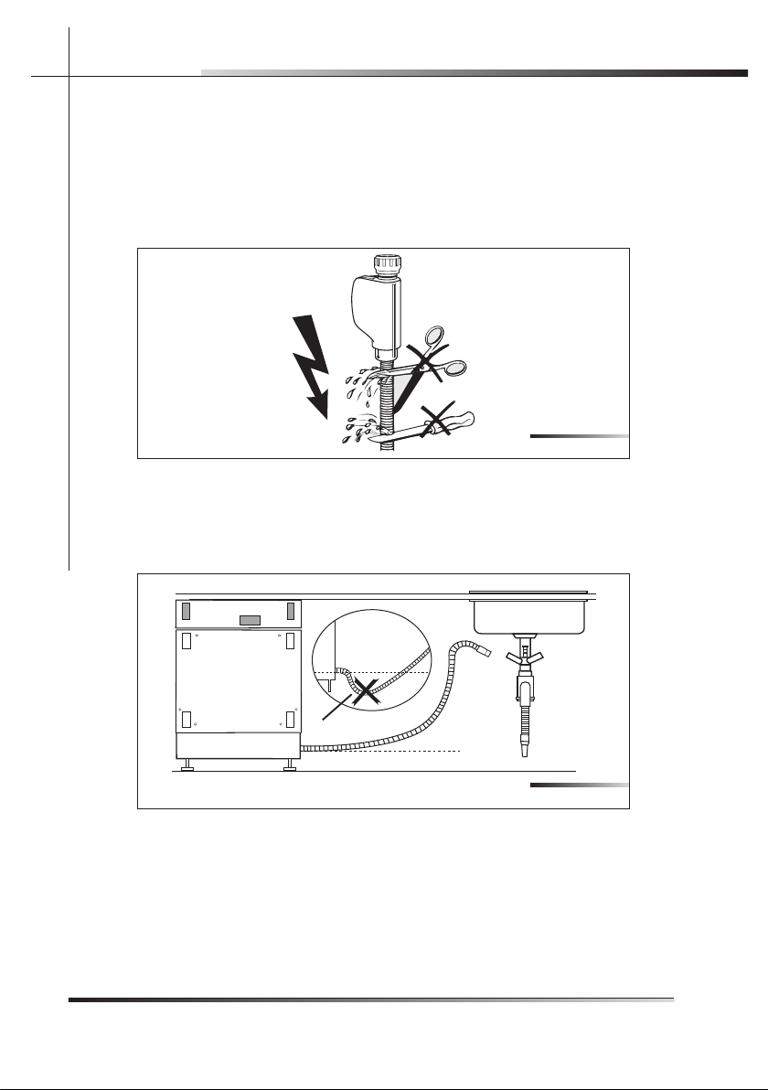
Do not cut the inlet hose (see fi g. 5-06).
If the hose is cut, the dishwasher will not work, water will leak and you may be
injured.
If the hose is too long, wind it up tidily and place it behind the appliance.
The cable harness and electrical components must not come into contact with
the hydraulic system and the water inlet and drain hoses.
When connecting the dishwasher drain hose to the sink make sure that the
hose is not bent (ref. A fi g. 5-07) in order to prevent cracks or breakages that
could damage it.
Fig. 5-07
A
Fig. 5-06
Page 19

Rev 0.0 17
INSTALLATION INSTRUCTIONS EN
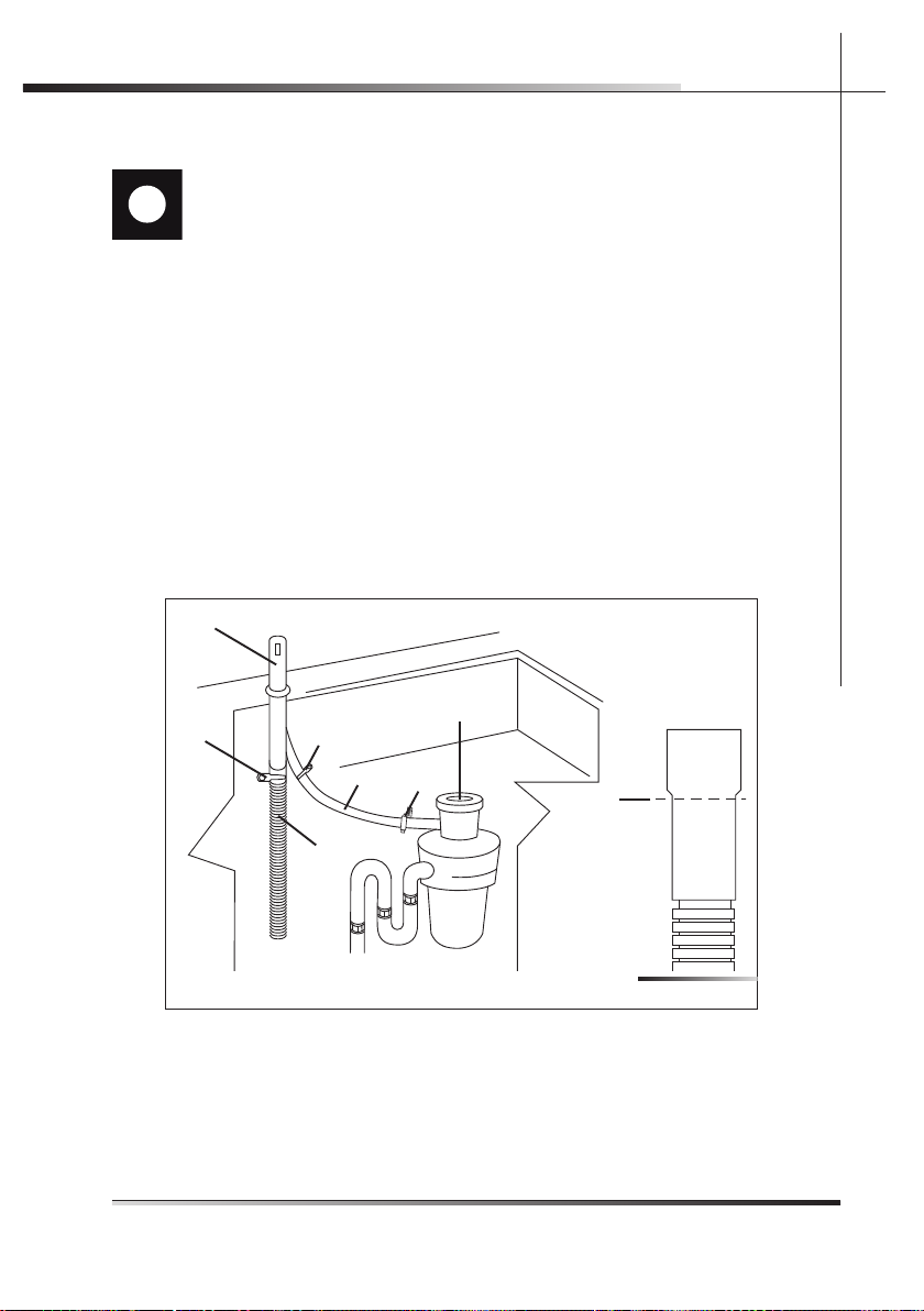
5 .2.1.2 Connecting the drain hose
Connecting to a drain
Insert the relative hose into a drain with a minimum diameter of 4 cm (1-37/64”)
(ref. A fi g. 5-08); alternatively, place the hose on the sink (ref. B fi g. 5-08) using
the supplied hose support (see fi g. 5-9), but taking care to avoid obstructions
or excessive curving. Make sure the hose cannot fall out. For this purpose,
the hose support is fi tted with a hole (ref. A fi g. 5-9) which can be used to fi x
it to the wall or the tap with a piece of string. The free end must lie at a height
ranging from of 30 to 100 cm (from of 1-7/32” to 3-59/64”) (see fi g. 5-08)
and must never be immerged in water. If horizontal extension hoses with a
maximum length of 3m are used, position the drain hose at a maximum height
of 85 cm (3-11/32”) above the fl oor.
Fig. 5-08
A
B
min O4 cm
1-37/64”
min 30 cm
1-7/32”
MAX 100 cm
3-59/64”
Fig. 5-9
A
Page 20

18 Rev 0.0
INSTALLATION INSTRUCTIONSEN
Connecting to a “T” union of the drain circuit
MAKE THE CONNECTION UPLINE FROM THE SIPHON OF THE
DRAIN LINE AND AT LEAST 400 mm (15-3/4”) ABOVE THE FLOOR
ON WHICH THE DISHWASHER WILL BE INSTALLED.
1. Connect the dishwasher drain hose (ref. A fi g. 5-10) to the “T” union (ref. B
fi g. 5-10) of the drain circuit using a 38 to 50 mm (1-1/2 to 2”) screw clamp*
(ref. C fi g. 5-10); if necessary, cut the end of the dishwasher drain hose (ref.
D fi g. 5-10) (do not cut the corrugated section).
* Available from any plumbing stockist
Fig. 5-10
A
C
B
D
Page 21

Rev 0.0 19
INSTALLATION INSTRUCTIONS EN
Connecting to a waste disposal unit with an air gap
MAKE THE CONNECTION UPLINE FROM THE SIPHON OF THE
DRAIN LINE AND AT LEAST 400 mm (15-3/4”) ABOVE THE FLOOR
ON WHICH THE DISHWASHER WILL BE INSTALLED.
1. Remove the cover of the waste disposal unit (ref. A fi g. 5-11).
2. Connect the dishwasher drain hose (ref. B fi g. 5-11) to the air gap (ref. C
fi g. 5-11) using the wide spring clamp (ref. D fi g. 5-11); if necessary, cut the
end of the dishwasher drain hose (ref. E fi g. 5-12) (do not cut the corrugated
section). If the drain hose has been cut, use a 38 to 50 mm (1-1/2 to 2”)
screw clamp*.
3. To connect the air gap (ref. C fi g. 5-11) to the waste disposal unit inlet (ref. F
fi g. 5-11), use a rubber union* (ref. G fi g. 5-11) with spring or screw clamps*
(ref. H fi g. 5-11).
* Available from any plumbing stockist
Fig. 5-11
C
D
B
G
H
H
A
E
Page 22

20 Rev 0.0
INSTALLATION INSTRUCTIONSEN
Connecting to the air gap (no waste disposal unit)
MAKE THE CONNECTION UPLINE FROM THE SIPHON OF THE
DRAIN LINE AND AT LEAST 400 mm (15-3/4”) ABOVE THE FLOOR
ON WHICH THE DISHWASHER WILL BE INSTALLED.
1. Connect the dishwasher drain hose (ref. A fi g. 5-12) to the air gap (ref. B fi g.
5-12) using the wide spring clamp (ref. C fi g. 5-12); if necessary, cut the end
of the dishwasher drain hose (ref. D fi g. 5-12) (do not cut the corrugated
section). If the drain hose has been cut, use a 38 to 50 mm (1-1/2 to 2”)
screw clamp*.
2. To connect the air gap (ref. B fi g. 5-12) to the “T” union (ref. E fi g. 5-12) of the
drain line, use a rubber union* (ref. F fi g. 5-12) with spring or screw clamps*
(ref. G fi g. 5-12).
* Available from any plumbing stockist
Fig. 5-12
B
C
A
F
G
G
D
E
Page 23

Rev 0.0 21
INSTALLATION INSTRUCTIONS EN
Connecting to a waste disposal unit (no air gap)
MAKE THE CONNECTION UPLINE FROM THE SIPHON OF THE
DRAIN LINE AND AT LEAST 400 mm (15-3/4”) ABOVE THE FLOOR
ON WHICH THE DISHWASHER WILL BE INSTALLED.
1. Remove the cover of the waste disposal unit (ref. A fi g. 5-13).
2. Connect the dishwasher drain hose (ref. B fi g. 5-13) to the waste disposal
unit inlet (ref. C fi g. 5-13), using the wide spring clamp (ref. D fi g. 5-13).
Fig. 5-13
B
D
C
A
Page 24

22 Rev 0.0
INSTALLATION INSTRUCTIONSEN
5 .2.2 Electrical connections and warnings
CHECK THAT THE VOLTAGE AND THE FREQUENCY OF THE
MAINS MATCH THE RATINGS ON THE NAME PLATE OF THE APPLIANCE POSITIONED ON THE INNER EDGE OF THE DOOR.
IN THE EVENT OF DAMAGE TO THE SUPPLY CORD, HAVE
IT REPLACED BY THE MANUFACTURER OR AN AUTHORIZED
TECHNICAL SERVICE CENTRE.
THIS APPLIANCE MUST BE GROUNDED. IN CASE OF A MALFUNCTION OF FAULT, THE GROUND REDUCES THE RISK OF
ELECTROCUTION BY PROVIDING THE ELECTRICAL CURRENT
WITH AN ALTERNATIVE, LESS RESISTANT PATH.
THIS APPLIANCE MUST BE GROUNDED. IN CASE OF A MALFUNCTION OF FAULT, THE GROUND REDUCES THE RISK OF
ELECTROCUTION BY PROVIDING THE ELECTRICAL CURRENT
WITH AN ALTERNATIVE, LESS RESISTANT PATH. THIS APPLIANCE IS FITTED WITH A SUPPLY CORD CONTAINING A GROUND
WIRE AND PLUG. FIT THE PLUG INTO A SUITABLE SOCKET, INSTALLED AND GROUNDED IN COMPLIANCE WITH THE LAWS IN
FORCE IN THE COUNTRY OF INSTALLATION.
BEFORE MAKING ELECTRICAL CONNECTIONS, DISCONNECT THE MAINS POWER SUPPLY FROM THE WORK AREA.
Grounding instructions
This appliance is fi tted with a cord with ground wire and plug. Fit the plug into
a suitable socket, installed and grounded in compliance with the laws in force
in the country of installation.
CHECK THAT THE MAINS SUPPLY IN THE PLACE OF INSTALLATION COMPLIES WITH THE REGULATIONS IN FORCE IN THE
COUNTRY OF USE, AND THAT IT IS CORRECTLY GROUNDED.
AN INCORRECTLY CONNECTED GROUND WIRE MAY GENERATE
THE RISK OF ELECTROCUTION. IF IN DOUBT AS TO THE CORRECT GROUNDING OF THE APPLIANCE, CALL IN A QUALIFIED
ELECTRICIAN OR THE TECHNICAL ASSISTANCE SERVICE. DO
NOT CHANGE THE PLUG ATTACHED TO THE APPLIANCE.
IF THE PLUG IS NOT SUITABLE FOR THE SOCKET, CALL IN A
QUALIFIED ELECTRICIAN TO FIT A SUITABLE PLUG.
Page 25

Rev 0.0 23
INSTALLATION INSTRUCTIONS EN
The plug at the end of the power cord and the corresponding socket must be
of the same type and must conform to current regulations governing electrical
appliances. The plug must be accessible after installation. Never remove the
plug by pulling on the wire. If the power cord is damaged, have it replaced
by the manufacturer or an authorized service centre.
DO NOT USE EXTENSION CORDS, ADAPTORS OR SHUNT CONNECTIONS IN ORDER TO AVOID THE POSSIBILITY OF OVERHEATING OR BURNING, WITH CONSEQUENT FIRE HAZARD.
IN THE EVENT OF DAMAGE TO THE SUPPLY CORD, HAVE IT REPLACED BY THE MANUFACTURER OR AN AUTHORIZED TECHNICAL SERVICE CENTRE IN ORDER TO AVOID ANY RISK.
5.3 Commissioning
5.3.1 Installation procedure
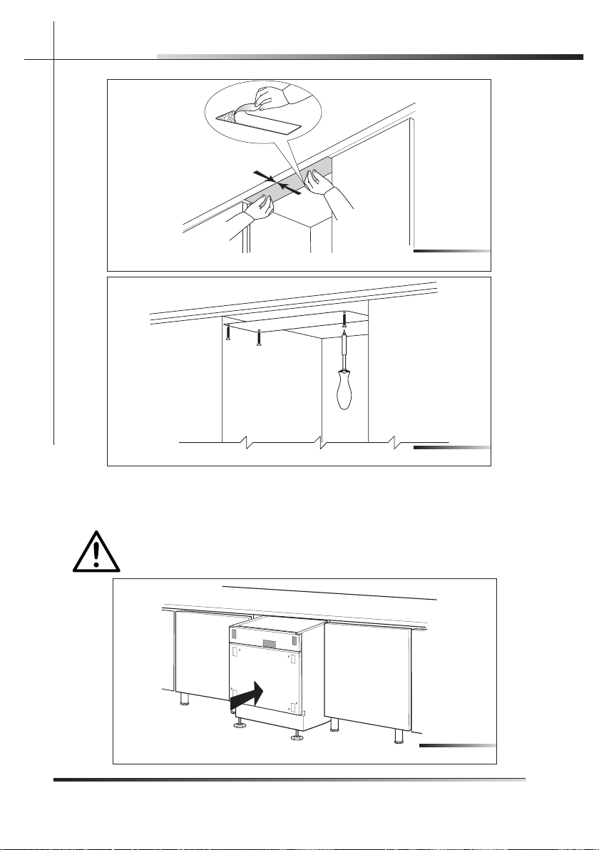
Clean the underneath of the worktop lying over the dishwasher door (see fi g.
5-14) and apply the steam guard, as shown in fi g. 5-15 (see fi g. 5-15 if the
adhesive guard is applied; see fi g. 5-16 if the steel guard is applied). This guard
protects the worktop from steam and condensation when the door of the dishwasher is opened at the end of the washing cycle.
Fig. 5-14
Page 26
24 Rev 0.0
INSTALLATION INSTRUCTIONSEN
Push the dishwasher into position, taking care not to twist or crush the power
cord or hoses (see fi g. 5-17).
TWO PEOPLE WEARING SAFETY GLOVES ARE NEEDED TO PUSH
THE DISHWASHER INTO PLACE.
Fig. 5-15
Fig. 5-16
Fig. 5-17
Page 27

Rev 0.0 25
INSTALLATION INSTRUCTIONS EN
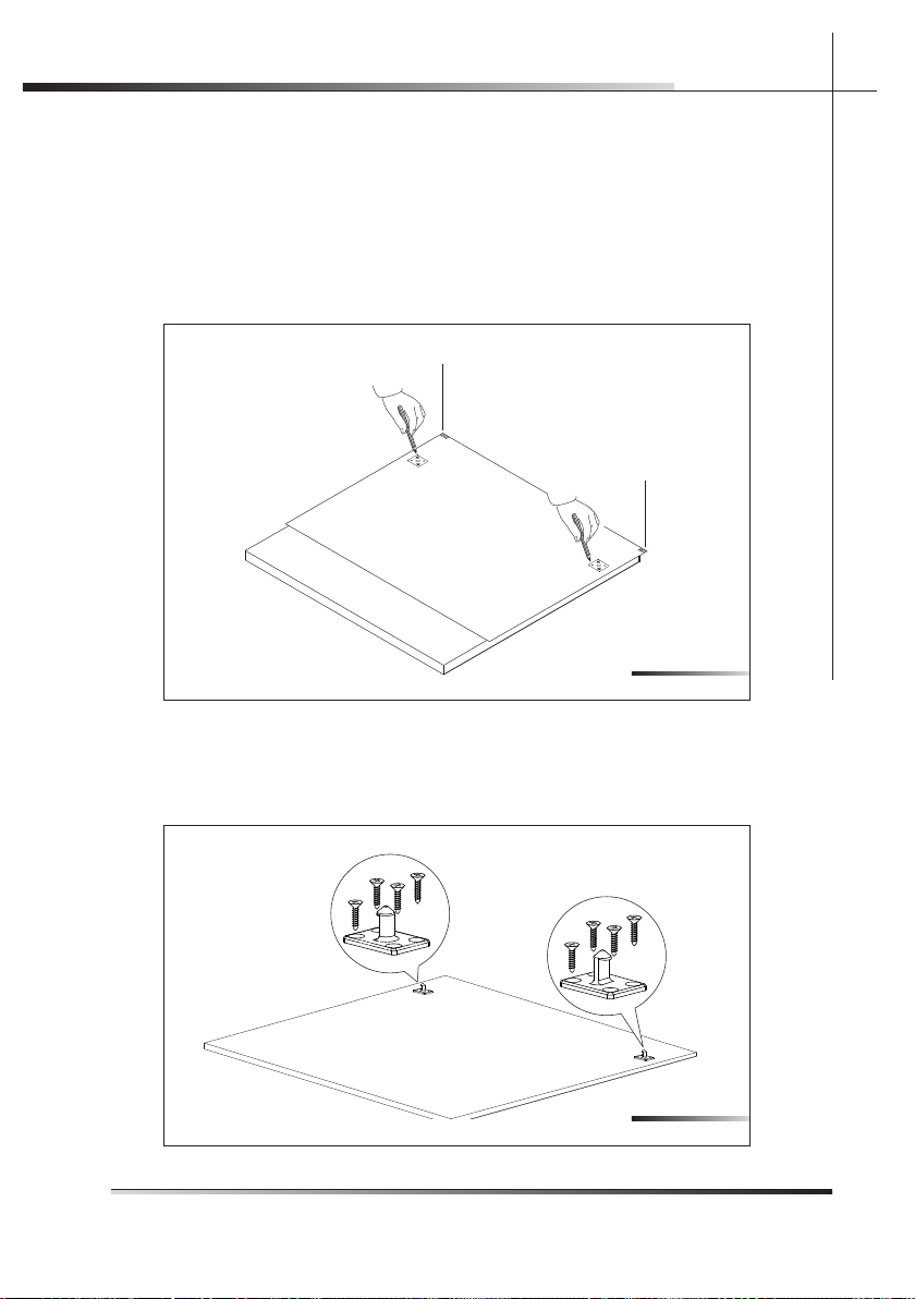
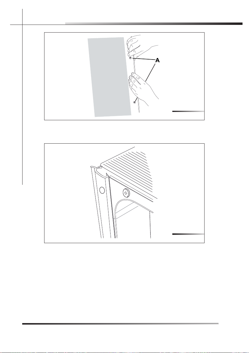
5.3.2 Procedure for mounting the door panel (DWTPC10FI)
Mount the door panel.
Place the template on the inner surface of the panel, centering it along the upper side and matching up the reference locators (ref. A fi g. 5-18); mark the position of the door hooks with a pencil (see fi g. 5-18). Remove the template and
use a drill with a suitable bit to make holes at the points marked on the panel.
A
A
Use the screwdriver to secure the door hooks with the 8 supplied screws (see
fi g. 5-19) at the marked reference points.
Fig. 5-18
Fig. 5-19
Page 28

26 Rev 0.0
INSTALLATION INSTRUCTIONSEN
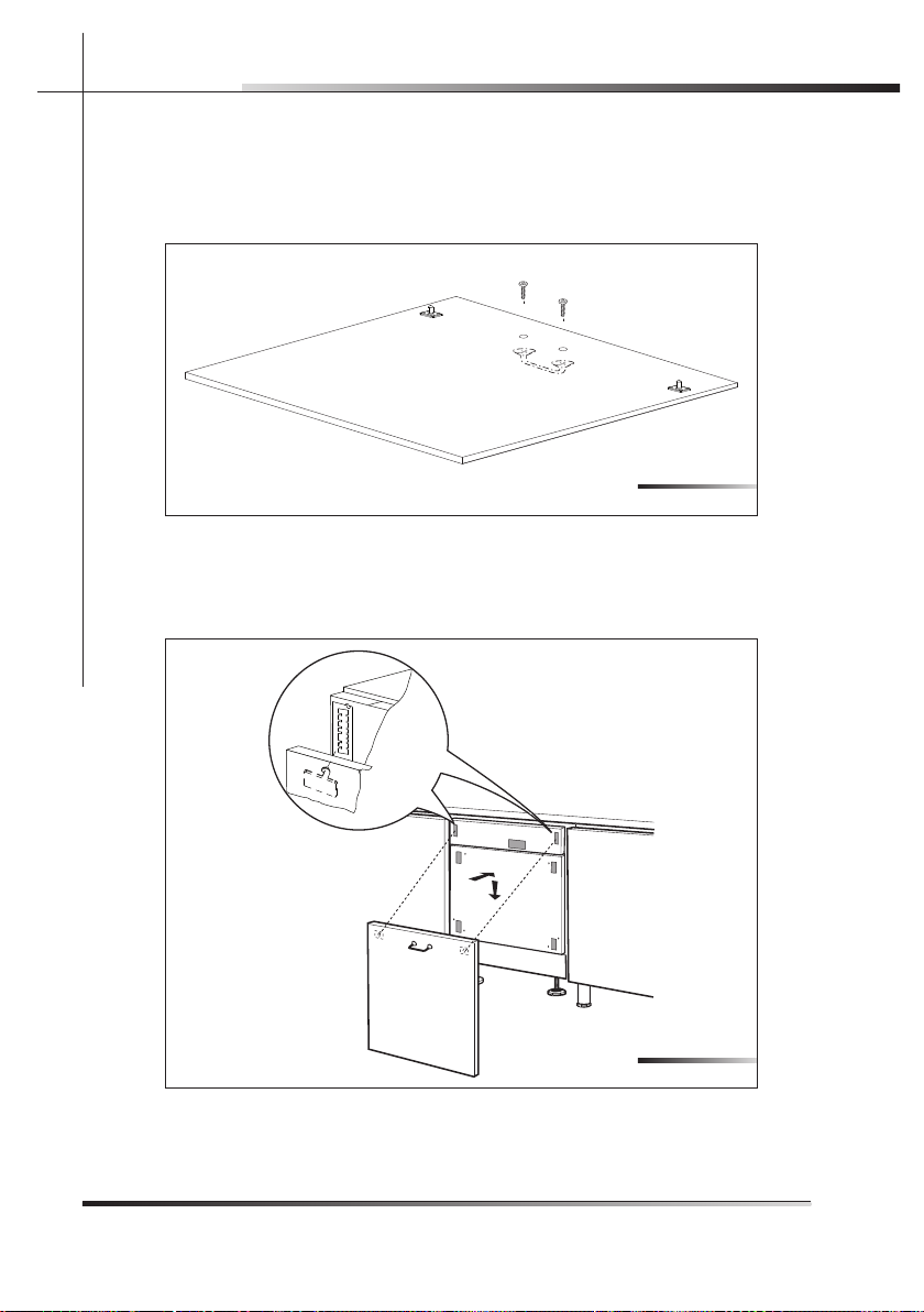
Drill holes for the panel handle using a drill with a suitable bit. Use the screwdriver to secure the door handle before hooking the panel to the dishwasher
(see fi g. 5-20).
N.B.: the screws are not supplied.
Attach the door panel: fi t the hooks into their slots on the dishwasher and allow
the panel to slide downwards and slip in to place (see fi g. 5-21).
1
2
Fig. 5-20
Fig. 5-21
Page 29
Rev 0.0 27
INSTALLATION INSTRUCTIONS EN
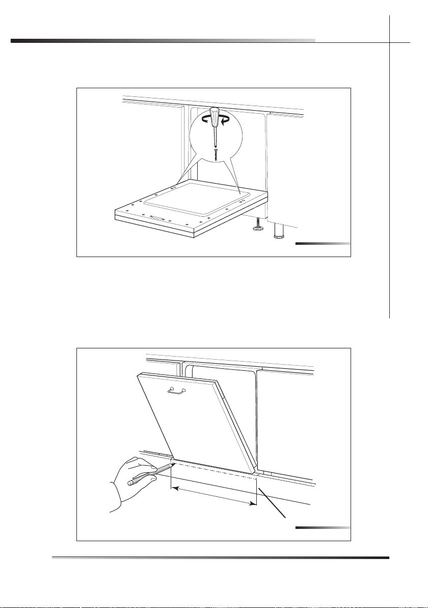
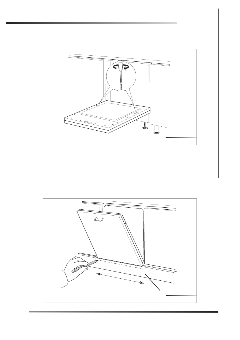
Secure the door to the panel with the supplied screws. The panel must have a
minimum thickness of 20 mm (25/32”) (see fi g. 5-22).
DWTPC10FI-DWTPC5FC
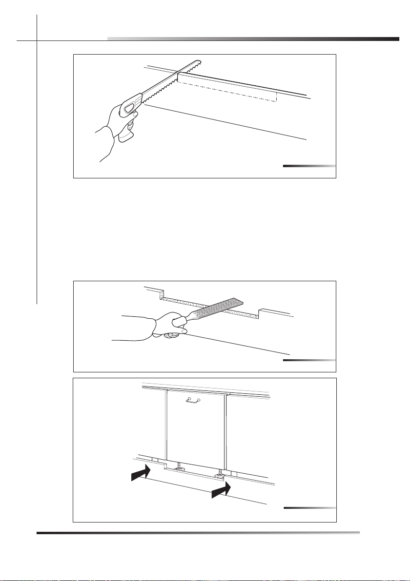
Make sure the dishwasher door, complete with panel, opens comfortably and
that the base plate (ref. A fi g. 5-23) does not prevent it from opening fully. If the
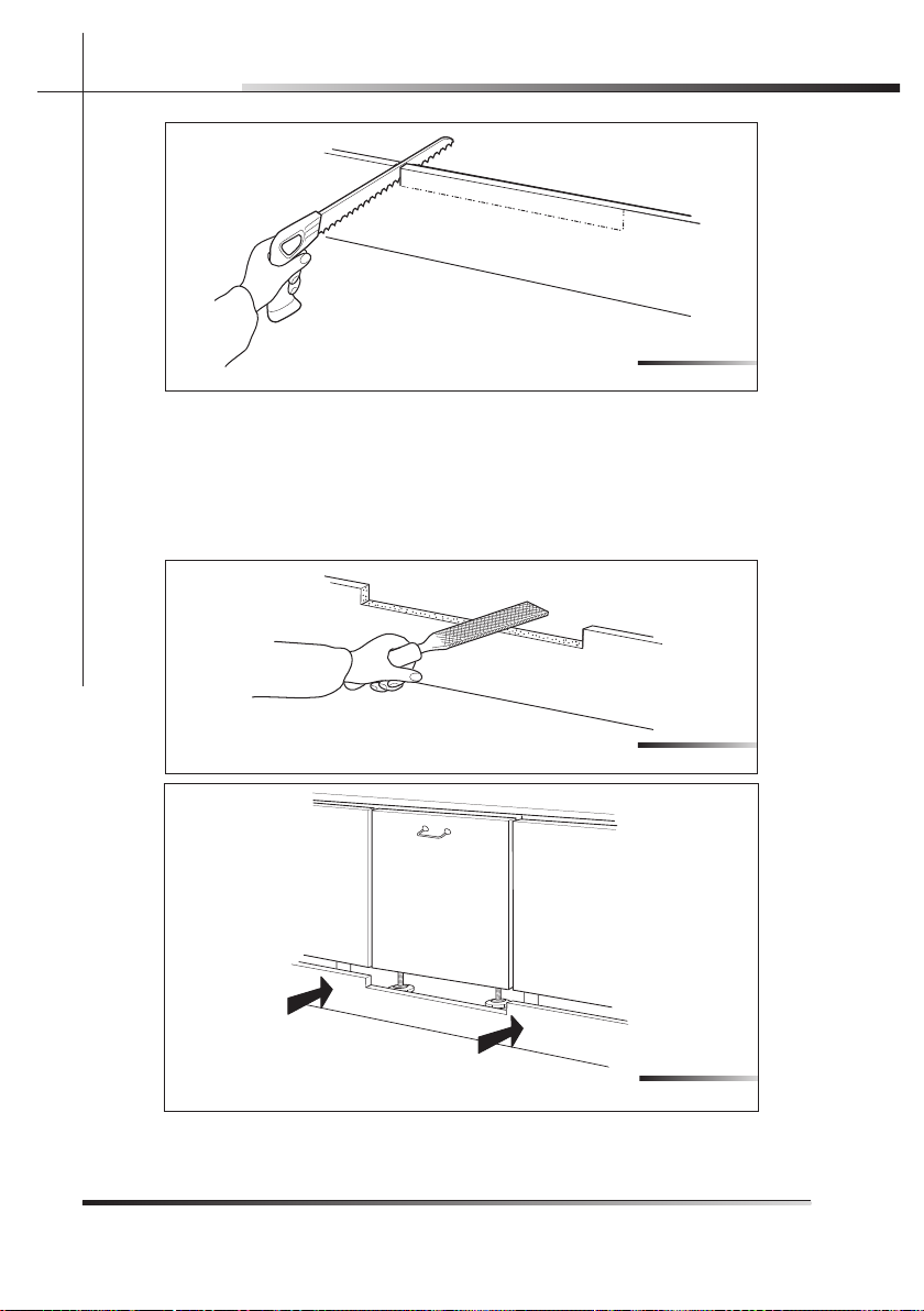
base plate prevents the door from opening, mark out the section to remove
(see fi g. 5-23), take out the base plate and cut it along the marking using a
compass saw (see fi g. 5-24).
605 m
m (2
4.2”)
A
Fig. 5-22
Fig. 5-23
Page 30
28 Rev 0.0
INSTALLATION INSTRUCTIONSEN
5.3.3 Completion of installation (DWTPC10FI-DWTPC5FC)
Finish the cut with a fi le (see fi g. 5-25) in order to remove any burrs and/or
imperfections. Put back the base plate (see fi g. 5-26) and try to open the dishwasher door fully; if the base plate still obstructs the door, repeat the above
operations.
Fig. 5-24
Fig. 5-25
Fig. 5-26
Page 31
Rev 0.0 29
INSTALLATION INSTRUCTIONS EN
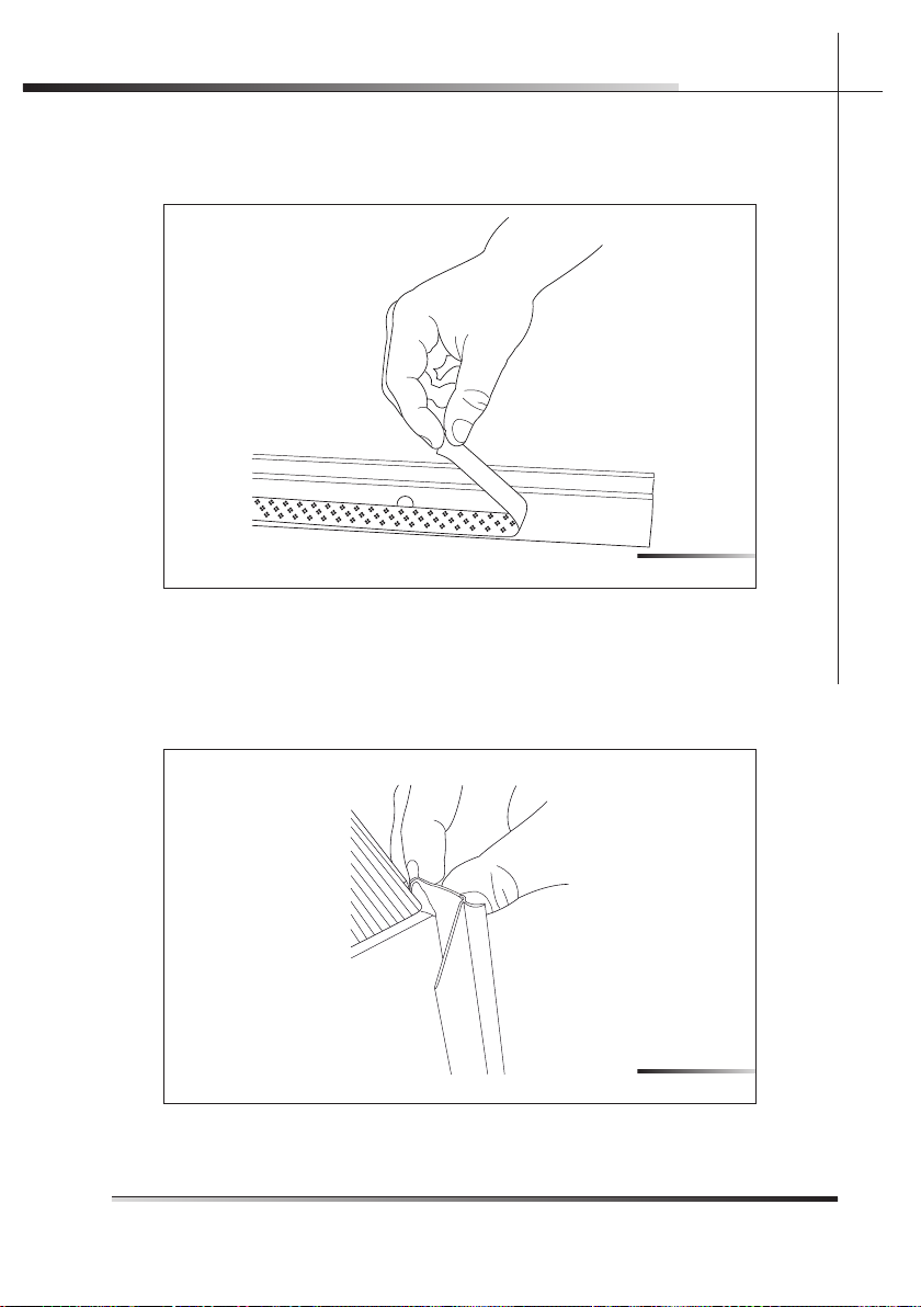
Before securing the dishwasher to the adjacent units, attach the gaskets to
the sides.
Remove the adhesive band on the gasket (see fi g. 5-27).
Fix the gasket to the dishwasher, inserting it in the seat on the sides towards
the front (see fi g. 5-28), and making sure that the long side of the gasket, the
one with the hole for inserting the screw, is attached to the outside of the dishwasher; the hole in the long side must match the hole in the dishwasher (see
ref. A fi g. 5-29). Make sure the gasket adheres perfectly to the dishwasher.
Fig. 5-27
Fig. 5-28
Page 32

30 Rev 0.0
INSTALLATION INSTRUCTIONSEN
Fig. 5-30 shows the state of the dishwasher after the above operations are
performed.
Tighten the supplied screws with a screwdriver; this operation defi nitively fi xes
the dishwasher to the adjacent units; cover the side holes using the supplied
plugs (ref. A fi g. 5-31).
Fig. 5-29
Fig. 5-30
Page 33

Rev 0.0 31
EN
5.4 Testing
After installation, test the dishwasher by starting a work cycle. Check for leaks
and make sure the appliance does not malfunction.
Fig. 5-31
Page 34

Rev 0.0 1
SOMMAIRE
FR
Sommaire
1 INTRODUCTION ........................................................................................3
2 AVERTISSEMENTS SUR LA SÉCURITÉ .....................................................5
3 MATÉRIEL NÉCESSAIRE POUR L’INSTALLATION .....................................8
3.1 Kit fourni avec le lave-vaisselle.................................................................... 9
4 DIMENSIONS LAVE-VAISSELLE ..............................................................10
5 INSTRUCTIONS POUR L’INSTALLATION ET LA POSE ............................11
5.1 Mise de niveau ......................................................................................... 12
5.1.1 Mise de niveau de l’appareil ..................................................................... 12
5.2 Réalisation des branchements..................................................................13
5.2.1 Raccordement au réseau hydrique ...........................................................14
5.2.1.1 Raccordement à la prise d’eau ................................................................. 15
5.2.1.2 Raccordement du tuyau d’évacuation ...................................................... 17
5.2.2 Branchement électrique et avertissements ............................................... 22
5.3 Pose du lave-vaisselle .............................................................................. 23
5.3.1 Procédure de pose du lave-vaisselle ........................................................23
5.3.2 Procédure de montage panneau de la porte ............................................25
5.3.3 Achèvement de la pose du lave-vaisselle .................................................. 28
5.4 Essai .......................................................................................................31
Page 35

2 Rev 0.0
FR
Page 36

Rev 0.0 3
INTRODUCTION
FR
1 INTRODUCTION
Nous vous remercions d’avoir choisi l’un de nos produits. Pour
connaître les conditions les plus appropriées pour une utilisation
correcte et sûre du lave-vaisselle, lisez attentivement les instructions
de ce manuel. Les paragraphes sont organisés rationnellement, de
façon à proposer pas à pas les instructions pour installer l’appareil.
Les textes sont facilement compréhensibles et sont illustrés par des
images détaillées. Ce manuel, d’une consultation facile, est conçu
pour offrir des réponses aux questions qui peuvent surgir au sujet de
l’installation du lave-vaisselle.
Le manuel comprend les sections suivantes :
INTRODUCTION : cette section contient des informations génériques concernant le manuel.
AVERTISSEMENTS : cette section contient une série d’avertissements concernant la sécurité lors de l’installation du lave-vaisselle.
INSTRUCTIONS POUR L’INSTALLATEUR : elles sont destinées au
technicien qualifi é qui doit effectuer l’installation, la mise en service et l’essai de l’appareil.
Nomenclature des fi gures et des tableaux :
l’encadré qui contient les fi gures reporte, en bas sur la droite, la
numérotation progressive de celles-ci. Un exemple de numérotation est “Fig. 4-01”, où le premier chiffre (4) correspond au chapitre d’appartenance de la fi gure, tandis que le deuxième chiffre (01)
correspond au numéro progressif de la fi gure au sein du chapitre
4 (dans l’exemple, la Fig. 4-01 correspond à la première fi gure du
chapitre 4). La numérotation des tableaux suit le même principe
avec, au lieu de “Fig. ”, la notation “Tab.” (par ex. Tab. 4-01 correspond au premier tableau du chapitre 4). Si un même tableau occupe
plusieurs pages, une lettre est ajoutée après le chiffre progressif (par
ex. “Tab. 4-01a”, Tab. 4-01b”).
Page 37

4 Rev 0.0
INTRODUCTION
FR
Symboles utilisés dans ce manuel (voir tab. 1-01)
DANGER. Ce symbole indique des informations et avertissements
qui doivent impérativement être respectés pour ne pas compromettre
la sécurité des personnes ou endommager l’appareil.
DANGER ÉLECTRIQUE. Ce symbole indique des informations
et avertissements concernant les circuits électriques qui doivent
impérativement être respectés pour ne pas compromettre la sécurité
des personnes ou endommager l’appareil.
Ce symbole indique des informations et avertissements de caractère
général.
Tab. 1-01
Page 38

Rev 0.0 5
AVERTISSEMENTS
FR
2 AVERTISSEMENTS SUR LA SÉCURITÉ
CE MODE D’EMPLOI EST PARTIE INTÉGRANTE DE L’APPAREIL:
IL FAUT TOUJOURS LE CONSERVER INTACT PRÈS DE L’APPAREIL. AVANT L’UTILISATION, NOUS CONSEILLONS UNE LECTURE ATTENTIVE DE TOUTES LES INDICATIONS QU’IL CONTIENT.
L’INSTALLATION DEVRA ÊTRE EFFECTUÉE PAR UN PERSONNEL
QUALIFIÉ ET CONFORMÉMENT AUX NORMES EN VIGUEUR. CET
APPAREIL EST PRÉVU POUR UNE UTILISATION DE TYPE DOMESTIQUE ET POUR TOUTE AUTRE APPLICATION DU MÊME GENRE,
PAR EXEMPLE, POUR LE PERSONNEL DANS LA CUISINE DES
BOUTIQUES, BUREAUX ET AUTRES LIEUX DE TRAVAIL, DANS LES
COMMUNAUTÉS, POUR LES CLIENTS DANS LES HÔTELS, AUBERGES, BED AND BREAKFAST ET TOUTE AUTRE STRUCTURE
RÉSIDENTIELLE. IL RÉPOND AUX DIRECTIVES 2006/95/CE ET
2004/108/CE ACTUELLEMENT EN VIGUEUR, Y COMPRIS LA PRÉVENTION ET L’ÉLIMINATION DES BROUILLAGES. L’APPAREIL EST
CONSTRUIT POUR EXERCER LA FONCTION SUIVANTE: LAVAGE
ET SÉCHAGE DE LA VAISSELLE; TOUT AUTRE EMPLOI EST À
CONSIDÉRER COMME ÉTANT IMPROPRE. LE CONSTRUCTEUR
DÉCLINE TOUTE RESPONSABILITÉ POUR DES EMPLOIS
DIFFÉRENTS DE CEUX ÉTANT INDIQUÉS.
L’INSTALLATION ET LES INTERVENTIONS DE RÉPARATION
OU ASSISTANCE DOIVENT ÊTRE EXÉCUTÉES PAR DU PERSONNEL TECHNIQUE QUALIFIÉ ET AUTORISÉ. LES INTER-
VENTIONS EXÉCUTÉES PAR DU PERSONNEL NON AUTORISÉ
PEUVENT ÊTRE DANGEREUSES ET, DE PLUS, COMPORTENT LA
PERTE DE LA GARANTIE. L’INSTALLATION DOIT ÊTRE EXÉCUTÉE
CONFORMÉMENT AUX DIRECTIVES DU PAYS D’INSTALLATION
DU LAVE-VAISSELLE ET, À DÉFAUT DE CELLES-CI : AUX ÉTATSUNIS, LE NATIONAL ELECTRIC CODE ; AU CANADA, LE CANADIAN ELECTRIC CODE C22.1 - LATEST EDITION/PROVINCIAL
AND MUNICIPAL CODES AND/OR LOCAL CODES.
LA PLAQUE D’IDENTIFICATION, AVEC LES DONNÉES TECHNIQUES, LE NUMÉRO DE MATRICULE ET LE MARQUAGE, EST
POSITIONNÉE DE FAÇON VISIBLE SUR LE BORD INTERNE DE LA
PORTE DU LAVE-VAISSELLE. LA PLAQUE D’IDENTIFICATION
SITUÉE SUR LE BORD INTERNE DE LA PORTE NE DOIT JAMAIS ÊTRE ENLEVÉE.
Page 39

6 Rev 0.0
AVERTISSEMENTS
FR
L’APPAREIL N’EST PAS ADAPTÉ POUR UNE UTILISATION MARITIME OU MOBILE COMME, PAR EXEMPLE, SUR DES CAMPINGCARS OU BATEAUX. LES LAVE-VAISSELLE CERTIFIÉS POUR UN
USAGE DOMESTIQUE NE SONT PAS DESTINÉS AUX ÉTABLISSEMENTS ALIMENTAIRES AUTORISÉS.
CONTRÔLER QUE LA TENSION, LA FRÉQUENCE ET LA SENSIBILITÉ DE PROTECTION DE L’INSTALLATION ÉLECTRIQUE GÉNÉRALE CORRESPONDENT AUX INDICATIONS REPORTÉES SUR LA
PLAQUE D’IDENTIFICATION DE L’APPAREIL.
DEUX PERSONNES SONT NÉCESSAIRES POUR SOULEVER
LE LAVE-VAISSELLE. ELLES DOIVENT METTRE DES GANTS
DE SÉCURITÉ POUR EXÉCUTER CETTE OPÉRATION.
NE PAS LAISSER DES RÉSIDUS D’EMBALLAGE SANS SURVEILLANCE DANS L’HABITATION. SÉPARER LES DIFFÉRENTS
MATÉRIAUX DE L’EMBALLAGE À JETER ET LES APPORTER DANS
LE CENTRE DE COLLECTE SÉLECTIVE LE PLUS PROCHE. LES
RÉSIDUS D’EMBALLAGE NE DOIVENT PAS ÊTRE LAISSÉS À LA
PORTÉE DES ENFANTS, DE PERSONNES AYANT DES CAPACITÉS PHYSIQUES ET/OU MENTALES RÉDUITES OU DES ANIMAUX
AFIN D’ÉVITER LE RISQUE D’ASPHYXIE.
AVANT DE PROCÉDER À L’INSTALLATION, COUPER L’ALIMENTATION ÉLECTRIQUE DANS LA ZONE D’INSTALLATION.
PENDANT L’INSTALLATION, FAIRE ATTENTION AUX BORDS
TRANCHANTS SUR LE LAVE-VAISSELLE ; POUR ÉVITER DE SE
BLESSER, METTRE DES GANTS DE SÉCURITÉ.
LA MISE À LA TERRE CONFORMÉMENT AUX MODALITÉS PRÉVUES PAR LES NORMES DE SÉCURITÉ DE L’INSTALLATION
ÉLECTRIQUE EST OBLIGATOIRE. EN CAS DE DOUTE, FAIRE
CONTRÔLER L’INSTALLATION PAR UN ÉLECTRICIEN QUALIFIÉ.
LE FABRICANT DÉCLINE TOUTE RESPONSABILITÉ POUR
LES ÉVENTUELS DOMMAGES AUX PERSONNES OU AUX
CHOSES DÉRIVANT D’UNE MISE À LA TERRE NON EXÉCUTÉE OU DÉFECTUEUSE.
Page 40

Rev 0.0 7
AVERTISSEMENTS
FR
NE PAS UTILISER DES APPAREILS ENDOMMAGÉS PAR LE
TRANSPORT ! EN CAS DE DOUTE, CONSULTER LE REVENDEUR.
L’APPAREIL DOIT ÊTRE INSTALLÉ ET BRANCHÉ CONFORMÉMENT AUX INSTRUCTIONS FOURNIES PAR LE FABRICANT OU
PAR DU PERSONNEL QUALIFIÉ.
NE PAS METTRE EN MARCHE LE LAVE-VAISSELLE SI LES PANNEAUX QUI LE FERMENT NE SONT PAS TOUS POSITIONNÉS
CORRECTEMENT.
IMMÉDIATEMENT APRÈS L’INSTALLATION, EFFECTUER UN BREF
ESSAI DE L’APPAREIL EN SUIVANT LES INSTRUCTIONS REPORTÉES CI-APRÈS. EN CAS DE DÉFAUT DE FONCTIONNEMENT, DÉBRANCHER L’APPAREIL DU RÉSEAU ÉLECTRIQUE ET CONTACTER LE CENTRE SAV LE PLUS PROCHE. NE PAS ESSAYER DE
RÉPARER L’APPAREIL.
NE PAS UTILISER DES PROLONGATEURS, ADAPTATEURS OU
DÉRIVATEURS, CAR ILS PEUVENT PROVOQUER DES SURCHAUFFES OU DES COMBUSTIONS, EN ENTRAÎNANT DES
RISQUES D’INCENDIE.
LE FABRICANT DÉCLINE TOUTE RESPONSABILITÉ POUR
LES DOMMAGES AUX PERSONNES, AUX CHOSES ET AUX
ANIMAUX PROVOQUÉS PAR L’INOBSERVANCE DES PRESCRIPTIONS SUSMENTIONNÉES OU DÉRIVANT DE LA MODIFICATION ABUSIVE, NE SERAIT-CE QUE D’UNE SEULE
PARTIE, DE L’APPAREIL ET DE L’UTILISATION DE PIÈCES DE
RECHANGE NON D’ORIGINE.
EN CAS DE DOUTES SUR LE CONTENU DU MANUEL,
CONTACTER LE SERVICE APRÈS-VENTE.
Page 41

8 Rev 0.0
INSTRUCTIONS POUR L’INSTALLATEUR
FR
3 MATÉRIEL NÉCESSAIRE POUR
L’INSTALLATION
Pour exécuter correctement l’installation du lave-vaisselle, il faut disposer du
matériel suivant :
• tournevis à pointe cruciforme (réf. A fi g. 3-01) ;
• niveau à bulle (réf. B fi g. 3-01) ;
• mètre (réf. C fi g. 3-01) ;
• scie (réf. D fi g. 3-01) ;
• crayon (réf. E fi g. 3-01) ;
• lime (réf. F fi g. 3-01) ;
• clé à fourche de 13 mm (réf. G fi g. 3-01) ;
• pince multiprises (réf. H fi g. 3-01) ;
• perceuse (réf. I fi g. 3-01) ;
• gants de sécurité (réf. L fi g. 3-01).
Fig. 3-01
A
B
C
D
E
F
G
H
I
L
Page 42
Rev 0.0 9
INSTRUCTIONS POUR L’INSTALLATEUR
FR
3.1 Kit fourni avec le lave-vaisselle (DWTPC10FI)
Le kit fourni avec le lave-vaisselle inclut ce qui suit :
• 1 protection contre la vapeur adhésive (selon les modèles) (rep. A, fi g. 3-02) ;
• 1 protection contre la vapeur en acier (selon les modèles) (rep. B, fi g. 3-02)* ;
• 1 gabarit de perçage pour panneau porte (rep. C, fi g. 3-02) ;
• 2 crochets pour panneau porte (rep. D, fi g. 3-02) ;
• 8 vis pour fi xation crochets panneau porte (rep. E, fi g. 3-02) ;
• 2 vis pour fi xation porte (rep. F, fi g. 3-02) ;
• 4 vis pour fi xation aux parois adjacentes (rep. G, fi g. 3-02) ;
• 2 vis fi xation supérieure (rep. H, fi g. 3-02) ;
• 2 cache-vis (rep. I, fi g.3-02) ;
Accessoires A et G sont également fourni avec le modèle DWTPC5FC
H
•
* La protection adhésive est en particulier adaptée pour les cuisines dont le plan de
travail ne permet pas la fi xation de la protection en acier avec des vis (par ex.marbe ou
maçonnerie), mais ellepeut être élegantement utilisée sur d’autres matériaux.
Fig. 3-02
Page 43
10 Rev 0.0
INSTRUCTIONS POUR L’INSTALLATEUR
FR
4 DIMENSIONS LAVE-VAISSELLE (Voir fi g. 4-01)
Modèle A (hauteur) B (largeur) C (profondeur)
DWTPC10FI
82 cm - 89 cm
32-9/32” - 35-3/64”
59,7 cm ÷ 59,9 cm
23-1/2” ÷ 23-37/64”
55 cm
21-21/32”
DWTPC5FC
82 cm - 89 cm
32-9/32” - 35-3/64”
59,7 cm ÷ 59,9 cm
23-1/2” ÷ 23-37/64”
60 cm
23-5/8”
Tab. 4-01
Fig. 4-01
A
B
C
Page 44
Rev 0.0 11
INSTRUCTIONS POUR L’INSTALLATEUR
FR
5 INSTRUCTIONS POUR L’INSTALLATION ET
LA POSE
PENDANT L’INSTALLATION, POUR ÉVITER DE SE BLESSER,
FAIRE ATTENTION AUX BORDS TRANCHANTS SUR LE LAVEVAISSELLE.
Enlever les cales en polystyrène qui bloquent les paniers. Positionner l’appareil
dans le point d’installation. Le lave-vaisselle peut être posé avec les côtés ou
le panneau arrière accolé aux meubles ou aux murs. Si l’on installe le lavevaisselle près d’une source de chaleur, il faut interposer un panneau isolant
thermique afi n d’éviter des surchauffes et des anomalies de fonctionnement.
Pour assurer leur stabilité, installer les appareils encastrables sous plan ou intégrables uniquement sous des plans de travail continus, en les vissant aux
meubles adjacents ou au plan de travail de la cuisine.
IL EST FORMELLEMENT INTERDIT D’ENCASTRER LE LAVEVAISSELLE SOUS UNE TABLE DE CUISSON EN VITROCÉRAMIQUE. IL EST POSSIBLE D’ENCASTRER LE LAVE-VAISSELLE
SOUS UNE TABLE DE CUISSON TRADITIONNELLE À CONDITION
QUE LE PLAN DE TRAVAIL DE LA CUISINE SOIT CONTINU ET
QUE LE LAVE-VAISSELLE ET LA TABLE DE CUISSON SOIENT
MONTÉS ET FIXÉS CORRECTEMENT, DE FAÇON À N’ENTRAÎNER AUCUN RISQUE.
S’ASSURER QUE LE LAVE-VAISSELLE A ÉTÉ INSTALLÉ ET
BRANCHÉ CORRECTEMENT À LA TERRE PAR UN TECHNICIEN QUALIFIÉ. LE RESPECT DE CETTE EXIGENCE DE SÉCURITÉ EST INDISPENSABLE. EN CAS DE DOUTE, S’ADRESSER À DU PERSONNEL QUALIFIÉ. LE FABRICANT DÉCLINE
TOUTE RESPONSABILITÉ POUR LES ÉVENTUELS DOMMAGES AUX PERSONNES OU AUX CHOSES DÉRIVANT
D’UNE MISE À LA TERRE NON EXÉCUTÉE OU DÉFECTUEUSE.
AVANT DE PROCÉDER À L’INSTALLATION, COUPER L’ALIMENTATION ÉLECTRIQUE DANS LA ZONE D’INSTALLATION.
Uniquement pour les modèles pose libre
• Il est formellement interdit de monter un plan de cuisson au-dessus d’un
lave-vaisselle pose libre.
Page 45

12 Rev 0.0
INSTRUCTIONS POUR L’INSTALLATEUR
FR
• Si l’appareil n’est pas inséré dans une niche et qu’il est donc accessible
depuis un côté, il faut protéger la zone de la charnière de la porte pour
des raisons de sécurité (risque de lésions). Les protecteurs sont disponibles
comme accessoire auprès des revendeurs spécialisés ou du Service aprèsvente.
• Pour encastrer le lave-vaisselle, il faut acheter le kit prévu à cet effet auprès
des revendeurs agréés ou du Service après-vente.
5.1 Mise de niveau
5.1.1 Mise de niveau de l’appareil
Mettre de niveau l’appareil par rapport au sol à l’aide des pieds réglables prévus à cet effet (ex. réf. A fi g. 5-01). Pour ce faire, tourner la base d’appui des
pieds en utilisant une clé à fourche jusqu’à obtenir la mise de niveau correcte
du lave-vaisselle.
Certains modèles sont munis d’un seul pied arrière réglable à l’aide de la vis
située en bas, sur la partie avant de l’appareil (rep. A, fi g. 5-02) ; tourner, à l’aide
d’un tournevis/visseuse à pointe cruciforme ou à embout 6 pans de 8 mm, la
vis en question jusqu’à ce que le lave-vaisselle soit parfaitement à niveau.
Pour contrôler que l’appareil a été mis de niveau correctement, poser dessus
un niveau à bulle (réf. B fi g. 5-01).
Les opérations de mise de niveau sont indispensables pour assurer un fonctionnement correct du lave-vaisselle.
Veiller à laisser un espace d’au moins 3 mm (7/64”) entre la partie supérieure du
lave-vaisselle et le plan de travail (réf. C fi g. 5-01).
Fig. 5-01
Page 46

Rev 0.0 13
INSTRUCTIONS POUR L’INSTALLATEUR
FR
5.2 Réalisation des branchements
Le lave-vaisselle doit être installé de façon à ce que l’on puisse accéder aisément
aux branchements électriques et hydrauliques depuis le meuble adjacent.
Ces branchements ne doivent en aucun cas être situés derrière le lave-vaisselle. Les tuyaux d’arrivée d’eau et d’évacuation peuvent être orientés dans
toutes les directions ; s’assurer qu’ils ne sont pas pliés ni étranglés et qu’ils ne
sont pas trop tendus. Veiller à serrer la bague de serrage après avoir orienté les
tuyaux dans la direction désirée.
Les distances à respecter entre le lave-vaisselle et les différents branchements
sont indiquées sur la fi gure 5-03.
RISQUE D’INCENDIE !
NE PAS COUVRIR NI ÉCRASER LA FICHE DU CÂBLE ÉLECTRIQUE.
A = 1200 mm / 47”
B = 1500 mm / 59”
C = 1600 mm / 63”
D = min. 400 mm / 16”
A
B
D
C
Fig. 5-02
Fig. 5-03
Page 47

14 Rev 0.0
INSTRUCTIONS POUR L’INSTALLATEUR
FR
Pour le passage des tuyaux et du cordon d’alimentation, il faut réaliser un trou
d’au moins 8 cm (5/32”) de diamètre (réf. A fi g. 5-04).
Veiller à ce qu’il n’y ait pas de bords rugueux qui peuvent endommager le cordon d’alimentation ou les tuyaux. Si le lave-vaisselle est installé dans une structure métallique, protéger le bord du trou de passage des tuyaux et du câble
avec un joint. Ne pas utiliser de prolongateurs pour le branchement électrique,
car ils ne garantissent pas la sécurité.
ATTENTION !
QUAND ON INSTALLE LE LAVE-VAISSELLE DANS UN ESPACE ÉTROIT,
ON RISQUE DE PLIER OU ÉCRASER LE CORDON D’ALIMENTATION.
VEILLER EN PARTICULIER À LIMITER LES RISQUES D’ENDOMMAGER
LE CORDON D’ALIMENTATION LORS DE L’INSTALLATION ET DE LA DÉPOSE DE L’ÉLECTROMÉNAGER.
A
5.2.1 Raccordement au réseau hydrique
PRÉVENIR LES RISQUES D’ENGORGEMENT OU DE DOMMAGE : SI LA TUYAUTERIE DE L’EAU EST NEUVE OU QU’ELLE EST
RESTÉE INACTIVE PENDANT LONGTEMPS, AVANT DE PROCÉDER
AU RACCORDEMENT AU RÉSEAU DE DISTRIBUTION D’EAU, S’ASSURER QUE L’EAU QUI SORT EST CLAIRE ET SANS IMPURETÉS
AFIN D’ÉVITER D’ENDOMMAGER L’APPAREIL. POUR LE RAC-
CORDEMENT DU LAVE-VAISSELLE AU RÉSEAU HYDRIQUE,
UTILISER EXCLUSIVEMENT DES TUYAUX NEUFS ; NE PAS
RÉUTILISER DE VIEUX TUYAUX OU DES TUYAUX USÉS.
Fig. 5-04
Page 48

Rev 0.0 15
INSTRUCTIONS POUR L’INSTALLATEUR
FR
5.2.1.1 Raccordement à la prise d’eau
Raccorder le tuyau d’alimentation en eau à une prise d’eau froide munie d’un
raccord fi leté ¾” gaz, en interposant le fi ltre (réf. A fi g. 5-05) fourni avec le lavevaisselle. Veiller à fi xer fermement le tuyau en vissant avec les mains la
bague de serrage prévue à cet effet (réf. B fi g. 5-05) ; compléter l’opération en serrant encore d’environ ¼ de tour avec une pince. Dans les
modèles dotés d’AQUASTOP (réf. C fi g. 5-05), le fi ltre est déjà présent
dans la bague fi letée.
Alimenter le lave-vaisselle avec de l’eau dont la température ne dépasse pas 60°C (140°F).
Quand on alimente l’appareil avec de l’eau chaude, le temps de lavage est plus
court d’environ 20 minutes, mais l’effi cacité est légèrement réduite. Le raccordement s’effectue à une prise domestique d’eau chaude de la même façon
que pour le raccordement à la prise d’eau froide.
• Température recommandée :49°C (120°F), max. 60°C (140°F).
• Pression de l’eau recommandée : 0,5 - 9 bars (7-130 PSI).
Si la pression est trop élevée, il faut installer un réducteur de pression.
Si un tuyau en caoutchouc est raccordé à une douchette extractible
intégrée au mitigeur (sink spray) et s’il est installé sur la conduite qui
alimente le lave-vaisselle, il peut éclater. Si votre évier est muni de cet
accessoire, il est recommandé de débrancher le tuyau et bloquer l’arrivée d’eau à ce tuyau.
Fig. 5-05
Page 49

16 Rev 0.0
INSTRUCTIONS POUR L’INSTALLATEUR
FR
Ne pas couper le tuyau d’arrivée d’eau (voir fi g. 5-06).
Si l’on coupe le tuyau, le lave-vaisselle ne fonctionne pas, l’eau fuit et l’on risque de se blesser.
Si le tuyau est trop long, l’enrouler de façon ordonnée et le ranger derrière
l’appareil.
Le câblage et les composants électriques ne doivent pas entrer en contact avec
l’installation hydraulique ni avec les tuyaux d’arrivée d’eau et d’évacuation.
Quand on raccorde le tuyau d’évacuation du lave-vaisselle à l’évier, il faut veiller
à ne pas le plier (réf. A fi g. 5-07) afi n d’éviter de l’endommager en provoquant
des fi ssures ou des ruptures.
A
Fig. 5-06
Fig. 5-07
Page 50

Rev 0.0 17
INSTRUCTIONS POUR L’INSTALLATEUR
FR
5 .2.1.2 Raccordement du tuyau d’évacuation
Raccordement à une conduite d’évacuation
Introduire le tuyau dans une conduite d’évacuation ayant un diamètre minimum
de 4 cm (1-37/64”) (réf. A fi g. 5-08) ; en alternative, poser le tuyau sur l’évier
(réf. B fi g. 5-08) en utilisant le coude fourni (voir fi g. 5-09) en veillant à éviter
de l’étrangler ou de le courber excessivement. Il est important que le tuyau ne
puisse pas se détacher et tomber. Pour ce faire, le coude de support est muni
d’un trou (réf. A fi g. 5-09) qui permet de le fi xer en l’attachant au mur ou au
robinet. L’extrémité libre doit être positionnée à une hauteur comprise entre 30
et 100 cm (entre 1-7/32” et 3-59/64”) (voir fi g. 5-08) et ne doit jamais être
immergée dans l’eau. En présence de tuyaux de rallonge disposés horizontalement, sur un maximum de 3 m, positionner le tuyau d’évacuation à une hauteur
maximum de 85 cm (3-11/32”) du sol.
Fig. 5-08
A
B
min O4 cm
1-37/64”
min 30 cm
1-7/32”
MAX 100 cm
3-59/64”
Fig. 5-09
A
Page 51

18 Rev 0.0
INSTRUCTIONS POUR L’INSTALLATEUR
FR
Fig. 5-10
Raccordement du circuit d’évacuation à un raccord en T
LE RACCORDEMENT DOIT ÊTRE EXÉCUTÉ EN AMONT DU SIPHON DU CIRCUIT D’ÉVACUATION À UNE HAUTEUR D’AU
MOINS 400 mm (15-3/4”) PAR RAPPORT AU SOL OÙ LE LAVEVAISSELLE DOIT ÊTRE INSTALLÉ.
1. Raccorder le tuyau d’évacuation du lave-vaisselle (réf. A fi g. 5-10) au raccord en T (réf. B fi g. 5-10) du circuit d’évacuation en utilisant un collier à
vis* (réf. C fi g. 5-10) de 38 à 50 mm (de 1-1/2 a 2”) ; si nécessaire, couper
l’extrémité du tuyau d’évacuation du lave-vaisselle (réf. D fi g. 5-10) (ne pas
couper dans la partie annelée).
* Pièces disponibles dans les magasins de plomberie.
A
C
B
D
Page 52
Rev 0.0 19
INSTRUCTIONS POUR L’INSTALLATEUR
FR
Raccordement à un broyeur d’évier avec prise d’air
LE RACCORDEMENT DOIT ÊTRE EXÉCUTÉ EN AMONT DU SIPHON DU CIRCUIT D’ÉVACUATION À UNE HAUTEUR D’AU
MOINS 400 mm (15-3/4”) PAR RAPPORT AU SOL OÙ LE LAVEVAISSELLE DOIT ÊTRE INSTALLÉ.
1. Enlever le bouchon extractible du broyeur d’évier (réf. A fi g. 5-11).
2. Raccorder le tuyau d’évacuation du lave-vaisselle (réf. B fi g. 5-11) à la prise
d’air (réf. C fi g. 5-11) à l’aide du collier à ressort large (réf. D fi g. 5-11) ; si
nécessaire, couper l’extrémité du tuyau d’évacuation du lave-vaisselle (réf. E
fi g. 5-11) (ne pas couper dans la partie annelée). Si le tuyau d’évacuation a
été coupé, utiliser un collier à vis* de 38 à 50 mm (de 1-1/2 à 2”).
3. Pour raccorder la prise d’air (réf. C fi g. 5-11) à l’entrée du broyeur d’évier
(réf. F fi g. 5-11), utiliser un raccord en caoutchouc* (réf. G fi g. 5-11) et des
colliers à ressort ou à vis* (réf. H fi g. 5-11).
* Pièces disponibles dans les magasins de plomberie.
Fig. 5-11
C
D
B
G
H
H
A
E
Page 53

20 Rev 0.0
INSTRUCTIONS POUR L’INSTALLATEUR
FR
Raccordement à la prise d’air (sans broyeur d’évier)
LE RACCORDEMENT DOIT ÊTRE EXÉCUTÉ EN AMONT DU SIPHON DU CIRCUIT D’ÉVACUATION À UNE HAUTEUR D’AU
MOINS 400 mm (15-3/4”) PAR RAPPORT AU SOL OÙ LE LAVEVAISSELLE DOIT ÊTRE INSTALLÉ.
1. Raccorder le tuyau d’évacuation du lave-vaisselle (réf. A fi g. 5-12) à la prise
d’air (réf. B fi g. 5-12) à l’aide du collier à ressort large (réf. C fi g. 5-12) ; si
nécessaire, couper l’extrémité du tuyau d’évacuation du lave-vaisselle (réf.
D fi g. 5-12) (ne pas couper dans la partie annelée). Si le tuyau d’évacuation
a été coupé, utiliser un collier à vis* de 38 à 50 mm (de 1-1/2 à 2”).
2. Pour raccorder la prise d’air (réf. B fi g. 5-12) au raccord en T (réf. E fi g. 5-12)
du circuit d’évacuation, utiliser un raccord en caoutchouc* (réf. F fi g. 5-12)
et des colliers à ressort ou à vis* (réf. G fi g. 5-12).
* Pièces disponibles dans les magasins de plomberie.
Fig. 5-12
B
C
A
F
G
G
D
E
Page 54

Rev 0.0 21
INSTRUCTIONS POUR L’INSTALLATEUR
FR
Raccordement à un broyeur d’évier (sans prise d’air)
LE RACCORDEMENT DOIT ÊTRE EXÉCUTÉ EN AMONT DU SIPHON DU CIRCUIT D’ÉVACUATION À UNE HAUTEUR D’AU
MOINS 400 mm (15-3/4”) PAR RAPPORT AU SOL OÙ LE LAVEVAISSELLE DOIT ÊTRE INSTALLÉ.
1. Enlever le bouchon extractible du broyeur d’évier (réf. A fi g. 5-13).
2. Raccorder le tuyau d’évacuation du lave-vaisselle (réf. B fi g. 5-13) à l’entrée
du broyeur d’évier (réf. C fi g. 5-13) à l’aide du collier à ressort large (réf. D
fi g. 5-13).
Fig. 5-13
B
D
C
A
Page 55

22 Rev 0.0
INSTRUCTIONS POUR L’INSTALLATEUR
FR
5 .2.2 Branchement électrique et avertissements
CONTRÔLER QUE LES VALEURS DE TENSION ET DE FRÉQUENCE DE RÉSEAU CORRESPONDENT À CELLES REPORTÉES
SUR LA PLAQUE D’IDENTIFICATION DE L’APPAREIL PLACÉE SUR
LE BORD INTERNE DE LA PORTE.
SI LE CORDON D’ALIMENTATION EST ENDOMMAGÉ, LE FAIRE
REMPLACER PAR LE FABRICANT OU PAR UN CENTRE SAV AGRÉÉ.
L’INSTALLATION DE CET APPAREIL ÉLECTROMÉNAGER DOIT
PRÉVOIR SA MISE À LA TERRE. EN CAS DE PANNES OU ANOMALIES, LA MISE À LA TERRE LIMITE LE RISQUE D’ÉLECTRISATION,
EN FOURNISSANT UN PARCOURS DE MOINDRE RÉSISTANCE
AU COURANT ÉLECTRIQUE.
CET APPAREIL DOIT ÊTRE RACCORDÉ À LA TERRE. EN CAS DE
PANNES OU ANOMALIES, LA MISE À LA TERRE LIMITE LE RISQUE
D’ÉLECTRISATION, EN FOURNISSANT UN PARCOURS DE
MOINDRE RÉSISTANCE AU COURANT ÉLECTRIQUE. CET APPAREIL ÉLECTROMÉNAGER EST MUNI D’UN CORDON D’ALIMENTATION DOTÉ DE CONDUCTEUR ET FICHE POUR LA MISE À LA
TERRE. LA FICHE DOIT ÊTRE INSÉRÉE DANS UNE PRISE ADAPTÉE, INSTALLÉE ET BRANCHÉE À LA TERRE CONFORMÉMENT
AUX LOIS EN VIGUEUR DANS LE PAYS D’INSTALLATION.
AVANT DE PROCÉDER À L’EXÉCUTION DU BRANCHEMENT
ÉLECTRIQUE, COUPER L’ALIMENTATION ÉLECTRIQUE
DANS LA ZONE DE POSITIONNEMENT.
Instructions pour la mise à la terre
Cet appareil électroménager est muni d’un cordon d’alimentation doté de
conducteur et fi che pour la mise à la terre. La fi che doit être insérée dans une
prise adaptée, installée et branchée à la terre conformément aux lois en vigueur
dans le pays d’installation.
CONTRÔLER QUE L’INSTALLATION ÉLECTRIQUE DU LIEU D’INSTALLATION EST CONFORME AUX LOIS EN VIGUEUR DANS LE
PAYS D’UTILISATION DE L’APPAREIL ET QU’ELLE EST DOTÉE DE
MISE À LA TERRE.
LE BRANCHEMENT INCORRECT DU CONDUCTEUR DE TERRE
DE L’APPAREIL ÉLECTROMÉNAGER PEUT ENTRAÎNER DES
RISQUES D’ÉLECTRISATION. EN CAS DE DOUTES SUR LA MISE
Page 56

Rev 0.0 23
INSTRUCTIONS POUR L’INSTALLATEUR
FR
À LA TERRE CORRECTE DE L’APPAREIL, CONTACTER UN ÉLECTRICIEN QUALIFIÉ OU LE PERSONNEL DU SERVICE APRÈSVENTE. NE PAS MODIFIER LA FICHE FOURNIE AVEC L’APPAREIL
ÉLECTROMÉNAGER. SI LA FICHE N’EST PAS ADAPTÉE À LA
PRISE, S’ADRESSER À UN ÉLECTRICIEN QUALIFIÉ POUR FAIRE
INSTALLER UNE PRISE ADAPTÉE.
La fi che à l’extrémité du cordon d’alimentation et la prise correspondante doivent être du même type et être conformes aux normes sur les installations
électriques en vigueur. On doit pouvoir accéder à la fi che après l’installation.
Ne jamais débrancher la fi che en tirant le cordon d’alimentation. Si le
cordon d’alimentation est endommagé, le faire remplacer par le fabricant
ou par un centre SAV agréé.
NE PAS UTILISER DES PROLONGATEURS, ADAPTATEURS OU DÉRIVATEURS, CAR ILS PEUVENT PROVOQUER DES SURCHAUFFES OU
DES COMBUSTIONS, EN ENTRAÎNANT DES RISQUES D’INCENDIE.
LE REMPLACEMENT DU CORDON D’ALIMENTATION DOIT ÊTRE
EFFECTUÉ PAR LE FABRICANT OU PAR UN CENTRE SAV AGRÉÉ
AFIN D’ÉVITER TOUT RISQUE.
5.3 Pose du lave-vaisselle
5.3.1 Procédure de pose du lave-vaisselle
Nettoyer la surface inférieure du plan de travail dans la zone où se trouvera la
porte du lave-vaisselle (voir fi g. 5-14) et appliquer la protection contre la vapeur
de la façon indiquée
(voir fi g. 5-15 si l’on applique la protection adhésive ; voir
fi g. 5-16 si l’on applique la protection en acier)
. Cette protection sert à protéger
le plan de travail contre la vapeur et la condensation quand on ouvre le lavevaisselle à la fi n du cycle de lavage.
Fig. 5-14
Page 57

24 Rev 0.0
INSTRUCTIONS POUR L’INSTALLATEUR
FR
Introduire le lave-vaisselle dans l’ouverture prévue en veillant à ne pas emmêler ou
écraser le cordon d’alimentation et les conduits des câbles électriques (voir fi g. 5-17).
DEUX PERSONNES SONT NÉCESSAIRES POUR LA POSE DU LAVEVAISSELLE DANS L’OUVERTURE. ELLES DOIVENT METTRE DES
GANTS DE SÉCURITÉ AFIN DE NE PAS RISQUER DE SE BLESSER.
Fig. 5-15
Fig. 5-16
Fig. 5-17
Page 58
Rev 0.0 25
INSTRUCTIONS POUR L’INSTALLATEUR
FR
5.3.2 Procédure de montage panneau de la porte (DWTPC10FI)
Procéder au montage du panneau de la porte.
Positionner le gabarit de perçage sur la surface interne du panneau et le centrer sur le côté supérieur du panneau en faisant coïncider les références (réf. A
fi g. 5-18). Marquer les points de positionnement des supports porte avec un
crayon (voir fi g. 5-18). Enlever le gabarit et, en utilisant une perceuse munie
d’un foret adapté, percer le panneau dans les points marqués précédemment.
A
A
En utilisant un tournevis adapté, fi xer les deux supports porte avec les 8 vis
fournies (voir fi g. 5-19), à visser dans les points de référence marqués précédemment.
Fig. 5-19
Fig. 5-18
Page 59
26 Rev 0.0
INSTRUCTIONS POUR L’INSTALLATEUR
FR
Percer les trous pour la poignée du panneau, en utilisant une perceuse munie
d’un foret adapté. Avec un tournevis, monter la poignée avant de fi xer le panneau au lave-vaisselle (voir fi g. 5-20).
REMARQUE : les vis pour la poignée ne sont pas fournies.
Accrocher le panneau de la porte : insérer les supports dans les sièges prévus
à cet effet sur le lave-vaisselle, puis laisser le panneau glisser vers le bas, de
façon à ce qu’il s’encastre (voir fi g. 5-21).
1
2
Fig. 5-20
Fig. 5-21
Page 60
Rev 0.0 27
INSTRUCTIONS POUR L’INSTALLATEUR
FR
Visser la porte au panneau en utilisant les vis fournies. Le panneau doit avoir
une épaisseur minimum de 20 mm (25/32”) (voir fi g. 5-22).
DWTPC10FI-DWTPC5FC
Contrôler que la porte du lave-vaisselle, avec le panneau monté, s’ouvre aisément et que la plinthe au-dessous (réf. A fi g. 5-23) n’empêche pas son ouverture complète. Si la plinthe empêche l’ouverture de la porte, tracer avec
un crayon la découpe à exécuter (voir fi g. 5-23). Ensuite, enlever la plinthe et
effecteur la découpe selon le dessin tracé ; pour ce faire, utiliser une scie adaptée (voir fi g. 5-24).
605 mm (24.2”)
A
Fig. 5-22
Fig. 5-23
Page 61
28 Rev 0.0
INSTRUCTIONS POUR L’INSTALLATEUR
FR
5.3.3 Achèvement de la pose du lave-vaisselle
(DWTPC10FI-DWTPC5FC)
Parachever la découpe à l’aide d’une lime (voir fi g. 5-25), de façon à éliminer les
éventuelles bavures et/ou imperfections. Remettre en place la plinthe (voir fi g.
5-26) et vérifi er que l’on peut ouvrir complètement la porte du lave-vaisselle ; si la
plinthe empêche encore l’ouverture complète de la porte, répéter les opérations
de contrôle et réalisation de la découpe.
Fig. 5-24
Fig. 5-25
Fig. 5-26
Page 62

Rev 0.0 29
INSTRUCTIONS POUR L’INSTALLATEUR
FR
Avant de fi xer le lave-vaisselle aux meubles adjacents, positionner le joint sur
les côtés du lave-vaisselle.
Enlever la protection adhésive présente sur le joint (voir fi g. 5-27).
Fixer le joint sur le lave-vaisselle en l’insérant dans le siège prévu à cet effet sur
les côtés de la façade (voir fi g. 5-28). Veiller à ce que le côté le plus large du
joint, muni du trou pour la vis, soit fi xé sur le côté extérieur du lave-vaisselle ; le
trou susmentionné doit coïncider avec le trou réalisé sur le lave-vaisselle (voir
réf. A fi g. 5-29). Contrôler que le joint adhère parfaitement au lave-vaisselle.
Fig. 5-27
Fig. 5-28
Page 63
30 Rev 0.0
INSTRUCTIONS POUR L’INSTALLATEUR
FR
Une fois les opérations susmentionnées effectuées, la situation fi nale est celle
représentée sur la fi g. 5-30.
Procéder au vissage des vis fournies en utilisant un tournevis ; cette opération
sert à fi xer de manière défi nitive le lave-vaisselle aux meubles adjacents. Boucher les trous latéraux avec les bouchons prévus à cet effet (réf. A fi g. 5-31-).
Fig. 5-29
Fig. 5-30
Page 64

Rev 0.0 31
INSTRUCTIONS POUR L’INSTALLATEUR
FR
5.4 Essai
Une fois les opérations d’installation terminées, effectuer un essai en lançant
un cycle de lavage. Pendant son exécution, contrôler qu’il n’y a pas de fuites
d’eau et que le lave-vaisselle ne présente pas d’anomalies de fonctionnement.
Fig. 5-31
Page 65

32 Rev 0.0
FR
Page 66
Rev 0.0 33
FR
Page 67

Porter & Charles Incorporated
Telephone 1-866.699.4973
Telephone 905-829.8389
Facsimile 905-829.8409
Email sales@porterandcharles.com
19 560 0099 00
 Loading...