

Page 1

Porter & Charles
OPERATION MANUAL
Ceramic Hob
CC30S, CC60-2, CC76-2, CC90-2
Page 2

Congratulations on the purchase of your Porter&Charles appliance.
We are sure it will provide many years of great cooking experience.
You may find that it has different features and characteristics to your last appliance.
It is essential you read this operation manual thoroughly to fully understand all of the
various functions and operations. Experiment with your cooking and take advantage of
the features your new appliance offers.
This manual should be retained for future reference. Should ownership of the
appliance be transferred, please ensure that the manual is also passed onto the new
owner.
Contents
Product Description ……………………………….....Page 3 - 4
Using the appliance ………………….………………….Page 5 - 9
Cleaning & Maintenance……… ………………………..Page 10
Installation Instructions …………………………………Page 11
Dimensions and Cut-outs………………………………..Page 12
Warranty…………………………………………………….Page13
2
Page 3
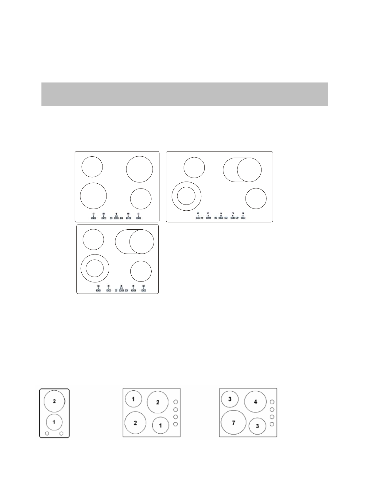
DESCRIPTION
HOT PLATES
1
23
1
3
2
1
4
1
1
4
1
Touch Control
1. Hi-lite heating element 145mm. 1200Watt
2. Hi-lite heating element 180mm. 1800Watt
3. Double circuit Hi-lite heating element 120/210mm. 750/2200Watt
4. Double circuit oval Hi-lite heating element 180/260mm. 750/2200Watt
3
Page 4
Knob Control
1. Radiant heating element 145mm. 1200Watt
2. Radiant heating element 180mm. 1700Watt
3. Hi-lite heating element 145mm. 1200Watt
4. Hi-lite heating element 180mm. 1800Watt
5. Double circuit Hi-lite heating element 120/210mm 750/2200Watt
6. Double circuit oval Hi-lite heating element 180/260mm 750/2200Watt
7 Hi-lite heating 210mm 2200Watt
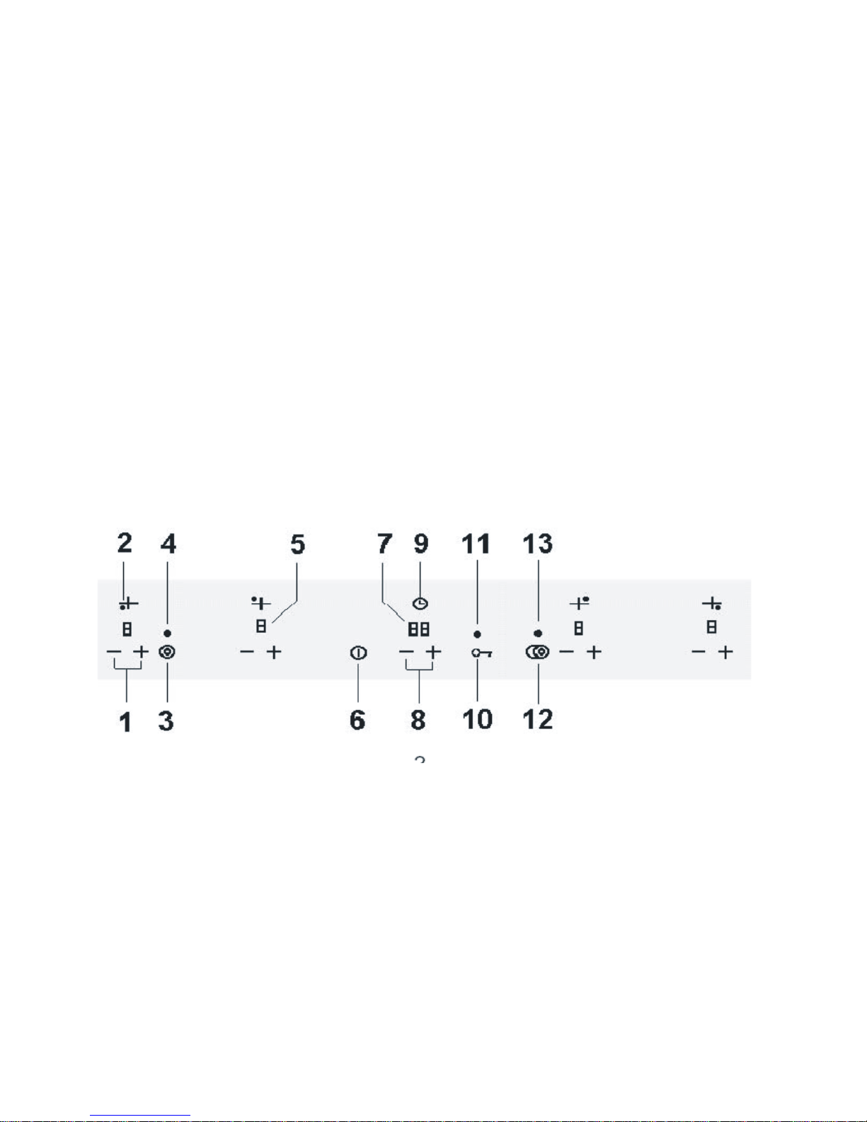
TOUCH CONTROL
1- Selection of cooking setting 8- Selection of timer setting
2- Cooking setting position 9- Timer position
3- Connection key front left 10- Locking of the cooking surface
connection and selection
4- Connection display front left 11- Locking display
5- Display of cooking setting 12- Connection key rear right
6- On/Off switch, emergency off switch 13- Connection display rear right
7- Display timer
4
Page 5

Using the Appliance
WARNING
All operations relative to installation and electric connection should be carried out by
qualified personnel in conformity with the regulations in force in your country.
The specific instructions are described in the booklet section for the installer
NOTICE
• Use only flat pans with a sufficiently thick base, equal to or not much larger than the hot plate selected (fig.1)
• The containers should not have rough bottoms in order to avoid scratching the heat surface of the top.
• Do not switch the electric plate on without the pan over the plate.
• Do not cook any food directly on the hot area. Avoid overflows of liquid and should they occur clean away
promptly.
• Turn off the plate few minutes before the cooking end.
USE
Model with knob control switches
Switching on
Set the power by rotating the knob, taking into consideration that the highest number corresponds with the
maximum power. If the hob is fitted with extended zones, the outer heating element can be switched on turning
the knob up to the end of rotation.
The pilot light is switched ON when at least one element is on. The pilot light is switched ON when the top
temperature at indicated spot is higher than 50
Model with touch control switches
Switching on
O
C.
5
Page 6

The control is switched on by pressing the On/Off key(key 6) for 1 second, causing a sound signal it will not turn
on while the key lock function (key 10) is active(indicated by Led11).
The heating element remain switched off (all the digits at 0) until a power level is selected. If this is not done
within 10 seconds the control switches off automatically.
Selecting the cooking level
With the control turned on, the first time that the (+) sensor (key1) is touched and heating element is turned on to
the selected level.
The (+) sensor raises the cooking level to a maximum of 9, and the (-) (key 1) sensor reduces the cooking level
to 0 (heating element switched off).
If a sensor is continuously pressed, the action involved is repeated every half second.
If we start with the (-) sensor the cooking level will be the highest (9).
Switching the double cooking area
The control(key 3) or (key 12) can be used to activate 2 heating elements with a double cooking area and one of
them with triple area, with 2 sensors to activate or cancel it. Each cooking area has an associated LED (Led 4
and 13). The selection of the heating element associated with the second cooking area is made in the factory
through the configuration software.
Touch the double area selector to select/deselect the double cooking area. If one heating-element has 1 double
and 1 triple areas the product will be:
st
1
touch: the double area is selected
nd
2
touch: the triple area is selected
rd
3
touch: double and triple areas are not selected.
When the double cooking area is selected the associated LED (Led 4 or 13) turns on, although its heating
element has not been activated.
Activating the heat-up function
When cooking level 9 is selected (this function can only be operated from this level) touching the (+)(key 1)
sensor, the decimal point on the display(5) blinks for 10 seconds, during which the desired power level must be
selected (between 1 and 8). After this time there is a sound signal, and the decimal point remains fixed,
indicating the heat-up function is ON. Should the selected level be 0 or 9, the heat-up function is cancelled.
With the heat-up function activated, by touching the (+) sensor the duration of this function extends to the new
power value selected; if the power is 9, the heat-up function is cancelled. When the heat-up function is finished,
there is a sound signal, the decimal point of the display goes out and the element remains at the chosen power
level.
Cancelling the heat-up function
Touch the (-) (key 1) sensor while the heat-up function is ON to cancel it. The cooking level goes down.
When the heat-up function is cancelled, there is a sound signal and the decimal point on the display goes out. A
blinking “H” will appear with the cooking level 0, when the temperature of the heating element reaches 65°C. It
appears fixed if the touch control is switched off.
Setting the Key lock function
Keep the Key Lock (Key 10) sensor pressed to activate/cancel the keyboard locking function. If the LED (11)
associated with the Key Lock sensor is on, the keyboard is locked.
The locking function can be activated when the cooking levels are activated or when the cook top is off.
If the cook top is on, The Key Lock function locks all the sensors except the On/Off (Key 6) general sensor and
the key lock sensor.
When the cook top is turned off, the Key Lock function blocks all the sensors, including the general On/Off
switch, except the key lock sensor.
Cancellation of the Key Lock function
If the keyboard is locked (the LED 11) associated with the Key Lock (Key 10) sensor is on, keep the Key Lock
sensor pressed for 1 second to cancel the locking function and the indicator light will go out.
Residual heat indicator
6
Page 7

While the temperature on the cook top surface is above 65°C, this condition will be shown in the associated
display, by means of an “H”.
If the cook top is switched off, residual heat is shown by a static “H” in the display. If the cook top is on, but the
power level is 0, the associated display will show alternately “H” and “0”.
To generate a temperature above 65°C a heating element has to be in operation for a certain time, which
depends on the selected power level. Once this time is passed, the residual heat warming will come into
operation when the element is switched off.
If the minimum time needed to exceed 65°C is over, the length of time the residual heat indicator remains in
operation is a function of the time the element has remained turned on at a certain power level.
Safety auto-power-off
If the power level is not changed for a present time, the element in question will automatically be turned off.
The maximum operating time of an element depends on the cooking level selected.
Power Level Max time ON (hours)
1 10
2 5
3 5
4 4
5 3
6 2
7 2
8 2
9 1
Thermal protection of the control panel
When the control panel detects an ambient temperature above 96°C it turns off the nearest element (selected by
software), and an “H” for residual heat shows in the associated display.
An element turned off by the thermal protection can only be re-activated when the temperature falls below 89°C.
This is a safety measure to protect your cooktop.
Timer operation
The timer is activated by pressing the (+) or (-) (Key 8) timer sensors. It can be set to any value between 1 and
99 minutes and can modifies at any moment.
To cancel the timer, select the <00> value using the (-) timer sensor or switch it of by pressing the (+) and (-)
timer sensors simultaneously.
The timer can be customised to suit the needs of the user by configuring the following options:
1. Increase of timer value (1 min. /5 min.)
2. Timed heating element (fixed/programmable)
3. Indication of timed heating element
4. Duration of the acoustic alarm (1min./indefinite)
5. Default initial timer value
6. Timer/Timer-Alarm mode
Increase of timer value
Pressing the (+) or (-) (Key 8) timer sensor for a sustained period will result in an automatic increase/decrease,
enabling the user to reach the desired timer value faster. The increase can be set to 1 minute or 5 minute
increases/decreases.
*1 minute increases:
After the tenth consecutive increase/decrease the timer value increases or decreases fasten
*5 minute increases:
After the fifth consecutive increase/decrease when the timer value reaches a multiple of 5, it increases or
decreases 5 by 5 units instead of 1 by 1.
Timed heating element
Any of the heating elements under the touch control system, either single or double, can be timed.
When the timed period is over, the timed heating-element (and if applicable the twin area as well)
7
Page 8

Switches itself off automatically. The timed heating element can be programmed as follow:
*Fixed heating element:
The timer setting always applies to the same heating element.
*Programmable heating element:
The user can decide which heating element to time. The selection of a new heating element cancels the
previous choice, thus the timer setting can only apply to one heating element at a time.
When we touch the keys (8) of the timer the first time, it will appear as “t” in each heating element display
awaiting your selection.
*We always have to select the heating element after we have pressed a key of the timer.
*If we do not select any heating element during 10sec., then the timer will switch off.
*After our heating element selection we do not indicate a time different then 00, in 10 sec. The timer will switch
off.
Indication of timed heating element
The touch control can indicate which heating element the timer is set up to control.
A flashing “t” appears over the timer heating element display (5) for 5 seconds ev ery 15 seconds or every time
the (+) or (-) timer sensors are pressed (Key 8).
This option is advisable when timed heating element is programmable, as it serves to remind the user which
heating element has been selected.
Duration of the acoustic alarm
Once the timer period has finished, an acoustic alarm sounds for a certain period <00> and flashes on the timer
displays (7). The duration of the acoustic alarm can be programmed.
*1 minute alarm:
The acoustic alarm stops after 1 minute. The timer displays continue to flash <00>. The user can switch off the
alarm at any moment, even during the first minute, by pressing any sensor of the touch control.
*Indefinite alarm:
The alarm continues to sound until the user switches it off by pressing any sensor of the touch control.
Default initial timer value
The timer is switched on by pressing the (+) or (-) timer sensor (Key 8). If the (-) sensor is pressed the initial
timer value will be 99 minutes, whereas with the (+) sensor, the initial timer value can be predetermined to any
value between 00 and 99 minutes.
Timer/Timer-Alarm mode
The timer has two different working modes:
*Timer mode: when the programmed period is over, the alarm is activated and the timed heating eleme nt
switches itself off automatically. If the timer is set in this mode, this is indicated by the fact that the decimal point
on the timer display is lit (7)
*Alarm mode: when the programmed period is over, the alarm is activated although the timed heating element is
not switched off automatically. If the timer is set in this mode, this is indicated by the fact that the decimal point
on the timer display is not lit (7).
The touch control enables the timer to be programmed for the following settings:
8
Page 9

1. Timer setting: Only allow the timer to work in timer mode.
2. Timer-alarm setting: Allow the timer to work in either timer mode or alarm mode. The working mode is
programmed by the user.
Configuration examples
The following examples detail the basic functioning of the timer combining the timed heating element
(fixed/programmable) and timer/timer-alarm settings. Any combination of the 4 remaining options (see below)
Can be added to these examples.
Increase of timer value (1 min. /5min.)
Indication of timed heating element. Duration of the acoustic alarm (1min./indefinite) Default initial timer value.
These options permit the touch control timer to be customised to meet the individual requirements of the user.
Example#1: Fixed timed heating element + timer setting
The timer always work in timer mode, regulating the length of timed heating element is switched on. Once the
programmed period is over, the timed heating element switches itself off automatically. The corresponding
display (5) also switches off or shows an “H” to indicate residual and the timer alarm is activated.
Example#2: Fixed timed heating element + timer alarm setting
The timer functions in either timer mode or alarm mode.
Timer mode: the programmed value determines the time during which the timed heating element is activated.
Once the programmed period is passed, the fixed timed heating element switches itself off automatically. The
corresponding display (5) also switches off or shows an “H” to indi cate residual heat and the timer alarm is
activated. To select this mode, before activating the timer (the timer display (7) should be switched off) select a
power setting (1) other then 0 for the fixed timed heating element, then set the timer value. When this mode is
selected, the decimal point on the timer display is activated (5).
Alarm mode: the programmed value determines the time which must pass before the alarm is activated. Once
the programmed time is over, the time alarm is activated although the heating element does not switch
Itself off automatically. To select his mode, before activating the timer (the timer display (7) should be switched
off) select the 0 power setting for the timed heating element, then set the timer value. When this mode is
selected, the decimal point on the timer display will be switched off. Once the alarm mode has been selected,
you can switch on the timed heating element.
Programmable timed heating element + timer setting
The timer always functions in timer mode, regulating the time during which the timed heating element
programmed by the user is activated. The activation of this setting is indicated by the presence of a decimal
point on the timer display (7). To select the timed heating element, when the timer is activated a “t” appears on
the displays (5) of each one of the heating elements. The user has 10 seconds to select the heating element he
or she wishes to time. To select a heating element simply press either the (+) or (-) (Key 1) sensor of he chosen
heating element.
Once the heating element has been selected, the “t” on the displays (5) will disappear, enabling the user to
select the power settings and timer values required. Once the programmed time is over, the timed heating
element will automatically switch itself off.
The corresponding display (5) also switches off or shows an “H” to indicate resid ual heat and the timer alarm is
activated.
If the user does not select a heating element, the process is cancelled, the “t” disappears from the display s (5 )
and the timer is deactivated. The selection process is reinitiated each time the timer is activated.
Programmable timed heating element + timer alarm setting
The timer can function in either timer mode or in alarm mode. When the timer is activated a “t” appears on the
displays (5) of each of the heating elements. The user has 10 seconds to select the heating he or she wi shes to
time. To select a heating element, simply press either (+) or (-) (1) sensor of the chosen heating element.
Timer mode: once the heating element has been selected, the “t” on the displays (5) will disappear, enabling the
user to select the power settings and timer values required. The activation of this setting is indicated by the
presence of the decimal point on the timer display (7). Once the programmed time has passed, the timed
9
Page 10

heating element will switch itself off automatically. The corresponding display (5) also switches off or shows an
“H” to indicate residual heat and the timer alarm is activated.
Alarm mode: if no heating element is selected, the “t” on the displays (5) disappears, enabling the user to set the
timer value. After the programmed period has passed, the alarm will be activated although no heating element
will switch itself off automatically. When this mode is selected, the decimal point on the timer display
will be switched off.
General switch off
The cook top can always be switched off; regardless of the mode of operation it is, by touching the On/Off
sensor (Key 6) for 1 second. On switching off, there is a beep signal and the displays are turned off, unless there
has to be an “H” for residual heat on any display.
Special Notes
If the Keys for (+) or (-) (Key1) of an element are touched together, the element turns off (display at 0). If the
keys touched simultaneously are not of the same element the keyboard is locked and no operation i s allo wed.
The On/Off function prevails if 2 keys are touched at the same time, but only to turn off.
If all the cooking levels are at position 0, the control will turn off automatically after 10 sec. If a sensor is pressed
for more than 10 sec., the control will automatically turn off and a “beep” will sound every
30 sec., while the sensor is pressed.
Cleaning
Remove leftover and grease or spillage from the cooking surface with the special scraper (fig.3) (optional).
Then clean the heating area thoroughly with a paper towel and ceramic cleaning products for the correct care of
your appliance. Never use abrasive sponge or irritating chemical detergents such as over spray or spot
removers.
10
Page 11

11
Page 12

Installation Instructions
WARNING
The operations indicated below must be followed by qualified personnel,
in conformity with the regulations in force.
The supplier refuses all responsibility for damages to person or property,
resulting from the failure to comply with such provisions.
INSTALLATION
All units are 230/240 power and 60hz
The appliance is designed to be embedded into heat resistant pieces of furniture or kitchen cabinetry.
Make the hole in the top of the piece of furniture with the dimension indicated in fig. 4 at a distance of at least
50mm from the appliance border to the adjacent walls.
Adhesive washer “S” along the border of the top bottom (fig.5)
Stabilise it with the fastening hooks “C” (fig.6)
ELECTRICAL CONNECTIONS (FIG.7)
Before carrying out electrical connection be sure that the characteristics of the electrical system meet the
specifications located at the bottom of the cooktop and the electrical system is provided with effective ground in
compliance with the regulations and provision of the law in your country.
The ground is required in all circumstances.
If you wish a direct connection to the line, it is necessary to use a single pole switch, with a minimum opening
between the contacts of 3 mm. suitable for the purpose and in conformity with the rules in your country (the
yellow/green ground cable should not be interrupted by the switch).
ATTENTION
Should a built-in oven or any other appliance producing heat be fitted directly
under a glass ceramic cook-top with touch control, it is recommended to insulate
the hob with a separator which is usually a piece of temperature resistant
timber. The operating temperature of the cooktop must be below 60°C.
Disregard of this precaution could cause the incorrect operation of the touch
control system of the cooktop and effect the product warranty provisions.
12
Page 13

DIMENSIONS AND CUT-OUTS
30CM CERAMIC HOB (12”)
1700 /
1200
60CM CERAMIC HOB (24”)
1800 /
1200
75CM CERAMIC HOB (30”)
Hob: W 288mm D 510mm
W 11 Inches 20 Inches
Cut-out W 270mm D490mm
W10.5 Inches D19 Inches
Hob: W 600mm D 510mm
W 23.5 Inches D 20 Inches
Cut-out: W 560mm D 490mm
W 22 Inches D 19 Inches
90CM CERAMIC HOB (36”)
1200 /
750/2200
1200 /
750/2200
Hob: W 770mm D 510mm
W 30 Inches D 20 Inches
Cut-out: W750mm D 490mm
W29.5 Inches D 19 Inches
13
Page 14

Hob: W 900mm D510mm
1200 /
W 35.5 Inches D20 Inches
750/2200
Cut-out W 860mm D 490mm
1200 /
W 34 Inches D 19 Inches
750/2200
Warranty
Porter&Charles products are designed and built to the highest standards. We expect your appliances
to provide many years of trouble free enjoyment. In the event of an appliance requiring attention, each
appliance is covered by a 2 year warranty from the date of purchase.
Refer to warranty policy for complete terms and conditions.
Coverage is for costs of parts and labor for appliances in capital cities & metropolitan areas. We
reserve the right to charge directly for handling expenses outside the metropolitan region.
Porter&Charles products are supported by a national service support system.
Call our customer service department for attention.
Please retain your Porter&Charles invoice to quote should you require service assistance. This
will identify your product for our priority service back-up. Please attach your invoice to this
manual for easy future reference.
PORTER & CHARLES INCORPORATED
Suite 811, 99 Bronte Road,
Oakville, Ontario,
Canada L6L3B9
Telephone: 1-866.699-4973
Telephone: 905-829.8389
Facsimile: 905-829.8409
For Service & Spares:
EURO-PARTS
1-800.678-8352
Important: Please record details of your purchase below and mail or fax to:
------------------------------------------------------------------------cut along line -----------------------------------------------------------------------
14
Page 15

Porter&Charles
Name:____________________________ Tel no ______________________________________
Address: _______________________________________________________________________
City: ______________________ State:_______________ Zip Code: _______ ________
Where purchased: _________________________ Purchase date ;___________________
Items
purchased:_____________________________________________________________________
Serial No. (s): ___________________________________________________________________
15
Page 16

Porter & Charles
16
 Loading...