

Porter-Cable PXCML224VW Instruction Manual
PXCML224VW
www.portercable.com
OPERATING INSTRUCTIONS, SERVICE
CENTERS AND WARRANTY POLICY.
READ THESE INSTRUCTIONS
BEFORE USING THE PRODUCT.
INSTRUCTIONS DE FONCTIONNEMENT,
CENTRES DE SERVICES ET POLITIQUE DE
GARANTIE.
LIRE LES
INSTRUCTIONS AVANT D'UTILISER LE
PRODUIT.
INSTRUCTIVO DE OPERACIÓN, CENTROS
DE SERVICIO Y PÓLIZA DE GARANTÍA.
LÉASE ESTE INSTRUCTIVO
ANTES DE USAR EL PRODUCTO.
Français : Page 27
Español: Página 54
Air Compressor
Compresor de aire
Compresseur d’air
Instruction manual
Manuel d'instructions
Manual de instrucciones
2- ENG
GENERAL SAFETY RULES
This manual contains information that is important for you to know and understand.
This information relates to protecting YOUR SAFETY and PREVENTING
EQUIPMENT PROBLEMS. To help you recognize this information, we use the
symbols below. Please read the manual and pay attention to these symbols.
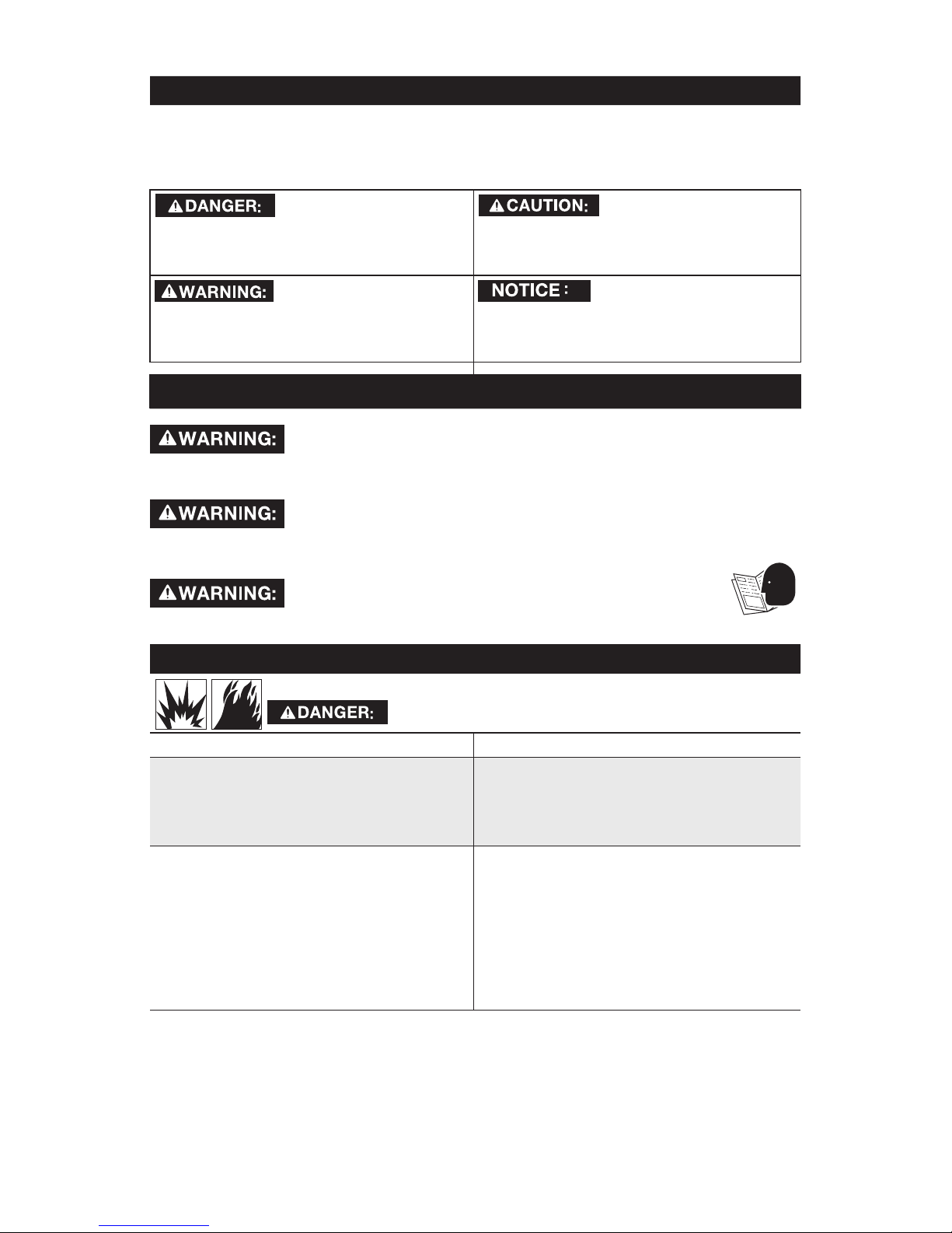
Indicates an imminently
hazardous situation which, if not
avoided, will result in death or serious
injury.
Indicates a potentially
hazardous situation which, if not
avoided, may result in minor or
moderate injury.
Indicates a potentially
hazardous situation which, if not
avoided, could result in death or
serious injury.
Indicates a practice
not related to personal injury which,
if not avoided, may result in property
damage.
IMPORTANT SAFETY INSTRUCTIONS
This product contains chemicals known to the State of California
to cause cancer, and birth defects or other reproductive harm. Wash hands after
handling.
Some dust contains chemicals known to the State of California
to cause cancer, birth defects or other reproductive harm such as asbestos and
lead in lead based paint.
To reduce the risk of injury, read the instruction manual.
SAVE THESE INSTRUCTIONS
HAZARD
RISK OF EXPLOSION OR FIRE
WHAT CAN HAPPEN HOW TO PREVENT IT
• It is normal for electrical
contacts within the motor and
pressure switch to spark.
• Always operate the compressor
in a well ventilated area free
of combustible materials,
gasoline, or solvent vapors.
• If electrical sparks from
compressor come into contact
with flammable vapors, they may
ignite, causing fire or explosion.
• If spraying flammable materials,
locate compressor at least
20' (6.1m) away from spray
area. An additional length of
air hose may be required.
• Store flammable materials
in a secure location away
from compressor.
3 - ENG
• Restricting any of the compressor
ventilation openings will
cause serious overheating
and could cause fire.
• Never place objects against
or on top of compressor.
• Operate compressor in an open
area at least 12" (30.5 cm) away
from any wall or obstruction that
would restrict the flow of fresh
air to the ventilation openings.
• Operate compressor in a
clean, dry well ventilated area.
Do not operate unit in any
confined area. Store indoors.
• Unattended operation of this product could result in personal injury
or property damage. To reduce the
risk of fire, do not allow the compressor to operate unattended.
• Always remain in attendance with
the product when it is operating.
• Always turn off and unplug
unit when not in use.
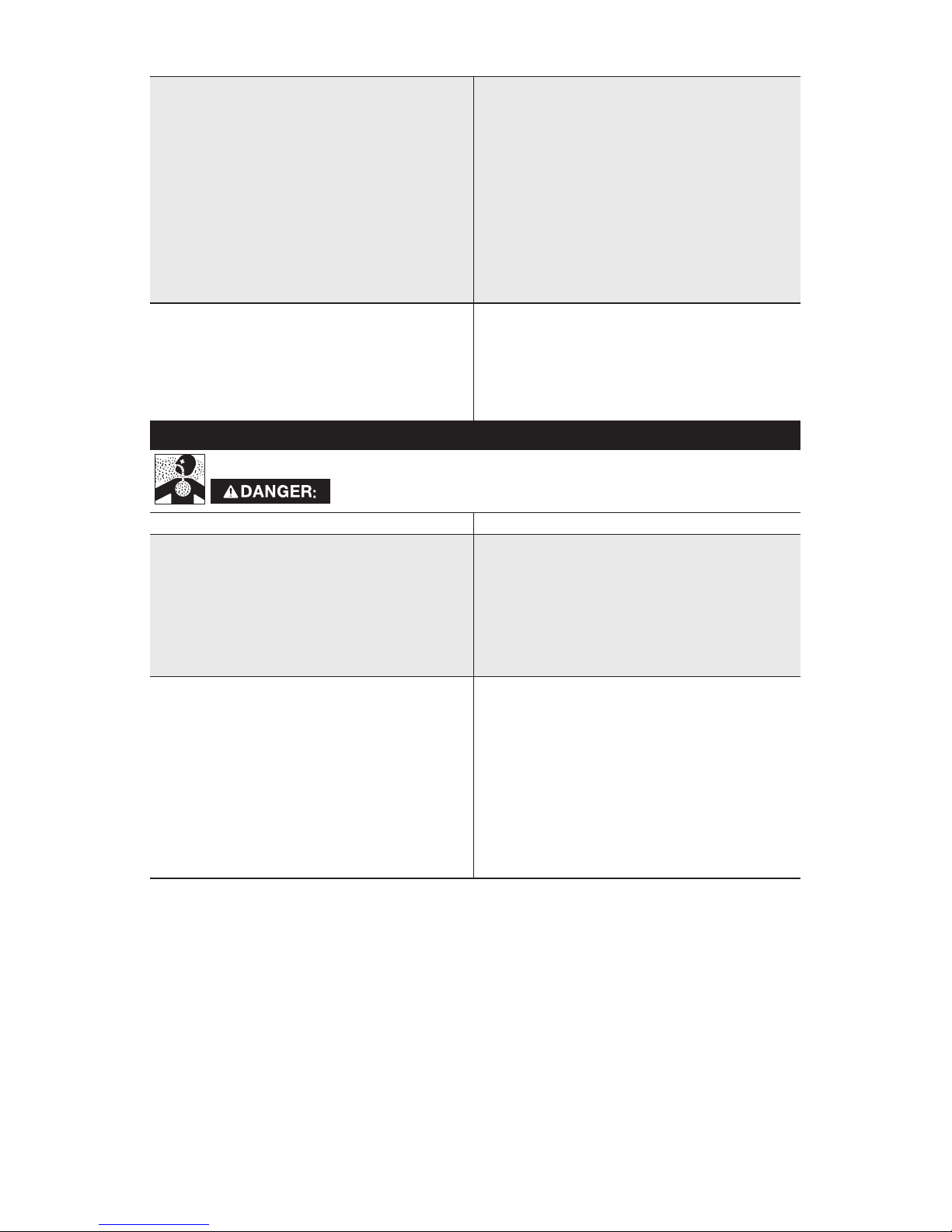
HAZARD
RISK TO BREATHING (ASPHYXIATION)
WHAT CAN HAPPEN HOW TO PREVENT IT
• The compressed air directly from
your compressor is not safe for
breathing. The air stream may
contain carbon monoxide, toxic
vapors, or solid particles from the air
tank. Breathing these contaminants
can cause serious injury or death.
• Never use air obtained directly
from the compressor to supply
air for human consumption. The
compressor is not equipped with
suitable filters and in-line safety
equipment for human consumption.
• Exposure to chemicals in dust
created by power sanding,
sawing, grinding, drilling,
and other construction
activities may be harmful.
• Sprayed materials such as paint,
paint solvents, paint remover,
insecticides, weed killers, may
contain harmful vapors and poisons.
• Work in an area with good cross
ventilation. Read and follow
the safety instructions provided
on the label or safety data
sheets for the materials you are
spraying. Always use certified
safety equipment: NIOSH/OSHA
respiratory protection or properly
fit ting face mask designed for use
with your specific application.

4- ENG
HAZARD
RISK OF BURSTING
Air Tank: On February 26, 2002, the U.S. Consumer Product Safety Commission
published Release # 02-108 concerning air compressor tank safety:
Air compressor receiver tanks do not have an infinite life. Tank life is dependent
upon several factors, some of which include operating conditions, ambient
conditions, proper installations, field modifications, and the level of maintenance.
The exact effect of these factors on air receiver life is difficult to predict.
If proper maintenance procedures are not followed, internal corrosion to the
inner wall of the air receiver tank can cause the air tank to unexpectedly rupture
allowing pressurized air to suddenly and forcefully escape, posing risk of injury to
consumers.
Your compressor air tank must be removed from service by the end of the year
shown on your tank warning label.
The following conditions could lead to a weakening of the air tank, and result in a
violent air tank explosion:
WHAT CAN HAPPEN HOW TO PREVENT IT
• Failure to properly drain condensed
water from air tank, causing rust
and thinning of the steel air tank.
• Drain air tank daily or after each use.
If air tank develops a leak, replace
it immediately with a new air tank
or replace the entire compressor.
• Modifications or attempted
repairs to the air tank.
• Never drill into, weld, or make any
modifications to the air tank or its
attachments. Never attempt to
repair a damaged or leaking air
tank. Replace with a new air tank.
• Unauthorized modifications
to the safety valve or any
other components which
control air tank pressure.
• The air tank is designed to withstand
specific operating pressures.
Never make adjustments or
parts substitutions to alter the
factory set operating pressures.
Attachments & accessories:
• Exceeding the pressure rating of air tools, spray guns, air
operated accessories, tires,
and other inflatables can cause
them to explode or fly apart, and
could result in serious injury.
• Follow the equipment manufacturers
recommendation and never exceed
the maximum allowable pressure
rating of attachments. Never use
compressor to inflate small low
pressure objects such as children’s
toys, footballs, basketballs, etc.

5 - ENG
Tires:
• Over inflation of tires could result in
serious injury and property damage.
• Use a tire pressure gauge to check
the tires pressure before each use
and while inflating tires; see the tire
sidewall for the correct tire pressure.
NOTE: Air tanks, compressors and
similar equipment used to inflate
tires can fill small tires very rapidly.
Adjust pressure regulator on air
supply to no more than the rating
of the tire pressure. Add air in small
increments and frequently use the
tire gauge to prevent over inflation.
HAZARD
RISK OF ELECTRICAL SHOCK
WHAT CAN HAPPEN HOW TO PREVENT IT
• Your compressor is powered by
electricity. Like any other electrically
powered device, if it is not used
properly it may cause electric shock.
• Never operate the compressor
outdoors when it is raining
or in wet conditions.
• Never operate compressor
with protective covers
removed or damaged.
• Repairs attempted by unqualified
personnel can result in serious
injury or death by electrocution.
• Any electrical wiring or repairs
required on this product should be
performed by authorized service
center personnel in accordance with
national and local electrical codes.
• Electrical Grounding: Failure to
provide adequate grounding to this
product could result in serious injury
or death from electrocution. Refer to
Grounding Instructions paragraph
in the Installation section.
• Make certain that the electrical
circuit to which the compressor
is connected provides proper
electrical grounding, correct voltage
and adequate fuse protection.

6- ENG
HAZARD
RISK FROM FLYING OBJECTS
WHAT CAN HAPPEN HOW TO PREVENT IT
• The compressed air stream can
cause soft tissue damage to
exposed skin and can propel dirt,
chips, loose particles, and small
objects at high speed, resulting in
property damage or personal injury.
• Always wear certified safety
equipment: ANSI Z87.1 eye
protection (CAN/CSA Z94.3)
with side shields when
using the compressor.
• Never point any nozzle or sprayer
toward any part of the body or
at other people or animals.
• Always turn the compressor
off and bleed pressure from
the air hose and air tank before
attempting maintenance,
attaching tools or accessories.
HAZARD
RISK OF HOT SURFACES
WHAT CAN HAPPEN HOW TO PREVENT IT
• Touching exposed metal such
as the compressor head, engine
head, engine exhaust or outlet
tubes, can result in serious burns.
• Never touch any exposed metal
parts on compressor during or
immediately after operation.
Compressor will remain hot for
several minutes after operation.
• Do not reach around protective
shrouds or attempt maintenance
until unit has been allowed to cool.
HAZARD
RISK FROM MOVING PARTS
WHAT CAN HAPPEN HOW TO PREVENT IT
• Moving parts such as the pulley,
flywheel, and belt can cause
serious injury if they come into
contact with you or your clothing.
• Never operate the compressor
with guards or covers which
are damaged or removed.
• Keep your hair, clothing, and
gloves away from moving parts.
Loose clothes, jewelry, or long hair
can be caught in moving parts.
• Air vents may cover moving parts
and should be avoided as well.
• Attempting to operate compressor
with damaged or missing parts or
attempting to repair compressor
with protective shrouds removed
can expose you to moving parts
and can result in serious injury.
• Any repairs required on this product
should be performed by authorized
service center personnel.
7 - ENG
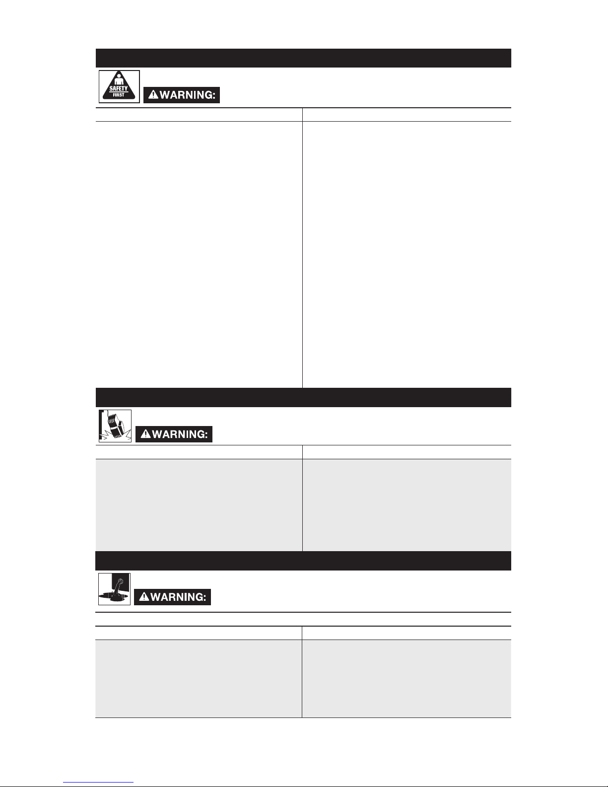
HAZARD
RISK OF UNSAFE OPERATION
WHAT CAN HAPPEN HOW TO PREVENT IT
• Unsafe op er a tion of your
compressor could lead to se ri ous
in ju ry or death to you or others.
• Review and understand all
instructions and warnings
in this manual.
• Be come fa mil iar with the op eration
and con trols of the air compressor.
• Keep operating area clear of all
persons, pets, and obstacles.
• Keep chil dren away from the
air compressor at all times.
• Do not operate the product
when fatigued or under the
influence of alcohol or drugs.
Stay alert at all times.
• Never defeat the safety
features of this prod uct.
• Equip area of operation
with a fire extinguisher.
• Do not op er ate machine
with missing, broken, or
un au tho rized parts.
HAZARD
RISK OF FALLING
WHAT CAN HAPPEN HOW TO PREVENT IT
• A portable compressor can fall
from a table, workbench, or roof
causing damage to the compressor
and could result in serious injury
or death to the operator.
• Always operate compressor in a
stable secure position to prevent
accidental movement of the unit.
Never operate compressor on a
roof or other elevated position. Use
additional air hose to reach high
locations.
HAZARD
WHAT CAN HAPPEN HOW TO PREVENT IT
• Oil can leak or spill and could result
in fire or a breathing hazard. Spilled
oil may cause a slip and fall. Oil
leaks will damage carpet, paint or
other surfaces in vehicles or trailers.
• Always place compressor on a
protective mat when transporting to
protect against damage to vehicle
from leaks. Remove compressor
from vehicle immediately upon
arrival at your destination.
RISK OF SERIOUS INJURY OR PROPERTY DAMAGE
WHEN TRANSPORTING COMPRESSOR
8- ENG
HAZARD
RISK OF INJURY FROM LIFTING
WHAT CAN HAPPEN HOW TO PREVENT IT
• Serious injury can result
from attempting to lift
too heavy an object.
• The compressor is too heavy to be
lifted by one person. Obtain assistance from others before lifting.
RISK FROM NOISE
WHAT CAN HAPPEN HOW TO PREVENT IT
• Under some conditions and duration
of use, noise from this product
may contribute to hearing loss.
• Always wear certified safety
equipment: ANSI S12.6
(S3.19) hearing protection.
SAVE THESE INSTRUCTIONS
FOR FUTURE USE
SPECIFICATION CHART
Model No. PXCML224VW
Running Horsepower 1.5 *
Bore 1.89" (48.0 mm)
Stroke 1.5" (38.0 mm)
Voltage 120
Hz-Single Phase 60
Minimum Branch Circuit Requirement 15 amps
Fuse Type Time Delay
Air Tank Capacity (Gallon) 24 (90.8 liters)
Maximum Air Pressure 135 PSI
Approximate Cut-in Pressure 105 PSIG
Approximate Cut-out Pressure 135 PSIG
SCFM @ 40 PSIG 4.5 *
SCFM @ 90 PSIG 4.0 *
* Tested per ISO 1217
Refer to Glossary for abbreviations.
GLOSSARY
Air Filter
Porous element contained within a
metal or plastic housing attached to
the compressor cylinder head which
removes impurities from the intake air of
the compressor.
Air Tank
Cylindrical component which contains
the compressed air.
Check Valve
Device that prevents compressed air
from flowing back from the air tank to
the compressor pump.
Cut-In Pressure
The low pressure at which the motor will
automatically restart.
Cut-Off Pressure
The high pressure at which the motor
will automatically shut off.
Electric Motor
Device which provides the rotational force
necessary to operate the compressor pump.

9 - ENG
DUTY CYCLE
This air compressor pump is capable of running continuously. However, to prolong
the life of your air compressor, it is recommended that a 50% average duty cycle be
maintained; that is, the air compressor pump should not run more than 30 minutes in
any given hour.
ACCESSORIES
Accessories for this unit are available at the store the unit was purchased.
The use of any other accessory not recommended for use with this tool could
be hazardous. Use only accessories rated equal to or higher than the rating of
the air compressor.
NPT (National Pipe Thread)
A seal thread tape must be used to
provide a leak-free seal on pipe threaded
connections.
Pressure Regulator Knob
Regulates the outgoing pressure from
the air outlet to the tool. It is possible to
increase or decrease the pressure at the
outlet by adjusting this control knob.
Pressure Switch
Automatically controls the on/off
cycling of the compressor. It stops the
compressor when the cut-off pressure
in the tank is reached and starts the
compressor when the air pressure drops
below the cut-in pressure.The pressure
switch will not automatically start and
control the compressor unless the
manual AUTO/Off Switch is in the
AUTO position.
PSI (Pounds Per Square Inch)
Measurement of the pressure exerted
by the force of the air. The actual PSI is
measured by a pressure gauge on the
compressor.
Pump
Produces the compressed air with a
reciprocating piston contained within the
cylinder.
Regulator Pressure Gauge
Displays the current line pressure. Line
pressure is adjusted by rotating the
pressure regulator knob.
Pressure Relief Valve
Prevents air pressure in the air tank from
rising over a predetermined limit.
SCFM (Standard Cubic Feet Per Minute)
A unit of measure of air delivery.
Tank Pressure Gauge
Indicates the pressure in the air tank.
Thermal Overload Switch
Automatically shuts off the compressor
if the temperature of the electric motor
exceeds a predetermined limit.
10- ENG
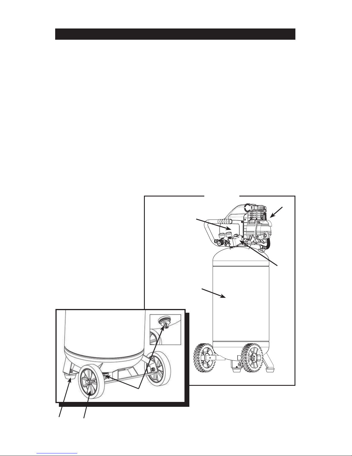
OVERVIEW
The basic components of the air compressor are the electric motor, pump,
pressure switch, and tank. (Figure 1)
The Electric Motor (A) powers the pump. The electric motor is equipped with
an overload protector and an automatic reset. If the motor becomes overheated,
the overload protector will shut it down to prevent damage to the motor.
The motor must be allowed to cool down before restarting. To reset the motor
overload toggle/turn the pressure switch AUTO/OFF lever to the OFF position
and unplug the unit from the power outlet. Allow 10 minutes (minimum) for motor
overload cut-out to cool and reset. Unit can then be plugged in and re-started.
The Pump (B) compresses the air and discharges it into the tank.
The Tank (C) stores the compressed air.
The Pressure Switch (D) shuts down the motor when the air pressure in the tank
reaches the cut–out pressure. As compressed air is used and the pressure level
in the tank drops to the cut–in pressure, the pressure switch restarts the motor
automatically, without warning, and the pump resumes compressing air.
Drain Valve (E) Condensation will accumulate in the tank. To prevent corrosion
of the tank from the inside, this moisture must be drained at the end of every
workday.
8" Wheel (2) (F)
Rubber Foot (2) (G)
C
A
B
Figure 1
D
E
G
F
11 - ENG
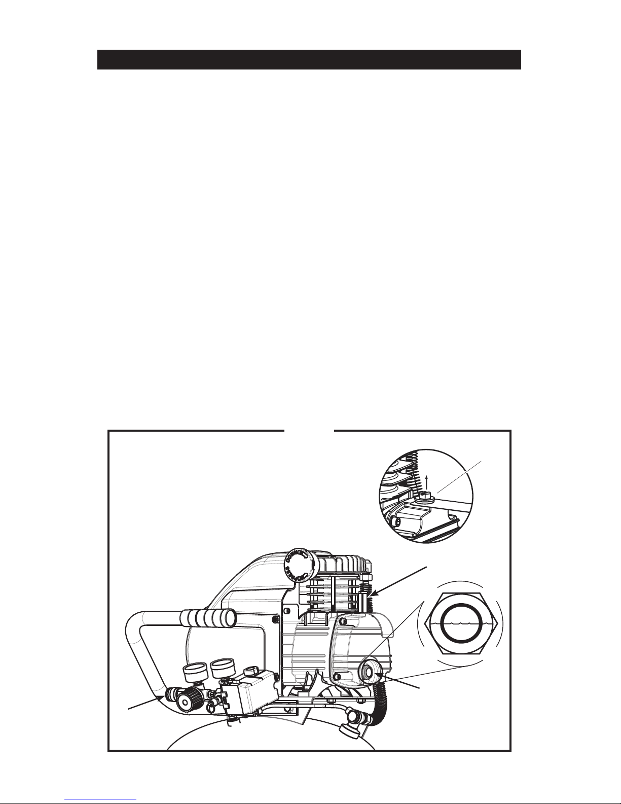
ASSEMBLY
ASSEMBLING THE COMPRESSOR (Figure 2)
1. Unpack the air compressor. Inspect the unit for damage. If the unit has been
damaged in transit, contact the carrier and complete a damage claim.
Do this immediately because there are time limitations to damage claims.
2. Check the compressor’s serial label to ensure that you have received the model
ordered, and that it has the required pressure rating for its intended use.
3. Locate the compressor according to the following guidelines:
a. Position the compressor near a grounded electrical outlet.
b. The compressor must be at least 12 inches (31 cm) from any wall or
obstruction, in a clean, well-ventilated area, to ensure sufcient air ow and
cooling.
c. In cold climates, store portable compressors in a heated building when
not in use. This will reduce problems with motor starting and freezing of
water condensation.
d. Remove the compressor from the carton and place it on the oor or a hard,
level surface. The compressor must be level to ensure proper drainage of
the moisture in the tank.
4. Remove the plug (A) from the oil ll port. Fill the compressor pump with high
quality air compressor oil at slow intervals until the oil reaches the center of the
red circle on the oil sight glass (B). Install the provided oil breather cap (C)
into the oil ll port.
5. Connect an air hose to the quick connector (D).
D
Figure 2
B
C
A
12- ENG
ELECTRICAL POWER REQUIREMENTS
ELECTRICAL WIRING
Refer to the air compressor’s serial label for the unit’s voltage and amperage
requirements.
EXTENSION CORDS
NOTE: Avoid use of extension cords.
For optimum performance, plug the compressor power cord directly into a
grounded wall socket. Do not use an extension cord unless absolutely necessary.
Instead, use a longer air hose to reach the area where the air is needed.
If use of an extension cord cannot be avoided, the cord should be no longer than
50 feet and be a minimum wire size of 12 gauge (AWG). Do not use a 16 or 14
gauge extension cord.
Use only a 3-wire extension cord that has a 3-blade grounding plug, and a 3-slot
receptacle that will accept the plug on the product. Make sure your extension
cord is in good condition. An undersized cord will cause a drop in line voltage,
resulting in loss of power and overheating. The smaller the gauge number, the
heavier the cord.
GROUNDING INSTRUCTIONS
This product must be grounded. In the event of an electrical short circuit,
grounding reduces the risk of electric shock by providing an escape wire for the
electric current.
This product is equipped with a cord having a grounding wire with an appropriate
grounding plug. The plug must be plugged into an outlet that is properly installed
and grounded in accordance with all local codes and ordinance is needed.
Improper installation of the grounding plug can result in
a risk of electric shock. If repair or replacement of the
cord or plug is necessary, do not connect the grounding wire to either
flat blade terminal. The wire insulation having an outer surface that is
green with or without yellow stripes is the grounding wire.
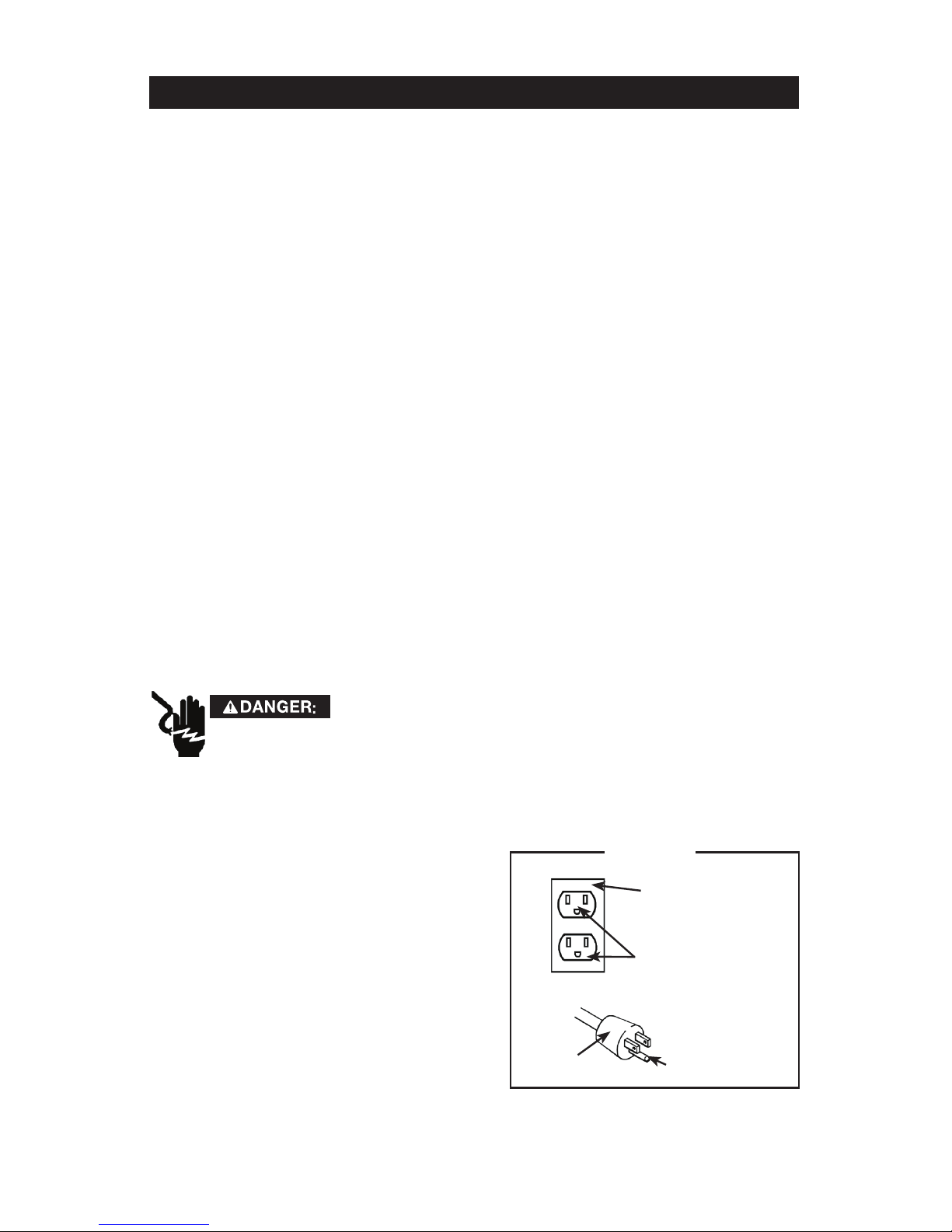
This product is for use on a nominal 120 volt circuit. A cord with a grounding
plug, as shown here, shall be used.
Make sure that the product is connected
to an outlet having the same configuration
as the plug (Figure 3). No adapter should
be used with this product.
Check with a licensed electrician if the
grounding instructions are not completely
understood, or if in doubt as to whether
the product is properly grounded. Do not
modify the plug provided; if it will not fit
the outlet, have the proper outlet installed
by a licensed electrician.
Figure 3
Grounded Outlet
Box
Grounded Outlet
Plug
Grounding Pin
120 VOLTS
13 - ENG
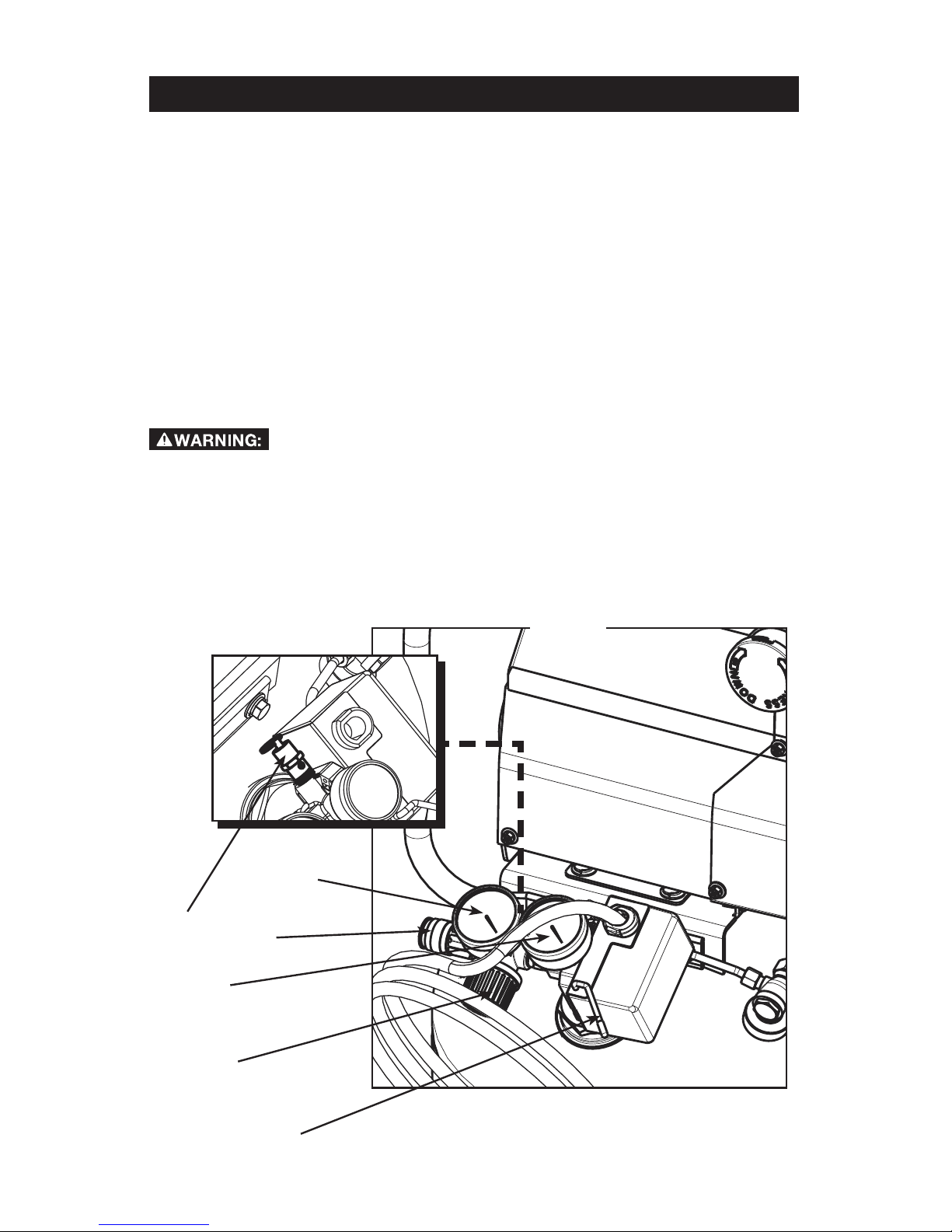
OPERATING INSTRUCTIONS
COMPRESSOR CONTROLS (Figure 4)
Pressure Switch (A): This switch turns on the compressor. It is operated manually,
but when in the AUTO position, it allows the compressor to start up or shut down
automatically, without warning, upon air demand. ALWAYS set this switch to OFF
when the compressor is not being used, and before unplugging the compressor.
Pressure Relief Valve (B): If the pressure switch does not shut down the motor
when pressure reaches the preset level, this valve will pop open automatically to
prevent over pressurization. To operate manually, pull the ring on the valve to relieve
air pressure in the tank.
Tank Pressure Gauge (C): This gauge measures the pressure level of the air stored
in the tank. It is not adjustable by the operator, and does not indicate line pressure.
Air Pressure Regulator (D): This air pressure regulator enables you to adjust line
pressure to the tool you are using.
Never exceed the maximum working pressure of the tool. Turn the knob clockwise
to increase pressure, and counterclockwise to decrease pressure.
Regulated pressure gauge (E): This gauge measures the regulated outlet
pressure.
Quick connector (F): Connect air hose to this outlet.
C
D
E
A
F
B
Figure 4
14- ENG
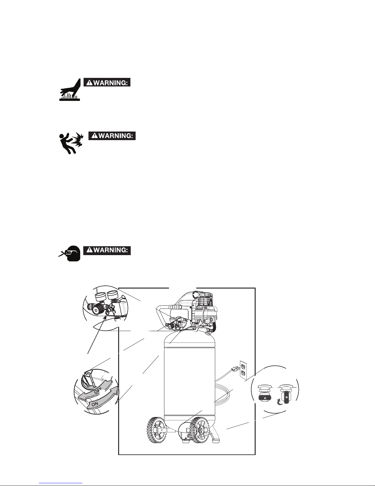
DAILY STARTUP (Figure 5)
1. Check the oil level in the pump (see "Checking the Oil" in maintenance section).
2. Turn the pressure switch to the OFF position (A).
3. Close the tank drain valve (B).
4. Plug in the power cord (C).
High temperatures are generated by the electric motor
and the pump. To prevent burns or other injuries, DO NOT
touch the compressor while it is running. Allow it to cool
before handling or servicing.
Keep children away from the compressor at all times.
5. Turn the pressure switch to the AUTO position (D).
When adjusting from a higher to a lower pressure, turn
the knob counterclockwise past the desired setting,
then turn clockwise to reach the desired pressure.
Do not exceed operating pressure of the tool or accessory being used.
6. Adjust the air pressure regulator to the working pressure of the tool being used.
SHUTDOWN (Figure 5)
1. Turn the pressure switch to the OFF position (A).
2. Unplug the power cord (C).
3. Reduce pressure in the tank through the outlet hose. You can also pull the
relief valve ring (E) and keep it open to relieve pressure in the tank.
4. Drain water from air tank by opening drain valve (counterclockwise) on bottom
of tank (B).
Escaping air and moisture can propel debris that may
cause eye injury. Wear safety goggles when opening drain
valve.
Figure 5
E
D
A
OPEN
CLOSE
B
C

15 - ENG
MAINTENANCE
To avoid personal injury, always shut off and unplug the compressor and relieve all
air pressure from the system before performing any service on the air compressor.
Regular maintenance will ensure trouble free operation. Your electric powered air
compressor represents high quality engineering and construction; however, even
high quality machinery requires periodic maintenance. The items listed below
should be inspected on a regular basis.
CHECKING THE OIL
Check the level of oil in the pump with the sight glass. The pump oil level must be
between A and B (See Figure 7). Do not overfill or underfill.
CHANGING THE OIL (Figure 6)
1. Remove the oil cap (1) on the pump.
2. Remove the sight glass (2) with a box-end wrench or socket. Drain the oil into
a suitable container and dispose of properly. The compressor may need to be
tipped slightly towards the drain hole to allow all of the oil to drain.
3. Reattach the sight glass (2). Be sure the gasket is between the sight glass and
the pump crankcase. Tighten the sight glass until the gasket is seated against
the pump crankcase and then tighten sight glass another 3/4 of a turn.
4. Refill the compressor with high quality compressor oil at slow intervals until the
oil reaches the center of the red circle in the sight glass (2). Replace oil cap (1)
on the pump.
Figure 6
Figure 7
1
2
B
A
16- ENG
Perform the following maintenance at the intervals indicated
below.
Operate the pressure relief valve ..........Daily
Drain tank .............................Daily
SERVICE INTERVAL
DRAINING THE TANK
Condensation will accumulate in the tank. To prevent
corrosion of the tank from the inside, this moisture
must be drained at the end of every workday. Be sure to wear protective
eyewear. Relieve the air pressure in the system and open the drain valve
on the bottom of the tank and tilt tank to drain.
NOTE: In cold climates, drain the tank after each use to reduce problems with
freezing of water condensation.
CHECKING THE RELIEF VALVE
Pull the relief valve daily to ensure that it is operating properly and to clear the valve
of any possible obstructions.
Check that all connections are tight. A small leak in any of the hoses, transfer
tubes, or pipe connections will substantially reduce the performance of your air
compressor.
TESTING FOR LEAKS
If you suspect a leak, spray a small amount of soapy water around the area of the
suspected leak with a spray bottle. If bubbles appear, repair or replace the faulty
component. Do not overtighten any connections.
STORAGE
Before storing the compressor for a prolonged period, use an air blow gun to clean
all dust and debris from the compressor. Disconnect the power cord and coil it up
on handle. Pull the pressure relief valve to release all pressure from the tank. Drain
all moisture from the tank. Cover the entire unit to protect it from moisture and
dust.
MAINTENANCE
17 - ENG
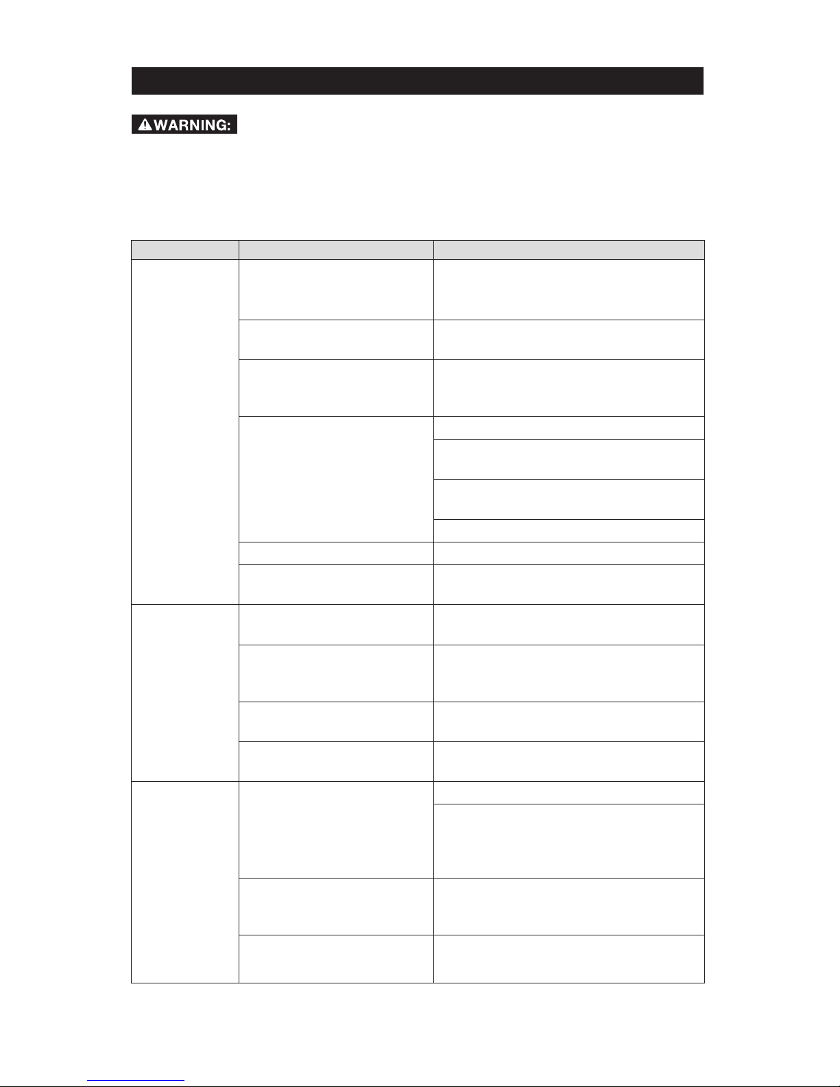
TROUBLESHOOTING
Risk of Unsafe Operation. Unit cycles automatically when
power is on. When servicing, you may be exposed to voltage sources, compressed air, or moving parts. Before servicing unit unplug or disconnect electrical supply to the air compressor, bleed tank of pressure, and allow the air
compressor to cool.
Problem Possible Cause Solution
The compressor
does not run.
□ There is a loss of power or
the motor is overheated.
□ Check for proper use of extension cord.
□ There is no power to the
unit.
□ Check to be sure the unit is plugged in.
□ The circuit breaker has
tripped or a fuse has blown
at the main power source.
□ Check the fuse/breaker.
□ The thermal overload
protector is actuated.
□ Turn the air compressor OFF (O).
□ Unplug the air compressor and wait until
the compressor cools down.
□ Plug the air compressor into an approved
outlet.
□ Turn the air compressor AUTO (I).
□ The pressure switch is bad. □ Bring the compressor to a service center.
□ The compressor has reached
automatic shutoff pressure.
□ Release the air from the tank until the
compressor restarts automatically.
The motor hums
while running
slowly, or it does
not run at all.
□ There is low voltage from
the power source.
□ Call an electrician.
□ The wrong gauge wire or
length of extension cord is
being used.
□ Check for proper gauge wire and cord
length.
□ There is a shorted or open
motor wiring.
□ Bring the compressor to a service center.
□ There is a defective check
valve or unloader.
□ Bring the compressor to a service center.
The fuses blow
or circuit breaker
trips repeatedly.
□ The incorrect fuse type is
being used.
□ Check for the proper fuse.
□ Use a time-delay fuse. Disconnect other
electrical appliances from the circuit
or operate the compressor on its own
branch circuit.
□ The wrong gauge wire or
length of extension cord
is used.
□ Check for the proper gauge wire and
cord length.
□ There is a defective check
valve or unloader.
□ Bring the compressor to a service center.

18- ENG
Problem Possible Cause Solution
The thermal
overload
protector cuts out
repeatedly.
□ There is low voltage from
the power source.
□ Call an electrician.
□ There is a lack of proper
ventilation, or the room
temperature is too high.
□ Move the compressor to a well-ventilated
area.
□ The wrong gauge wire or
length of extension cord is
being used.
□ Check for proper gauge wire and cord
length.
The air receiver
pressure drops
when the
compressor
shuts off.
□ The connections (fittings,
tubing, etc.) are loose and
leaking.
□ Check all connections with a soap and
water solution and tighten.
□ The drain valve is loose
or open.
□ Tighten the drain valve.
□ The check valve is leaking. □ Bring the compressor to a service center.
There is
excessive
moisture in the
discharge air.
□ There is excessive water in
the air tank.
□ Drain the tank.
□ The compressor is working
under a high humidity
environment.
□ Move the compressor to an area of less
humidity; use an air line filter.
The compressor
continuously
runs.
□ The pressure switch is
defective.
□ Bring the compressor to a service center.
□ An excessive amount of air
is being used.
□ Decrease the air usage; the compressor
is not large enough for the tool’s
requirement.
The air output
is lower than
normal.
□ The inlet valves are broken. □ Bring the compressor to a service center.
□ The connections (fittings,
tubing, etc.) are loose and
leaking.
□ Tighten the connections.
TROUBLESHOOTING

22- ENG
KIT NO. PART NO. KIT NAME REF NO.
1
E109152
Kit, Gasket 4 - 12
2
E105879
Kit, Oil Fill Cap 13 - 14
3
E109153
Kit, Oil Sight Gauge 10 - 11
4
E108923SV
Kit, L2 Motor/Pump Assembly w/RH Exhaust 1 - 26, 29
5 E100794 Kit, Air Filter 29 - 31
6 E109422 Kit, 3/8" Copper Outlet Tube 31 - 33
7 E109423 Kit, 1/4" Copper Pressure Relief Tube 35 - 37
8 E109875 Kit, Wheel (replaces one wheel only) 42 - 45
Replacement parts and service are available from your nearest authorized Service
Center. If the need arises, contact Product Service as listed.
When consulting with a Service Center or Product Service, refer to the model
number and serial number located on the serial label of the compressor. Proof of
purchase is required for all transactions and a copy of your sales receipt may be
requested.
Record the model number, serial number, and date purchased in the spaces
provided below. Retain your sales receipt and this manual for future reference.
When needing service, please contact the nearest authorized Service Center or
call:
PRODUCT SERVICE
In U.S.A. or Canada
Toll-Free: 1-888-895-4549
Fax: 1-507-723-5013
PARTS LIST
Model No. Serial No. Date Purchased
PARTS AND SERVICE
NOTE: Any part/kit number field without a number is not available. Descriptions are provided for
reference only. The Kit Number column represents that the part being offered is available in a kit.
One of each part per kit will be offered.

23 - ENG
LIMITED WARRANTY
PORTER-CABLE Industrial Tools are warranted from date of purchase.
2 Year – Limited warranty on oil-lubricated air compressor pumps.
1 Year – Limited warranty on all other air compressor components.
This warranty is not transferable to subsequent owners.
PORTER-CABLE will repair or replace, without charge, at PORTER-CABLE’S
option, any defects due to faulty materials or workmanship. For further detail of
warranty coverage and warranty repair information, call 1-(888)-895-4549
or visit portercable.com. This warranty does not apply to accessories or
damage caused where repairs have been made or attempted by others.
This warranty also does not apply to merchandise sold by PORTER-CABLE
which has been manufactured by and identified as the product of another
company, such as gasoline engines. Such manufacturer’s warranty, if any,
will apply. ANY INCIDENTAL, INDIRECT OR CONSEQUENTIAL LOSS,
DAMAGE OR EXPENSE THAT MAY RESULT FROM ANY DEFECT, FAILURE
OR MALFUNCTION OF THE PRODUCT IS NOT COVERED BY THIS
WARRANTY. Some states do not allow the exclusion of limitation of incidental
or consequential damages, so the above limitation or exclusion may not apply
to you. IMPLIED WARRANTIES, INCLUDING THOSE OF MERCHANTABILITY
OR FITNESS FOR A PARTICULAR PURPOSE, ARE LIMITED TO ONE YEAR
FROM THE DATE OF ORIGINAL PURCHASE.
Some states do not allow limitations on how long an implied warranty lasts, so
the above limitations may not apply to you.
What the Company Will Do: (the company) will cover parts and labor to
remedy substantial defects due to materials and workmanship during the
first year of ownership, with the exceptions noted below. Parts used in repair
of whole goods or accessories are warranted for the balance of the original
warranty period.
What is not covered Under This Warranty? Failures by the original retail
purchaser to install, maintain, and operate said equipment in accordance with
standard industry practices. Modifications to the product, or tampering with
components, or failure to comply with the specific recommendations of the
Company set forth in the owner’s manual, will render this warranty null and void.
The Company shall not be liable for any repairs, replacements, or adjustments
to the equipment, or any costs for labor performed by the purchaser without the
Company’s prior written approval. The effects of corrosion, erosion, surrounding
environmental conditions, cosmetic defects, and routine maintenance items, are
specifically excluded from this warranty. Routine maintenance items such as:
oil, lubricants, and air filters, as well as changing oil, air filters, belt tensioning,
etc… fall under the owner’s responsibility. Additional exclusions include: freight
damage, failures resulting from neglect, accident, or abuse, induction motors
when operated from a generator, oil leaks, air leaks, oil consumption, leaky
fittings, hoses, petcocks, bleeder tubes, and transfer tubes.

24- ENG
• The following components are considered normal wear items and are
not covered after the first year of ownership: Belts, sheaves, flywheels,
check valves, pressure switches, air unloaders, throttle controls,
electric motors, brushes, regulators, o-rings, pressure gauges, tubing,
piping, fittings, fasteners, wheels, quick couplers, gaskets, seals, air
filter housings, piston rings, connecting rods, and piston seals.
• Labor, service calls, and travel charges, are not covered after the first
year of ownership on stationary compressors (compressors without
handles, or wheels). Repairs requiring overtime, weekend rates, or any
other charges beyond the standard shop labor rate are not covered.
• Time required for orientation training for the service center to gain
access to the product, or additional time due to inadequate egress.
• Damage caused by incorrect voltage, improperly wired, or failure to
have a certified licensed electrician install the compressor, will render
this warranty null and void.
• Damage caused from inadequate filter maintenance.
• Pump wear or valve damage caused by using oil not specified.
• Pump wear or damage caused by any oil contamination.
• Pump wear or valve damage caused by failure to follow proper
maintenance guidelines.
• Operation below proper oil level or operation without oil.
• Gas Engines, if product is equipped with a gas engine, see engine
manual for specific engine manufacturer’s warranty coverage.
Parts purchased separately: The warranty for parts purchased separately
such as: pumps, motors, etc., are as follows:
From Date of Purchase
• All single & two stage pumps 1 year
• Electric motors 90 days
• Universal motor/pump 30 days
• All other parts 30 days
• No return authorization will be issued for electrical components once
items are installed.
How do You Get Service? In order to be eligible for service under this warranty
you must be the original retail purchaser, and provide proof of purchase from
one of the Company’s dealers, distributors, or retail outlet stores. Portable
compressors or components must be delivered, or shipped, to the nearest
Authorized Service Center. All associated freight costs and travel charges must
be borne by the consumer. Please call our toll free number 1-888-895-4549 for
assistance.
LIMITED WARRANTY
25 - ENG
LIMITED WARRANTY
THIS WARRANTY GIVES YOU SPECIFIC LEGAL RIGHTS, AND YOU MAY
ALSO HAVE OTHER RIGHTS WHICH VARY FROM STATE TO STATE.
THE COMPANY MAKES NO OTHER WARRANTY OR REPRESENTATION
OF ANY KIND WHATSOEVER, EXPRESSED OR IMPLIED, EXCEPT THAT
OF TITLE. ALL IMPLIED WARRANTIES, INCLUDING ANY WARRANTY OF
MERCHANTABILITY AND FITNESS FOR PARTICULAR PURPOSE ARE HEREBY
DISCLAIMED. LIABILITY FOR CONSEQUENTIAL AND INCIDENTAL DAMAGES
UNDER ANY AND ALL WARRANTIES, OTHER CONTRACTS, NEGLEGENCE,
OR OTHER TORTS IS EXCLUDED TO THE EXTENT EXCLUSION IS
PERMITTED BY LAW.
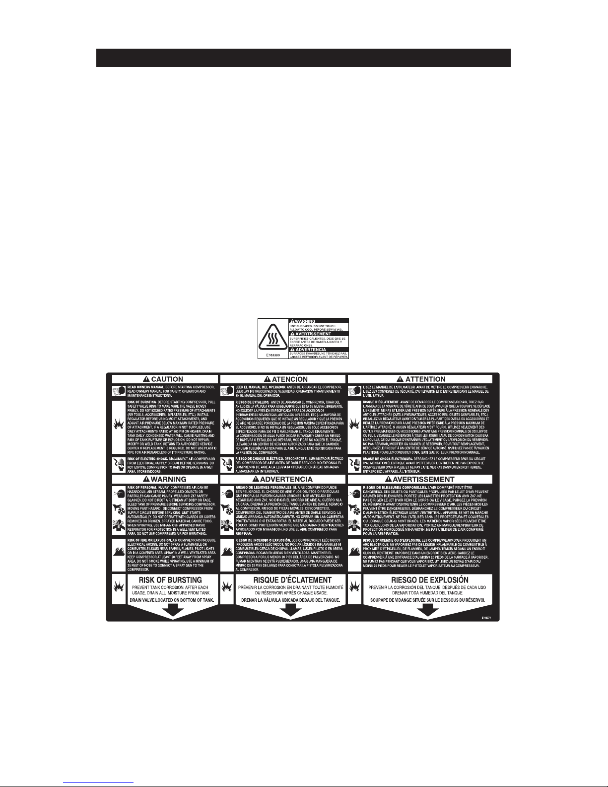
FREE WARNING LABEL REPLACEMENT: If your warning labels become illegible
or are missing, call
1-(888)-895-4549
for a free replacement.
 Loading...