

Page 1
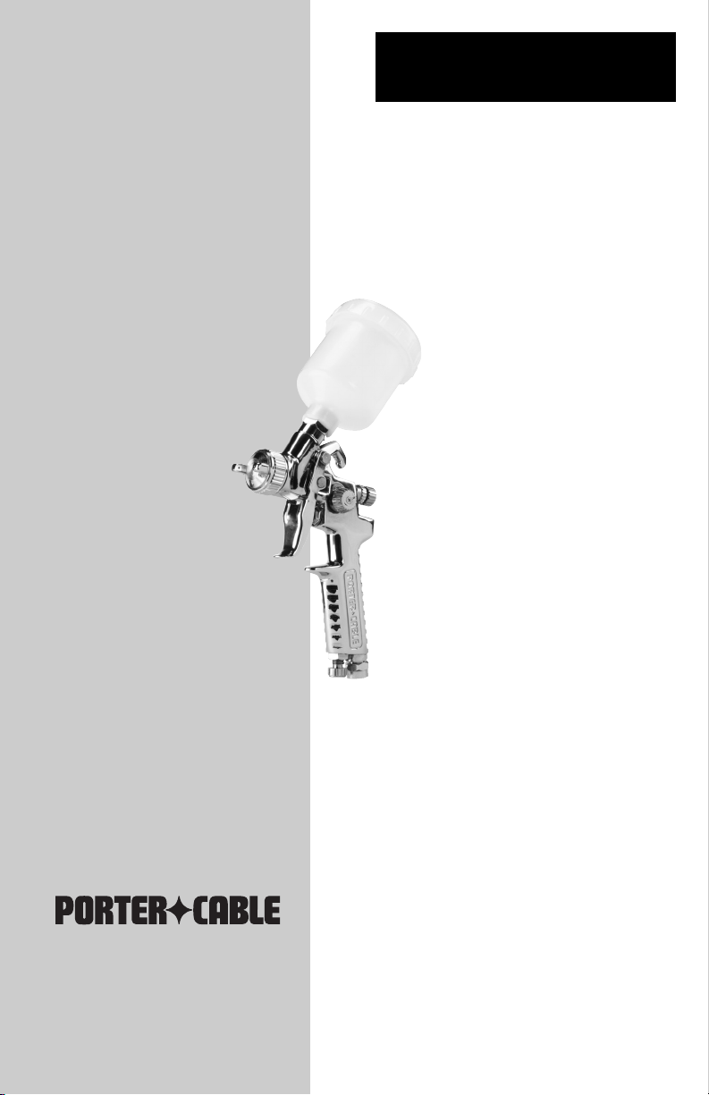
Gravity Feed Detail
Spray Gun
Part No. D25799-054-1
IMPORTANT
Please make certain that the person who is
to use this equipment carefully reads and
understands these instructions before
starting operations.
IMPORTANT
Veuillez vous assurer que la personne qui
utilise cet outil lit attentivement et comprend
ces instructions avant de commencer à utiliser
l'outil.
IMPORTANTE
Asegúrese de que la persona que va a usar esta
herramienta lea cuidadosamente y comprenda
estas instrucciones antes de empezar a
operarla.
ESPAÑOL: PÁGINA 9
FRANÇAIS: PAGE 17
Copyright © 2005 Porter-Cable Corporation
®
Instruction manual
Manual de
Instrucciones
Manuel d'instructions
MODEL PSH2
MODÈLE
PSH2
MODELO PSH2
To learn more about Porter-Cable visit
our website at:
http://www.porter-cable.com
Pour de plus amples renseignements
concernant Porter-Cable, consultez
notre site Web à l'adresse suivante:
http://www.porter-cable.com
Para obtener más información sobre
Porter-Cable, visite nuestro sitio web en:
http://www.porter-cable.com
Pistola para Pintar Detalles
por Rociado, Alimentada por
Gravedad
Pistolet à peinture détaillée à
alimentation par gravité
Page 2
2- ENG
D25799
• SAVE THESE INSTRUCTIONS •
The Following Hazards Can Occur During The Normal Use Of This Product:
The solvents 1,1,1-Trichloroethane and Methylene
Chloride can chemically react with the aluminum
used in most spray equipment, and this gun and
cup, to produce an explosion hazard and could
result in serious injury or death.
Read the label or data sheet for the material you
intend to spray.
1. Never use any type of spray coating material
containing these solvents.
2. Never use these solvents for equipment cleaning
or flushing.
3. If in doubt as to whether a material is compatible,
contact your material supplier.
SAFETY GUIDELINES - DEFINITIONS
indicates an imminently hazardous situation
which, if not avoided, will result in death or
serious injury.
indicates a potentially hazardous situation which,
if not avoided, could result in death or serious
injury.
indicates a potentially hazardous situation which,
if not avoided,may result in minor or moderate
injury
used without the safety alert symbol indicates
potentially hazardous situation which, if not
avoided, may result in property damage.
This manual contains
information that is
important for you to know and
understand. This information relates to protecting YOUR SAFETY and PREVENTING
EQUIPMENT PROBLEMS. To
help you recognize this information, we use the symbols below.
Please read the manual and
pay attention to these sections.
IMPROPER OPERATION OR MAINTENANCE OF THIS PRODUCT COULD
RESULT IN SERIOUS INJURY AND PROPERTY DAMAGE. READ AND UNDERSTAND ALL WARNINGS AND OPERATING INSTRUCTIONS BEFORE USING THIS
EQUIPMENT.
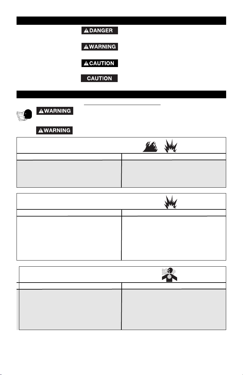
HAZARD
WHAT COULD HAPPEN HOW TO PREVENT IT
Risk of explosion or fire - flammable materials
IMPORTANT SAFETY INSTRUCTIONS
When paints or materials are sprayed, they are
broken into very small particles and mixed with air.
This will cause certain paints and materials to become extremely flammable and could result in
serious injury or death.
Never spray near open flames or pilot lights in
stoves or heaters.
Never smoke while spraying.
Provide ample ventilation when spraying indoors.
HAZARD
WHAT COULD HAPPEN HOW TO PREVENT IT
Risk of explosion - incompatible materials
HAZARD
WHAT COULD HAPPEN HOW TO PREVENT IT
Risk of breathing
Some paints, coatings and solvents may cause lung
damage, and burns if inhaled or allowed to come
into contact with skin or eyes.
Use a NIOSH approved mask or respirator and protective clothing designed for use with your specific
application and spray materials. Some masks
provide only limited protection against toxic materials and harmful paint solvent. Consult with a Safety
Expert or Industrial Hygienist if uncertain about your
equipment or materials.
Page 3
3- ENG
D25799
SPECIFICATIONS
Air Inlet 1/4 NPS
Maximum Air Pressure 60 psi.
Recommended Operating Air Pressure 35 psi.
Cup 133 cc (4.5 oz)
Air Consumption @ 60 PSI 3.6 SCFM
Prolonged exposure to air spray can result in permanent damage to hearing.
Always wear hearing protection when operating
spray equipment.
Spray guns operate at pressures and velocities
high enough to penetrate human and animal flesh,
which could result in amputation or other serious
injury.
! See a physician immediately!
Never place hands in front of nozzle.
Direct spray away from self and others.
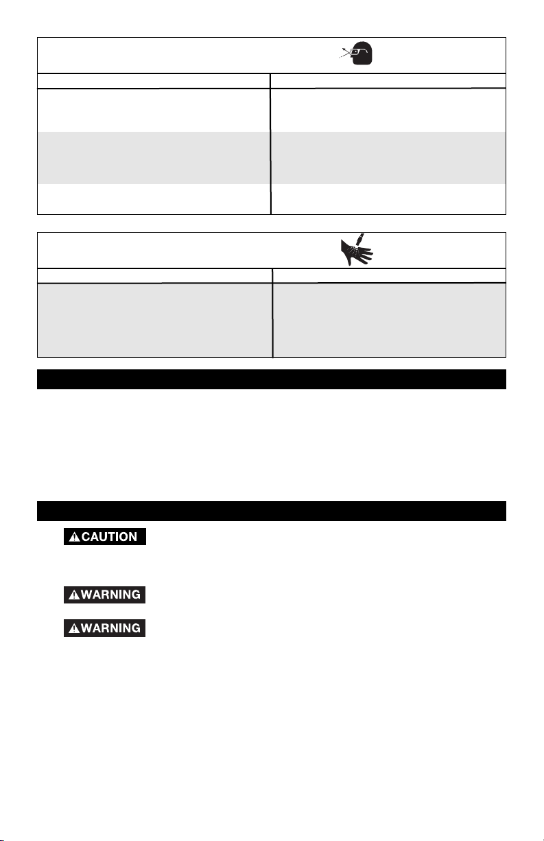
HAZARD
WHAT COULD HAPPEN HOW TO PREVENT IT
Risk of flying objects
HAZARD
WHAT COULD HAPPEN HOW TO PREVENT IT
Risk of injection
Certain parts are under pressure whenever the gun
is connected to a pressurized air line. These parts
may be propelled if the gun is disassembled.
Disconnect the gun from the air line, or completely
depressurize the air line whenever the gun is to be
disassembled.
Compressed air may propel dirt, metal shavings,
etc. and possibly cause an injury.
Never point any nozzle or sprayer toward a person
or part of the body.
Always wear ANSI 278.1 safety approved goggles
or glasses when spraying.
Before disassembly or removal of any part of gun or attached
components, shut off compressor, release pressure by depressing
trigger, and disconnect power source.
NEVER assume system pressure is zero!
TO AVOID CREATING AN EXPLOSIVE ATMOSPHERE, WORK ONLY
IN WELL VENTILATED AREAS.
USE OF A FACE MASK IS RECOMMENDED TO PREVENT INHALA-
TION OF TOXIC MATERIAL.
GENERAL INFORMATION
Page 4

4- ENG
D25799
Prior to shipment, this gun was treated with an anticorrosive agent. Before using this gun make
sure that it is carefully flushed with thinner.
1. The position of the air cap (H) horns will determine the
spray pattern. Loosen (G) air cap and rotate horns to
achieve desired pattern. Tighten air cap.
2. Attach material cup to the gun. NOTE: The (F) material
filter supplied is optional to protect against contaminants
and small particles. See parts list for material filter
orientation.
3. Attach air supply line to 1/4 NPS air inlet.
NEVER point spray gun at self or any
other person. Accidental discharge of
material may result in serious injury.
4. Adjust air pressure at air compressor.
DO NOT exceed 60 psi.
5. Depress spray gun trigger fully to spray material. NOTE: Depressing trigger partially will
cause only air to be released.
Adjust spray gun:
a. Amount of material released (density of “fan spray”) is controlled by (D) fluid control
knob. Turn knob counterclockwise to increase, or clockwise to decrease, the fluid flow.
b. Width of “fan spray” is governed by (B) pattern adjustment knob. Turn knob counter-
clockwise to increase, or clockwise to decrease, air flow.
c. Air quantity is controlled by (C) air-volume control knob. Turn knob counterclockwise to
increase, or clockwise to decrease, the air flow.
NOTE: Care should be exercised when handling spray gun to avoid damage to the orifice of the
air cap and tip of fluid nozzle. Damage to these parts results in irregular spray patterns.
DO NOT ATTEMPT
TO UNCLOG (BACK
FLUSH) SPRAY GUN BY SQUEEZING
TRIGGER WHILE HOLDING FINGER IN
FRONT OF FLUID NOZZLE.
Pressure may vary
according to
viscosity of material used. Maximum
working pressure of gun is 60 psi. DO
NOT EXCEED PRESSURE LIMIT OF
GUN OR ANY OTHER COMPONENT IN
SYSTEM!
Prior to daily
operation, make
certain that all connections and fittings
are secure. Check hose and all connections for a weak or worn condition
that could render system unsafe. All
replacement components such as
hose or fittings must have a working
pressure equal to or greater than
system pressure.
Horizontal position
Vertical position
OPERATION
(A) Air
Valve Nut
(E) Paint Cup
(G) Air Cap
(C) Air
Volume
Control Knob
(D) Fluid
Control
Knob
(B) Spray
Pattern
Adjustment
(H) Horns
(F) Material
Filter
Page 5

5- ENG
D25799
Always exercise extreme care when using any solvent or thinner.
Never clean gun near fire, flame, or any source of heat or sparks.
Properly dispose of used cleaning materials.
DO NOT soak entire spray gun in solvent or thinner for a long
period of time as this will destroy lubricants and possibly make
motion uneven. NEVER use lye or caustic alkaline solution for cleaning. Such solutions will attack aluminum alloy parts of gun.
It is important that spray gun be cleaned after daily use. Cleaning is accomplished by spraying
appropriate solvent or thinner through system. Wipe exterior of spray gun with solvent soaked
cloth or use cleaning brush(s) provided to remove any accumulated material.
Cleaning
(a) Empty material from gravity feed cup and replace with a suitable solvent.
(b) Operate trigger until all material traces have disappeared and gun is thoroughly clean.
(c) Clean air cap with brush.
IMPORTANT: Make certain air cap and fluid nozzle are kept clean at all times. If necessary, remove these two components and soak them in solvent. DO NOT use hard objects
to clean clogged holes. The smallest amount of damage may cause irregular spray
pattern.
NOTE: If fluid nozzle is to be removed for thorough cleaning, squeeze trigger to prevent dam-
age of fluid needle tip when unscrewing nozzle.
Lubrication
Lubrication procedures must be observed after thoroughly cleaning the gun to ensure effective,
high quality performance of spray gun.
1. Lubricate working points with straight mineral oil, or castor oil.
2. Periodically, place a few drops of oil on tapered sections of fluid nozzle to ensure easy operation of air cap. When spraying water base materials, coat fluid nozzle inside and
outside with straight mineral oil after each use.
3. Outer diameter of needle sleeve of fluid needle assembly must be lubricated occasionally
with straight mineral oil.
Change or Replace nozzle set
When changing nozzle set, make sure the complete nozzle set is exchanged. A set includes an
air cap, fluid nozzle, and fluid needle. NOTE: Assemble fluid nozzle before putting in fluid
needle.
MAINTENANCE
* Standard size is supplied with gun. Other nozzle sets should be ordered
separately. A set includes an air cap, fluid nozzle, and fluid needle.
Part Number
Nozzle Sets
Orifice Diameter
*D26400 0.8 mm (.031”)
D26401
D26402
1.0 mm (.039”)
1.2 mm (.047”)
Material
Waterborne
Waterborn
Multipurpose
Exchange of the self-tensioning needle packing
The fluid needle seal is effected by a Teflon packing with self-tensioning compression spring.
To change the packing during general overhaul, please use the socket spanner provided.
Page 6

6- ENG
D25799
Dried material is clogging side-port “A” and
causing side-port “B”
to blow spray towards
the clogged side
A.
Soak side-ports in thinner to
clean clog. DO NOT poke any
opening with hard objects.
B.
Dried material at fluid
nozzle “C” restricts air
flow
Loose air nozzle
Air pressure set too
high
Remove air nozzle. Wipe off fluid
tip using a cloth soaked in thinner
or by soft brush
Fasten nozzle securely
Reduce air pressure
C. Spitting, irregular
or fluttering spray
Fluid nozzle cracked or worn
Leak at thread of fluid nozzle
Leak at fluid needle
Needle packing worn out
Insufficient fluid in cup
Vent hole in container cover
clogged
Tighten or replace
Tighten fluid nozzle
Tighten compression nut
assembly or replace needle
packing
Replace packing
Fill cup with fluid
Clean Out
D. Split spray pattern
Air pressure too high
Turn pattern control knob
clockwise to decrease fan width.
Turn fluid needle adjusting nut
counterclockwise to increase fluid
flow
Material too heavy
Insufficient air pressure
Fluid pressure too high
Dried material on tip of fluid noz-
zle or air jets of air cap
Thin material or use larger orifice
fluid nozzle set
Increase pressure to within limit
Reduce pressure
Clean
Air needle partially closed
Dried material in air jets or air cap
Obstruction in air line
Remove obstruction
Reduce air pressure and/or open
fluid control knob
Air pressure to high for viscosity
of fluid
Loose cup or foreign substances
on/between cup thread and fluid
inlet
Tighten and clean or replace it
F. Inadequate air de-
livery
E. Unatomized or
spattered spray
G. Excessive fog
I. Material leaking
from nozzle when
trigger is released
H. Material leaking
from fluid inlet of
cup.
Worn fluid needle
Dried material in tip of nozzle
Loose packing nut
Replace
Clean
Tighten needle packing nut by
turning counterclockwise
Defective Pattern
Likely Cause Suggested Remedy
TROUBLESHOOTING
Open control knob
Clean
NOTICE: See parts list to identify parts referred to in these Troubleshooting steps.
Page 7

7- ENG
D25799
PARTS LIST
REF
NO DESCRIPTION PART NO
1 Air Nozzle with Cap D25194
2 Air Nozzle ------3 Washer ------4 Stainless Ring ------5 Brass Cap ------6 Fluid Nozzle D25199
7 Gasket D25200
8 Packing Screw for Paint Needle A11582
9 Teflon Seal D25202
10 Spring A11583
11 O-Ring D25204
12 Connector D25205
13 Plastic Cup D25206
14 Cover D25207
15 Trigger D25208
16 Trigger Pin D25209
17 Trigger Pin D25210
18 E-Ring D25211
19 Fluid Control Knob D25213
20 Lock Nut for Fluid Control Knob D25214
21 Spring for Paint Needle D25215
22 Paint Needle D25216
23 Washer D25217
24 Air Valve Assembly D25218
25 Screw ------26 Teflon Ring ------27 Air Valve ------28 Needle Valve ------29 Spring ------30 Screw D25224
31 Control Knob D25225
32 Spray Regulator Screw D25226
33 Air Connection D25227
34 Air Connection Valve Assembly D25228
40 Material Filter D25186
41 Socket Spanner D25189
42 Brush D25191
REF
NO DESCRIPTION PART NO
14
42
41
1
2345
15 16
18
67 91011
8
25 26 27 28 29
24
32
18
17
31
30
13
40
12
22 21 20 19
23
33
34
35
36
37
38
39
Page 8

LIMITED WARRANTY
PORTER-CABLE CORPORATION warrants to the original purchaser that all products covered under this warranty
are free from defects in material and workmanship. Products covered under this warranty include air compressors,
air tools, service parts, pressure washers, and generators, which have the following warranty periods:
3 YEARS - Limited warranty on 2-stage oil-free air compressor pumps that operate at 1725 RPM.
2 YEARS - Limited warranty on oil-lubricated air compressor pumps.
1 YEAR - Limited warranty on all other air compressor components.
2 YEARS - Limited warranty on electric generator alternators.
1 YEAR - Limited warranty on other generator components.
2 YEARS - Limited warranty on pneumatic air tools as described in Porter-Cable general catalog.
1 YEAR - Limited warranty on pressure washers used in consumer applications (i.e. personal residential
household usage only).
90 DAY - Pressure washers used for commercial applications (income producing) and service parts.
1 YEAR - Limited warranty on all accessories.
Porter-Cable will repair or replace, at Porter-Cable's option, products or components which have failed within the
warranty period.
Service will be scheduled according to the normal work flow and business hours at the
service center location, and the availability of replacement parts.
All decisions of Porter-Cable Corporation
with regard to this limited warranty shall be final.
This warranty gives you specific legal rights, and you may also have other rights which vary from state to state.
RESPONSIBILITY OF ORIGINAL PURCHASER (initial User):
• To process a warranty claim on this product, DO NOT return it to the retailer. The product must be evaluated by
an Porter-Cable Authorized Warranty Service Center. For the location of the nearest Porter-Cable Authorized
Warranty Service Center call 1-888-559-8550, 24 hours a day, 7 days a week.
• Retain original cash register sales receipt as proof of purchase for warranty work.
• Use reasonable care in the operation and maintenance of the product as described in the Owners Manual(s).
• Deliver or ship the product to the nearest Porter-Cable Authorized Warranty Service Center. Freight costs, if any,
must be paid by the purchaser.
• Air compressors with 60 and 80 gallon tanks will be inspected at the site of installation. Contact the nearest
Porter-Cable Authorized Warranty Service Center that provides on-site service calls, for service call
arrangements.
• If the purchaser does not receive satisfactory results from the Porter-Cable Authorized Warranty Service Center,
the purchaser should contact Porter-Cable.
THIS WARRANTY DOES NOT COVER:
• Merchandise sold as reconditioned, used as rental equipment, and floor or display models.
• Merchandise that has become damaged or inoperative because of ordinary wear, misuse*, cold, heat, rain,
excessive humidity, freeze damage, use of improper chemicals, negligence, accident, failure to operate the
product in accordance with the instructions provided in the Owners Manual(s) supplied with the product,
improper maintenance, the use of accessories or attachments not recommended by Porter-Cable, or
unauthorized repair or alterations.
* An air compressor that pumps air more than 50% during a one hour period is considered misuse because the
air compressor is undersized for the required air demand.
• Repair and transportation costs of merchandise determined not to be defective.
• Costs associated with assembly, required oil, adjustments or other installation and start-up costs.
• Expendable parts or accessories supplied with the product which are expected to become inoperative or
unuseable after a reasonable period of use, including but not limited to sanding disks or pads, saw and shear
blades, grinding stones, springs, chisels, nozzles, o-rings, air jets, washers and similar accessories.
• Merchandise sold by Porter-Cable which has been manufactured by and identified as the product of another
company, such as gasoline engines. The product manufacturer's warranty, if any, will apply.
• ANY INCIDENTAL, INDIRECT OR CONSEQUENTIAL LOSS, DAMAGE, OR EXPENSE THAT MAY RESULT
FROM ANY DEFECT, FAILURE OR MALFUNCTION OF THE PRODUCT IS NOT COVERED BY THIS
WARRANTY. Some states do not allow the exclusion or limitation of incidental or consequential damages, so
the above limitation or exclusion may not apply to you.
• IMPLIED WARRANTIES, INCLUDING THOSE OF MERCHANTABILITY OR FITNESS FOR A PARTICULAR
PURPOSE, ARE LIMITED TO ONE YEAR FROM THE DATE OF ORIGINAL PURCHASE. Some states do not
allow limitations on how long an implied warranty lasts, so the above limitations may not apply to you.
Porter-Cable Corporation
Jackson, TN USA
1-888-559-8550
®
 Loading...