

Porter-Cable PCC581B, PCC582B Instruction Manual
18V INFRARED THERMOMETER
Instruction manual
Manuel d'instructions
Manual de'instrucciones
www.portercable.com
INSTRUCTIVO DE OPERACIÓN,
CENTROS DE SERVICIO Y PÓLIZA DE
GARANTÍA.
ADVERTENCIA: LÉASE ESTE
INSTRUCTIVO ANTES DE USAR EL
PRODUCTO.
THERMOMÈTRE INFRAROUGE 18V
TERMÓMETRO INFRARROJO DE 18V
Battery and charger sold separately
CATALOG NUMBER
PCC581B

2
SAFETY GUIDELINES - DEFINITIONS
It is important for you to read and understand this manual. The information it contains
relates to protecting YOUR SAFETY and PREVENTING PROBLEMS. The symbols
below are used to help you recognize this information.
DANGER: Indicates an imminently hazardous situation which, if not avoided, will
result in death or serious injury.
WARNING: Indicates a potentially hazardous situation which, if not avoided,
could result in death or serious injury.
CAUTION: Indicates a potentially hazardous situation which, if not avoided, may
result in minor or moderate injury.
NOTICE: Used without the safety alert symbol indicates a potentially hazardous
situation which, if not avoided, may result in property damage.
General Power Tool Safety Warnings
WARNING: Read all safety warnings and all instructions. Failure to
follow the warnings and instructions may result in electric shock, fire and/or
serious injury.
Save all warnings and instructions for future reference.
The term “power tool” in the warnings refers to your mains-operated (corded)
power tool or battery-operated (cordless) power tool.
1) Work area safety
a) Keep work area clean and well lit. Cluttered or dark areas invite accidents.
b) Keep children and bystanders away while operating a power tool.
Distractions can cause you to lose control.
2) Personal safety
a) Stay alert, watch what you are doing and use common sense when
operating a power tool. Do not use a power tool while you are tired or under
the influence of drugs, alcohol or medication. A moment of inattention while
operating power tools may result in serious personal injury.
b) Use personal protective equipment. Always wear eye protection. Protective
equipment such as dust mask, non-skid safety shoes, hard hat, or hearing
protection used for appropriate conditions will reduce personal injuries.
c) Prevent unintentional starting. Ensure the switch is in the off-position
before connecting to power source and/or battery pack, picking up or
carrying the tool. Carrying power tools with your finger on the switch or
energizing power tools that have the switch on invites accidents.
d) Do not overreach. Keep proper footing and balance at all times. This enables
better control of the power tool in unexpected situations.
e) Dress properly. Do not wear loose clothing or jewellery. Keep your hair,
clothing and gloves away from moving parts. Loose clothes, jewellery or long
hair can be caught in moving parts.
3) Power tool use and care
a) Do not use the power tool if the switch does not turn it on and off. Any power
tool that cannot be controlled with the switch is dangerous and must be repaired.
b) Disconnect the plug from the power source and/or the battery pack from the
power tool before making any adjustments, changing accessories, or
storing power tools. Such preventive safety measures reduce the risk of starting
the power tool accidentally.
c) Store idle power tools out of the reach of children and do not allow persons
unfamiliar with the power tool or these instructions to operate the power
tool. Power tools are dangerous in the hands of untrained users.
d) Maintain power tools. Check for misalignment or binding of moving parts,
breakage of parts and any other condition that may affect the power toolʼs

3
o
peration. If damaged, have the power tool repaired before use. Many
accidents are caused by poorly maintained power tools.
e) Use the power tool, accessories and tool bits etc., in accordance with these
instructions, taking into account the working conditions and the work to be
performed. Use of the power tool for operations different from those intended
could result in a hazardous situation.
4) Battery tool use and care
a) Recharge only with the charger specified by the manufacturer. A charger that
is suitable for one type of battery pack may create a risk of fire when used with
another battery pack.
b) Use power tools only with specifically designated battery packs. Use of any
other battery packs may create a risk of injury and fire.
c) When battery pack is not in use, keep it away from other metal objects like
paper clips, coins, keys, nails, screws, or other small metal objects that can
make a connection from one terminal to another. Shorting the battery
terminals together may cause burns or a fire.
d) Under abusive conditions, liquid may be ejected from the battery; avoid
contact. If contact accidentally occurs, flush with water. If liquid contacts
eyes, additionally seek medical help. Liquid ejected from the battery may cause
irritation or burns.
5) Service
a) Have your power tool serviced by a qualified repair person using only identical
replacement parts. This will ensure that the safety of the power tool is maintained.
Safety Information for IR Thermometers
WARNING: Do not disassemble or modify the IR thermometers. There are no
user serviceable parts inside. Serious eye injury could result.
• Do not operate the IR thermometers in explosive atmospheres, such as in the
presence of flammable liquids, gases, or dust. Power tools create sparks which
may ignite the dust or fumes.
• Use the IR thermometer only with the specifically designated PORTER-CABLE
batteries. Use of any other batteries may create a risk of fire.
• Store the IR thermometer out of reach of children and other untrained
persons. Lasers are dangerous in the hands of untrained users.
• Tool service must be performed only by qualified repair personnel. Service or
maintenance performed by unqualified personnel may result in injury. To locate
your nearest PORTER-CABLE service center call (888) 848-5175 or go to our
website www.portercable.com.
• Do not use optical tools such as a telescope or transit to view the laser beam.
Serious eye injury could result.
• Do not place the IR thermometer in a position which may cause anyone to
intentionally or unintentionally stare into the laser beam. Serious eye injury
could result.
• Do not disassemble the IR thermometer. There are no user serviceable parts
inside.
• Do not modify the IR thermometer in any way. Modifying the tool may result in
hazardous laser radiation exposure.
• Do not operate the IR thermometer around children or allow children to
operate the IR thermometer. Serious eye injury may result.
• Do not remove or deface warning labels. Removing labels increases the risk of
exposure to radiation.
• Do not use IR thermometer for testing temperatures of cooked or uncooked
food.
• Do not use for taking human or animal body temperatures.
WARNING: Burn hazard. The reading may not be accurate if the thermometer
is in the presence of strong electromagnetic fields (such as arc welders, induction
heaters, ratio transmitters, etc.). Do not use the IR thermometer under these
conditions.

4
WARNING: ALWAYS use safety glasses. Everyday eyeglasses are NOT safety
glasses. Also use face or dust mask if cutting operation is dusty. ALWAYS WEAR
CERTIFIED SAFETY EQUIPMENT:
• ANSI Z87.1 eye protection (CAN/CSA Z94.3)
CAUTION: When not in use, place tool on its side on a stable surface where
it will not cause a tripping or falling hazard. Some tools with large battery packs will
stand upright on the battery pack but may be easily knocked over.
Liquid Crystal Display (First Aid Measures)
• If liquid crystal comes in contact with your skin:
Wash area off completely with plenty of water. Remove contaminated clothing.
• If liquid crystal gets into your eye:
Flush the affected eye with clean water and then seek medical attention.
• If liquid crystal is swallowed:
Flush your mouth thoroughly with water. Drink large quantities of water and induce
vomiting. Then seek medical attention.
Li-Ion Battery Packs and Chargers
Battery: Li-Ion 18V
Charger: Li-Ion
PC18BL
PC18BLX
PC18BLEX
PCLMVC
PCXMVC
Description Cat. #
NI-CD Battery Packs and Chargers
This product can accept any of the batteries and chargers listed in the chart below.
Battery: NI-CD 18V
Charger: NI-CD
PC18B
PCMVC
PCXMVC
Description Cat. #
5
F
UNCTIONAL
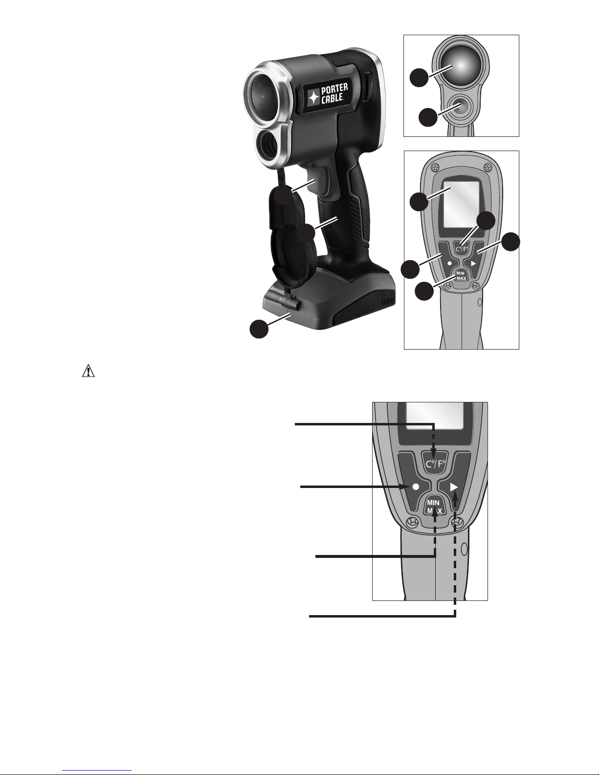
DESCRIPTION FIG. 1
A.) Measurement trigger
B.) Main handle
C.) 18V Battery compartment
D.) LED Color Indicator
E.) IR sensor
F.) LCD screen
G.) Record button
H.) Playback button
I.) Tolerance setting for
“HOT” and “COLD” spot
J.) C/F Mode Button: Used
to set temperature units
of measure (Celsius or
Fahrenheit).
C
A
B
D
E
G
F
J
I
H
Temperature setting button: This button
changes displayed temperature unit between
Fahrenheit or Centigrade.
Record button: This function records up to
10 readings. When recording the temperature
reading, the LCD screen will flash twice to
indicate the recording has been completed.
Temperature threshold button: This function
changes the temperature setting of when the
LED light turns green, red, blue or off.
Recorded Temperature Play Back button:
This button allows the user to review previously
recorded temperature data (up to 10
recordings). When in the play back mode, the
unit can switch back to temperature scanning
mode by pressing the Record button.
To erase the recorded data, press the Play
Back button to the desired temperature data.
Press and hold the Play Back button until the
LCD screen reads "- - - - ".
WARNING: Never modify the power tool or any part of it. Damage or personal
injury could result. SAVE THESE INSTRUCTIONS FOR FUTURE USE.
- FIG. 1
- FIG. 2

6
•
When using an extension cord, be sure to use one heavy enough to carry the current
your product will draw. An undersized cord will cause a drop in line voltage resulting
in loss of power and overheating. The following table shows the correct size to use
depending on cord length and nameplate ampere rating. If in doubt, use the next
heavier gage. The smaller the gage number, the heavier the cord.
Recommended Minimum Wire Size for Extension Cords
Total Length of Cord
25 ft. 50 ft. 75 ft. 100 ft. 125 ft. 150 ft. 175 ft.
7.6 m 15.2 m 22.9 m 30.5 m 38.1 m 45.7 m 53.3 m
Wire Size AWG
18 18 16 16 14 14 12
Important Safety Instructions for Battery Chargers
SAVE THESE INSTRUCTIONS: This manual contains important safety instructions for
battery chargers.
• Before using charger, read all instructions and cautionary markings on charger, battery
pack, and product using battery pack.
WARNING: Shock hazard. Do not allow any liquid to get inside charger.
CAUTION: Burn hazard. To reduce the risk of injury, charge only designated
PORTER-CABLE batteries. Other types of batteries may burst causing personal injury and
damage.
CAUTION: Under certain conditions, with the charger plugged in to the power
supply, the charger can be shorted by foreign material. Foreign materials of a conductive
nature such as, but not limited to, steel wool, aluminum foil, or any buildup of metallic
particles should be kept away from charger cavities. Always unplug the charger from the
power supply when there is no battery pack in the cavity. Unplug charger before
attempting to clean.
WARNING:
• DO NOT attempt to charge the battery pack with any chargers other than the ones
in this manual. The charger and battery pack are specifically designed to work together.
• These chargers are not intended for any uses other than charging designated
PORTER-CABLE rechargeable batteries. Any other uses may result in risk of fire,
electric shock or electrocution.
• Do not expose charger to rain or snow.
• Pull by plug rather than cord when disconnecting charger. This will reduce risk of
damage to electric plug and cord.
• Make sure that cord is located so that it will not be stepped on, tripped over, or
otherwise subjected to damage or stress.
• Do not use an extension cord unless it is absolutely necessary. Use of improper
extension cord could result in risk of fire, electric shock, or electrocution.
• An extension cord must have adequate wire size (AWG or American Wire Gauge)
for safety. The smaller the gauge number of the wire, the greater the capacity of the
cable, that is 16 gauge has more capacity than 18 gauge. When using more than one
extension to make up the total length, be sure each individual extension contains at
least the minimum wire size.
• Do not place any object on top of charger or place the charger on a soft surface
that might block the ventilation slots and result in excessive internal heat. Place
the charger in a position away from any heat source. The charger is ventilated
through slots in the top and the bottom of the housing.
• Do not mount charger on wall or permanently affix charger to any surface. The
charger is intended to use on a flat, stable surface (i.e., table top, bench top).
• Do not operate charger with damaged cord or plug — have them replaced immediately.
• Do not operate charger if it has received a sharp blow, been dropped, or
otherwise damaged in any way. Take it to an authorized service center.
• Do not disassemble charger; take it to an authorized service center when service or
repair is required. Incorrect reassembly may result in a risk of electric shock,
electrocution or fire.

7
•
Disconnect the charger from the outlet before attempting any cleaning. This will
reduce the risk of electric shock. Removing the battery pack will not reduce this risk.
• NEVER attempt to connect 2 chargers together.
• The charger is designed to operate on standard household electrical power (120
Volts). Do not attempt to use it on any other voltage.
SAVE THESE INSTRUCTIONS
Important Safety Instruction for Battery Packs
WARNING: For safe operation, read this manual and manuals originally supplied
with tool before using the charger.
The battery pack is not fully charged out of the carton. Before using the battery pack
and charger, read the safety instructions below. Then follow charging procedures outlined.
READ ALL INSTRUCTIONS
• Do not incinerate the battery pack even if it is severely damaged or is
completely worn out. The battery pack can explode in a fire. Toxic fumes and
materials are created when Li-Ion battery packs are burned.
• Do not charge or use battery in explosive atmospheres, such as in the presence of
flammable liquids, gases or dust. Inserting or removing the battery from the charger
may ignite the dust or fumes.
• If battery contents come into contact with the skin, immediately wash area with
mild soap and water. If battery liquid gets into the eye, rinse water over the open eye for
15 minutes or until irritation ceases. If medical attention is needed, the battery electrolyte
for Li-Ion batteries is composed of a mixture of liquid organic carbonates and lithium
salts. For NI-CD batteries it is a 25-35% solution of potassium hydroxide.
• Contents of opened battery cells may cause respiratory irritation. Provide fresh air.
If symptoms persist, seek medical attention.
WARNING: Burn hazard. Battery liquid may be flammable if exposedto spark orflame.
• Charge the battery packs only in PORTER-CABLE chargers.
• DONOTsplash orimmerseinwater orother liquids. This may cause premature cell failure.
• Do not store or use the tool and battery pack in locations where the temperature
may reach or exceed 105°F (40˚C) (such as outside sheds or metal buildings in
summer).
WARNING: Never attempt to open the battery pack for any reason. If battery pack
case is cracked or damaged, do not insert into charger. Do not crush, drop or damage
battery pack. Do not use a battery pack or charger that has received a sharp blow, been
dropped, run over or damaged in any way (i.e., pierced with a nail, hit with a hammer,
stepped on). Damaged battery packs should be returned to service center for recycling.
Battery Cap Information
Battery storage and carrying caps are provided for use whenever the
battery is out of the tool or charger. Remove cap before placing battery in
charger or tool.
WARNING: Fire hazard. Do not store or carry battery so that metal objects can
contact exposed battery terminals. For example, do not place battery in aprons,
pockets, tool boxes, product kit boxes, drawers, etc., with loose nails, screws, keys, etc.
Transporting batteries can possibly cause fires if the battery terminals inadvertently
come in contact with conductive materials such as keys, coins, hand tools and the
like. The US Department of Transportation Hazardous Material Regulations (HMR)
actually prohibit transporting batteries in commerce or on airplanes (i.e., packed in
suitcases and carry-on luggage) UNLESS they are properly protected from short circuits.
So when transporting individual batteries, make sure that the battery terminals are
protected and well insulated from materials that could contact them and cause a short
circuit. NOTE: Batteries should not be put in checked baggage.
Battery Cap

Storage Recommendations
1. The best storage place is one that is cool and dry away from direct sunlight and
excess heat or cold.
2. Long storage will not harm the battery pack or charger.
Charging Procedure
PORTER-CABLE chargers are designed to charge PORTER-CABLE battery packs in
30-60 minutes depending on the pack being charged.
1. Plug the charger into an appropriate outlet before inserting the battery pack.
2. Insert the battery pack into the charger.
3. The LED will flash indicating that the battery is being charged.
4. The completion of charge is indicated by the LED remaining on continuously.
The pack is fully charged and may be used at this time or left on the charger.
Charger Diagnostics
The charger is designed to detect certain problems that can arise with the battery
packs or the power source. Problems are indicated by one LED flashing in different
patterns.
Bad Battery
The charger can detect a weak or damaged battery. The LED flashes in the
pattern indicated on the label. If you see this bad battery blink pattern, do not
continue to charge the battery. Return it to a service center or a collection site
for recycling.
Hot/Cold Pack Delay
When the charger detects a battery that is excessively hot or excessively cold, it
automatically starts a Hot/Cold Pack Delay, suspending charging until the
battery has normalized. After this happens, the charger automatically switches to
the Pack Charging mode. This feature ensures maximum battery life. The light
flashes in the pattern indicated on the label.
Problem Power Line
When the charger is used with some portable power sources such as generators
or sources that convert DC to AC, the charger may temporarily suspend
operation. The LED flashes in the pattern indicated on the label. This indicates
that the power source is out of limits.
Leaving the Battery In the Charger
The charger and battery pack can be left connected with the LED glowing indefinitely.
The charger will keep the battery pack fresh and fully charged. This charger features
an automatic tune-up mode which equals or balances the individual cells in the battery
pack to allow it to function at peak capacity. Battery packs should be tuned up weekly
or whenever the battery no longer delivers the same amount of work. To use the
automatic tune-up mode, place the battery pack in the charger and leave it for at least 8 hours.
Important Charging Notes
1. Longest life and best performance can be obtained if the battery pack is charged
when the air temperature is between 65°F and 75°F (18°- 24°C). DO NOT charge the
battery pack in an air temperature below +40°F (+4.5°C), or above +105°F (+40.5°C).
This is important and will prevent serious damage to the battery pack.
2. The charger and battery pack may become warm to touch while charging. This is a
normal condition, and does not indicate a problem. To facilitate the cooling of the
battery pack after use, avoid placing the charger or battery pack in a warm
environment such as in a metal shed, or an uninsulated trailer.
3. If the battery pack does not charge properly:
a. Check current at receptacle by plugging in a lamp or other appliance
b. Check to see if receptacle is connected to a light switch which turns power off
when you turn out the lights.
c. Move charger and battery pack to a location where the surrounding air
temperature is approximately 65°F - 75°F (18°- 24°C).
d. If charging problems persist, take the tool, battery pack and charger to your
local service center.
8
9
4
. The battery pack should be recharged when it fails to produce sufficient power on
jobs which were easily done previously. DO NOT CONTINUE to use under these
conditions. Follow the charging procedure. You may also charge a partially used pack
whenever you desire with no adverse affect on the battery pack.
5. Foreign materials of a conductive nature such as, but not limited to, steel wool,
aluminum foil, or any buildup of metallic particles should be kept away from charger
cavities. Always unplug the charger from the power supply when there is no battery
pack in the cavity. Unplug charger before attempting to clean.
6. Do not freeze or immerse charger in water or any other liquid.
WARNING: Shock hazard. Do not allow any liquid to get inside charger. Never
attempt to open the battery pack for any reason. If the plastic housing of the battery pack
breaks or cracks, return to a service center for recycling.
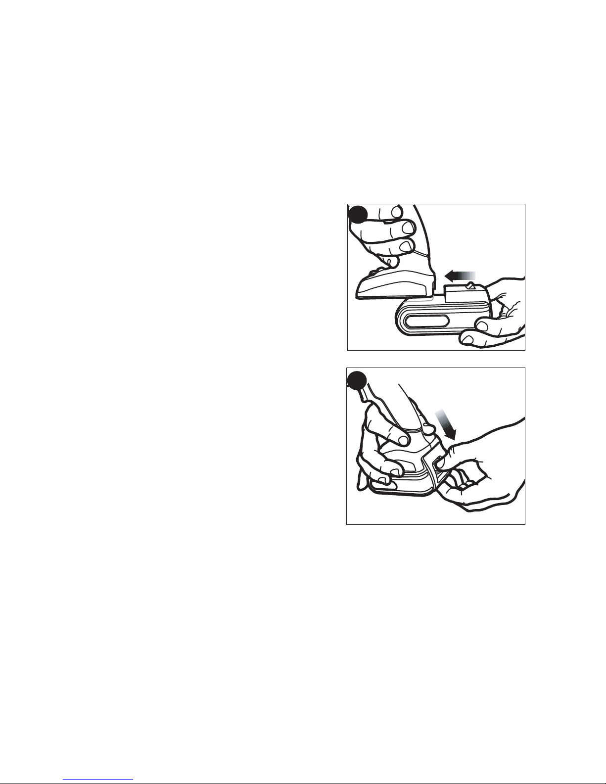
Installing and Removing the Battery Pack
TO INSTALL BATTERY PACK: Insert battery pack
into tool as shown in figure 3. Make sure battery
pack is fully seated and fully latched into position.
TO REMOVE BATTERY PACK: Depress the
battery release button as shown in figure 4 and pull
battery pack out of tool.
SAVE THESE INSTRUCTIONS FOR FUTURE USE.
Introduction
The PCC581 IR Thermometeruses an infrared sensor to find leaks along walls,
molding, ductwork and more. The auto color change feature provides quick, intuitive
feedback, showing you where to caulk, insulate, etc.
Once you have determined the location of these leaks, you can properly seal your
home including basic weather stripping and insulation.
Safety Instructions
• Do not operate the IR Thermometer in explosive atmospheres, such as in the presence
of flammable liquids, gases, or dust.
• Use only with the specifically designated batteries. Use of any other batteries may
create a risk of fire.
• The IR Thermometer measures surface temperature, not interior temperature. Do not
use for medical purposes.
• Do not use to determine if meat is cooked enough to eat.
3
4

10
Switching On and Off
• Press the ON/OFF button to turn the unit on.
• Press the ON/OFF button a second time to turn the unit off.
NOTE: The unit will automatically turn off after 10 minutes. External Operating
Temperature Range is -4
o
F to 140oF (-10oC to 60oC).
Setting Threshold for Color Change:
• For detecting small temperature changes of 1º F (0.5º C), press the +/- TEMP button to
set to the 1º setting on the LCD screen of the detector.
• For detecting medium temperature changes of 5º F (3º C), press the +/- TEMP button
to set to the 5º setting on the LCD screen of the detector.
• For detecting large temperature changes of more than 10º F (5.5º C), press the +/-
TEMP button to set to the 10º setting on the LCD screen of the detector.
• If you do not want the LED spot to change color, press the +/- TEMP button to set at "- - ".
You can change the threshold setting while you are scanning. If the color is changing
erratically, try increasing the "+/- TEMP" setting. If you see a temperature difference on
the screen, but the light is not changing color, try reducing the "+/- TEMP" setting.
Using the IR Thermometer
• Aim the unit near the location you want to scan for a draft or thermal leak. This initial
aim point will be your reference target.
• Squeeze the On/Off button.
• Keep the unit aimed at the reference target until the green light shines on the
target and a Reference Temperature appears on the screen.
• Slowly scan the IR Thermometer across the area of interest. If the scanned
temperature is hotter than the reference temperature by more than the threshold, the
light will turn from green to red. If the scanned temperature is colder than the reference
temperature by more than the threshold, the light will turn from green to blue.
Examples of Use:
• Scan around a light fixture to determine if ceiling insulation was removed during
installation.
• Scan along window and door sills to see where to add weather-stripping.
• Scan where a wall and the floor meet to find drafts that should be caulked.
• Scan an attic door to see if you need to add insulation.
NOTES*:
• Shiny or polished surfaces can give inaccurate readings. To compensate for this, cover
the surface with masking tape or flat colored paint. When the tape or paint reaches the
same temperature as the target underneath, measure the temperature of the item.
Emissivity describes the energy-emitting characteristics of materials. Materials with low
emissivity value such as shiny or polished surface can give inaccurate readings.
• The thermometer cannot measure through transparent surfaces such as glass or
plastic. It will measure the surface temperature instead.
• Steam, dust, smoke, and other optical obstructions can prevent accurate
measurement. Hold the thermometer back and at an angle for an accurate
measurement.
11
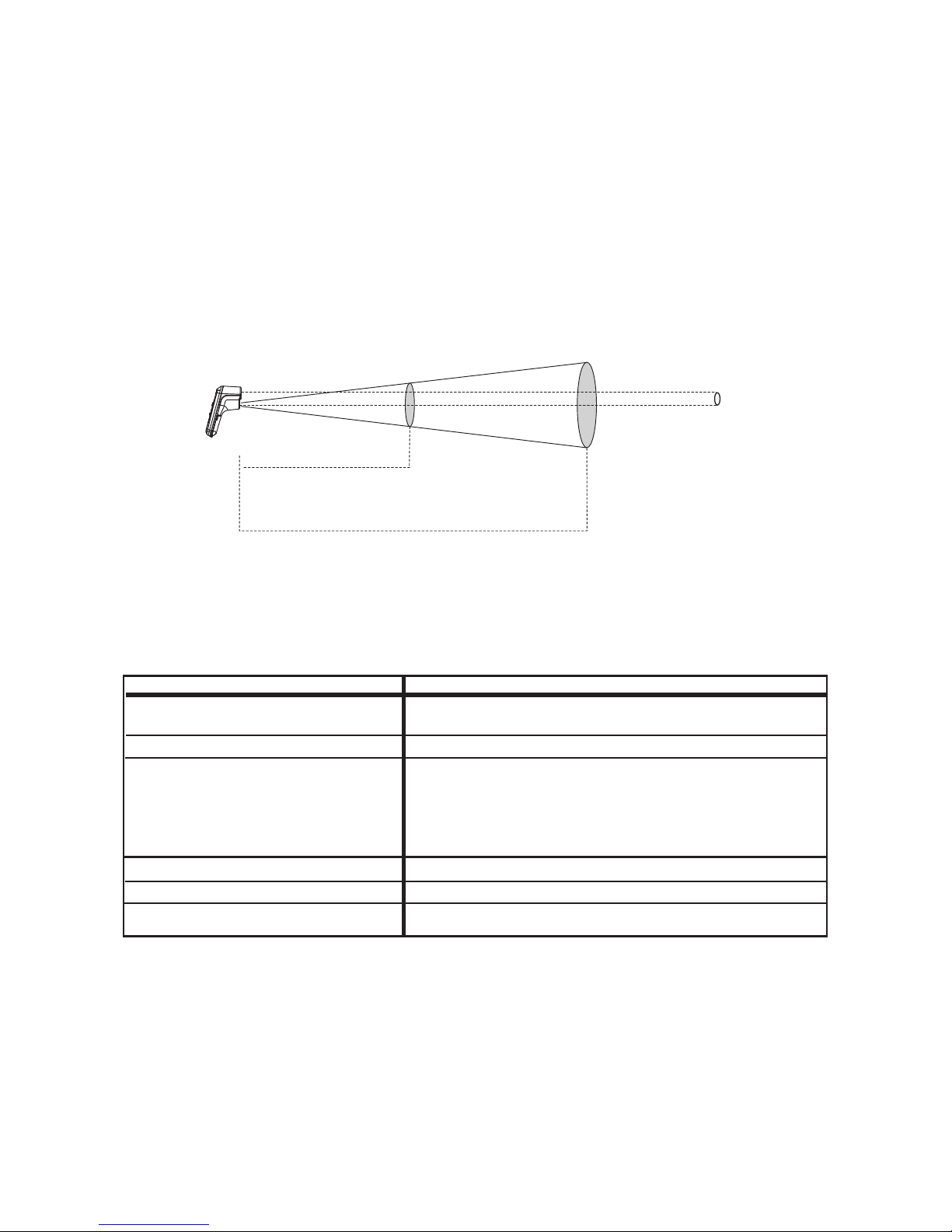
Field of View
The IR Thermometer measures temperature over an area that may be larger than
the LED spot, especially if you are far away from the surface you are measuring. The
diameter of the measured area is 1/12 the distance from the thermometer. In other
words, if you are 12 inches (304 mm) from the target, the thermometer will measure the
average temperature over a circle 1 inch (25mm) in diameter. As shown in the
illustration below, the farther the distance from the target, the larger the measured area.
If you are just looking for hot and cold areas, it's OK if the scanned area is larger than
your target. However, if you want to accurately measure the temperature of an object,
move the thermometer close so that the scanned area is about half the size of the
object you want to measure.
Output Specifications
24 inches
(610mm)
12 inches
(305mm)
1
i
n
c
h
2
i
n
c
h
e
s
(
2
5
m
m
)
(
5
1
m
m
)
Sensing Area Diameter
Distance to Target
LED Spot
Parameter Specification
Functional Temperature Range -22ºF to 590ºF (-30ºC to 310ºC)
Temperature Resolution 0.1°F (0.1°C)
Temperature Accuracy* 68º F to 590º F (20ºC to 310ºC): +/- 1ºF or 1%
-22º F to 68º F (-30ºC to 20ºC): +/- 1.5ºF
accuracies at a distance of 12 inches (304mm)
Response Time <1 second
Field of View 12:1 ratio, distance to sensing diameter
Threshold for LED color transition Adjustable between 4 fixed settings:
(1ºF, 5ºF, and 10ºF, and no color change)

12
The RBRC™ Seal
The RBRC™ (Rechargeable Battery Recycling Corporation) Seal on the
Lithium Ion or Ni-Cd battery (or battery pack) indicates that the costs to
recycle the battery (or battery pack) at the end of its useful life have already
been paid by PORTER-CABLE.
RBRC™ in cooperation with PORTER-CABLE and other battery users, has established
programs in the United States to facilitate the collection of spent Lithium Ion or Ni-Cd
batteries. Help protect our environment and conserve natural resources by returning the
spent Lithium Ion or Ni-Cd battery to an authorized PORTER-CABLE service center or to
your local retailer for recycling. You may also contact your local recycling center for
information on where to drop off the spent battery.
RBRC™ is a registered trademark of the Rechargeable Battery Recycling Corporation.
Maintenance
Use only mild soap and damp cloth to clean the tool. Never let any liquid get inside the
tool; never immerse any part of the tool into a liquid.
Replacement Parts
Use only identical replacement parts. For a parts list or to order parts,visit our service website at
www.portercable.com. You can also order parts from your nearest PORTER-CABLE Factory
Service Center or PORTER-CABLE AuthorizedWarranty Service Center. Or, you can call our
Customer Care Center at (888) 848-5175.
Service and Repairs
All quality toolswill eventually require servicing and/or replacement of parts. For information about
PORTER-CABLE, its factory service centers or authorized warranty servicecenters, visitour
website at www.portercable.comor call our Customer Care Center at (888) 848-5175. All repairs
made by our service centersare fully guaranteed against defective material and workmanship. We
cannot guarantee repairs made or attempted by others.
You can also write to us for information at PORTER-CABLE, 4825Highway 45 North,Jackson,
Tennessee 38305, (888) 848-5175 - Attention: Product Service. Be sure to include all of the
information shown on the nameplate of your tool (model number, type, serial number, etc.).
Accessories
WARNING: Since accessories, other than those offered by PORTER-CABLE, have
not been tested with this product, use of such accessories with this tool could be
hazardous. To reduce the risk of injury, only PORTER-CABLE recommended
accessories should be used with this product.
A complete line of accessories is available from your PORTER-CABLE Factory Service
Center or a PORTER-CABLE Authorized Warranty Service Center. Please visit our
Web Site www.portercable.com for a catalog or for the name of your nearest supplier.

13
TROUBLESHOOTING
Problem Possible Solution
• The display is hard to read, the LED light • Replace battery.
becomes dim, or the BAT symbol appears
on the LCD screen.
• The LED spot color changes erratically. • First, try increasing the
threshold level.
• If that doesn't work, turn the
thermometer off. Aim the
thermometer at a different
reference target and turn
the thermometer back on. Keep
the thermometer aimed at the
reference target until the green
spot appears and the LCD
screen shows a reference
temperature.
• The LED spot immediately turns red or • You may have moved the
blue before I have a chance to scan the area. thermometer before it had a
chance to lock in the reference
temperature. Turn the
thermometer off, aim it at the
reference target, then turn it
back on. Do not move the
thermometer until the green
spot appears and the LCD
screen shows a reference
temperature.
Forassistance withyourproduct,visit our website at www.portercable.com for a list of service
centers, or call the PORTER-CABLE Customer Care Center at (888) 848-5175.
THREE YEAR LIMITED WARRANTY
PORTER-CABLE will repair or replace, without charge, any defects due to faulty
materials or workmanship for three years from the date of purchase for tools (two
years for batteries). This warranty does not cover part failure due to normal wear or
tool abuse. For further detail of warranty coverage and warranty repair information,
visit www.portercable.com or call (888) 848-5175. This warranty does not apply to
accessories or damage caused where repairs have been made or attempted by
others. This warranty gives you specific legal rights and you may have other rights
which vary in certain states or provinces.
In addition to the warranty, PORTER-CABLE tools are covered by our:
1 YEAR FREE SERVICE: PORTER-CABLE will maintain the tool and replace worn
parts caused by normal use, for free, any time during the first year after purchase.
90 DAY MONEY BACK GUARANTEE: If you are not completely satisfied with the
performance of your PORTER-CABLE Power Tool for any reason, you can return it
within 90 days from the date of purchase with a receipt for a full refund – no questions asked.
LATIN AMERICA: This warranty does not apply to products sold in Latin America. For
products sold in Latin America, see country specific
warranty information contained in the packaging, call the local company or see website
for warranty information.
To register your tool for warranty service visit our website at www.portercable.com
.
WARNING LABEL REPLACEMENT
If your warning labels become illegible or are missing, call (888) 848-5175 for a free
replacement.

14
T
hefollowing are PORTER-CABLE trademarks for one or more power tools and accessories: a
gray and black color scheme;a “four point star” design;and three contrasting/outlined longitudinal
stripes. The following are also trademarks for one or more PORTER-CABLE and Delta products:
Les éléments ci-dessous sont des marques de commerce des outils et des accessoires de
PORTER-CABLE : un agencement de couleurs grise etnoire; un motif dʼ « étoile à quatrepointes
» et trois bandes longitudinales contrastantes/à contours. Les marquessuivantes sont également
des marques de commerce se rapportantà un ou plusieurs produits PORTER-CABLE ou Delta :
Las siguientes son marcas comerciales PORTER-CABLE quedistinguen auna o más
herramientas y accesorios: un gráfico de color gris y negro; un diseño de “estrella de cuatro
puntas” y tres franjas longitudinales contrastantes/delineadas. Las siguientes también son marcas
comerciales para uno o más productos de PORTER-CABLEy Delta: 2 BY4®, 890™,Air
America®,AIRBOSS™, Auto-Set®, B.O.S.S.®,Bammer®, Biesemeyer®, Builders Saw®, Charge
Air®, ChargeAir Pro®, CONTRACTOR SUPERDUTY®,Contractor's Saw®, Delta®, DELTA®,
Delta Industrial®, DELTA MACHINERY &DESIGN™, DeltaShopmaster andDesign®, DeltaX5®,
Deltacraft®, DELTAGRAM®, Do It. FeelIt.®, DUALLASERLOC AND DESIGN®, EASYAIR®,
EASY AIR TO GO™, ENDURADIAMOND®, Ex-Cell®,Front Bevel Lock®,Get Yours While the
Sun Shines®, Grip toFit®, GRIPVAC™,GTF®, HICKORY WOODWORKING®, Homecraft®, HP
FRAMER HIGH PRESSURE®, IMPACT SERIES™, Innovation ThatWorks®, Jet-Lock®, Job
Boss®, Kickstand®, LASERLOC®, LONG-LASTING WORK LIFE®, MAX FORCE™, MAX
LIFE®, Micro-Set®, Midi-Lathe®, Monsoon®, MONSTER-CARBIDE™,Network®, OLDHAM®,
Omnijig®, PC EDGE®, Performance Crew™, Performance Gear®, Pocket Cutter®,Porta-Band®,
Porta-Plane®, PORTER-CABLE®, PORTER-CABLE Professional PowerTools®, Powerback®,
POZI-STOP™, PressureWave®, PRO 4000®, Proair®, Quicksand and Design®, Quickset II®,
QUIET DRIVE TECHNOLOGY™, QUIET DRIVE TECHNOLOGYAND DESIGN™, QuikChange®, QUIK-TILT®, RAPID-RELEASE™, RAZOR®, Redefining Performance®,Riptide®,
Safe Guard II®,Sand Trap and Design®, Sanding Center®, Saw Boss®, Shop Boss®, Sidekick®,
Site Boss®, Speed-Bloc®, Speedmatic®, Stair Ease®, Steel Driver Series®, SUPERDUTY®,T4
& DESIGN®, THEAMERICAN WOODSHOP®, THE PROFESSIONALEDGE®, Thin-Line®,
Tiger Saw®, TIGERCLAW®, TIGERCLAW AND DESIGN®, Torq-Buster®,TRU-MATCH®, TSquare®, Twinlaser®, Unifence®, Uniguard®, UNIRIP®, UNISAW®, UNITED STATES SAW®,
Veri-Set®, Versa-Feeder®, VIPER®, VT™, VTRAZOR™, Water Driver®, WATERVROOM®,
Waveform®, Whisper Series®, X5®, YOURACHIEVEMENT. OUR TOOLS.®
Trademarks noted with ® are registeredin the United States Patent and Trademark Office and may
also be registered in other countries. Other trademarks may apply.
4825 Highway 45
North Jackson, TN 38305
(888) 848-5175
www.portercable.com
 Loading...