

Porter-Cable PC160JT Instruction Manual

6 inch (152 mm)
Variable Speed Bench Jointer
Dégauchisseuse d’établi de
152 mm (6 po) à vitesse variable
Canteadora de banco
de 152 mm (6 pulg.)
con velocidad variable
Instruction manual
Manuel d'instructions
Manual de'instrucciones
www.portercable.com
INSTRUCTIVO DE OPERACIÓN, CENTROS DE
SERVICIO Y PÓLIZA DE GARANTÍA.
ADVERTENCIA: LÉASE ESTE INSTRUCTIVO
ANTES DE USAR EL PRODUCTO.
CATALOG NUMBER
PC160JT

IMPORTANT SAFETY INSTRUCTIONS
NOTICE
Read and understand all warnings and operating instructions before using any tool or equipment.
When using tools or equipment, basic safety precautions should always be followed to reduce the risk of personal
injury. Improper operation, maintenance or modification of tools or equipment could result in serious injury and
property damage. There are certain applications for which tools and equipment are designed. PORTER-CABLE
strongly recommends that this product NOT be modified and/or used for any application other than for which it
was designed.
SAFETY GUIDELINES - DEFINITIONS
It is important for you to read and understand this manual. The information it contains relates to protecting YOUR SAFETY and
PREVENTING PROBLEMS. The symbols below are used to help you recognize this information.
indicates an imminently hazardous situation which, if not avoided, will result in death or serious injury.
indicates a potentially hazardous situation which, if not avoided, could result in death or serious injury.
indicates a potentially haz ard ous situation which, if not avoided, may result in minor or mod er ate injury.
indicates a practice not related to personal injury which, if not avoided, may result in property damage.
GENERAL SAFETY RULES
serious personal injury.
For your own safety, read the instruction manual 1.
before operating the machine. Learning the machine’s
application, limitations, and specific hazards will greatly
minimize the possibility of accidents and injury.
2. Wear eye and hearing protection and always use
safety glasses. Everyday eyeglasses are not safety
glasses. Use certified safety equipment. Eye protection
equipment should comply with ANSI Z87.1 standards.
Hearing equipment should comply with ANSI S3.19
standards.
Wear proper apparel. 3. Do not wear loose clothing, gloves,
neckties, rings, bracelets, or other jewelry which may get
caught in moving parts. Nonslip protective footwear is
recommended. Wear protective hair covering to contain
long hair.
Do not use the machine in a dangerous environment. 4.
The use of power tools in damp or wet locations or in rain
can cause shock or electrocution. Keep your work area
well-lit to prevent tripping or placing arms, hands, and
fingers in danger.
Do not operate electric tools near flammable liquids 5.
or in gaseous or explosive atmospheres. Motors and
switches in these tools may spark and ignite fumes.
Maintain all tools and machines in peak condition.6.
Keep tools sharp and clean for best and safest
performance. Follow instructions for lubricating and
changing accessories. Poorly maintained tools and
machines can further damage the tool or machine and/or
cause injury.
Check for damaged parts.7. Before using the machine,
check for any damaged parts. Check for alignment of
moving parts, binding of moving parts, breakage of parts,
and any other conditions that may affect its operation.
A guard or any other part that is damaged should be
properly repaired or replaced with PORTER-CABLE or
factory authorized replacement parts. Damaged parts can
cause further damage to the machine and/or injury.
Failure to follow these rules may result in
Keep the work area clean.8. Cluttered areas and benches
invite accidents.
Keep children and visitors away.9. Your shop is a
potentially dangerous environment. Children and visitors
can be injured.
Reduce the risk of unintentional starting.10. Make sure
that the switch is in the "OFF" position before plugging in
the power cord. In the event of a power failure, move the
switch to the "OFF" position. An accidental start-up can
cause injury. Do not touch the plug’s metal prongs when
unplugging or plugging in the cord.
Use the guards.11. Check to see that all safety devices are
in place, secured, and working correctly to prevent injury.
Remove adjusting keys and wrenches before starting 12.
the machine. Tools, scrap pieces, and other debris can
be thrown at high speed, causing injury.
Use the right machine. 13. Don’t force a machine or an
attachment to do a job for which it was not designed.
Damage to the machine and/or injury may result.
Use recommended accessories.14. The use of accessories
and attachments not recommended by PORTER-CABLE
may cause damage to the machine or injury to the user.
Use the proper extension cord.15. Make sure your
extension cord is in good condition. When using an
extension cord, be sure to use one heavy enough to carry
the current your product will draw. An undersized cord
will cause a drop in line voltage, resulting in loss of power
and overheating. See the Extension Cord Chart for the
correct size depending on the cord length and nameplate
ampere rating. If in doubt, use the next heavier gauge.
The smaller the gauge number, the heavier the cord.
Secure the workpiece.16. Use clamps or a vise to hold the
workpiece when practical. Loss of control of a workpiece
can cause injury.
Feed the workpiece against the direction of the 17.
rotation of the blade, cutter, or abrasive surface.
Feeding it from the other direction will cause the
workpiece to be thrown out at high speed.
Don’t force the workpiece on the machine. 18. Damage to
the machine and/or injury may result.
Don’t overreach.19. Loss of balance can make you fall into
a working machine, causing injury.
2

Never stand on the machine. 20. Injury could occur if the
tool tips, or if you accidentally contact the cutting tool.
Never leave the machine running unattended.21. Turn
the power off. Don’t leave the machine until it comes to a
complete stop. A child or visitor could be injured.
Turn the machine "OFF", and disconnect the machine 22.
from the power source before installing or removing
accessories, changing cutters, adjusting or changing
set-ups. When making repairs, be sure to lock the start
switch in the “OFF” position. An accidental start-up can
cause injury.
Make your workshop childproof with padlocks, master 23.
switches, or by removing starter keys. The accidental
start-up of a machine by a child or visitor could cause
injury.
Stay alert, watch what you are doing, and use common 24.
sense. Do not use the machine when you are tired or
under the influence of drugs, alcohol, or medication. A
moment of inattention while operating power tools may
result in injury.
25.
disperse dust or other airborne particles, including
wood dust, crystalline silica dust and asbestos dust.
Direct particles away from face and body. Always operate
tool in well ventilated area and provide for proper dust
removal. Use dust collection system wherever possible.
Exposure to the dust may cause serious and permanent
respiratory or other injury, including silicosis (a serious lung
disease), cancer, and death. Avoid breathing the dust, and
avoid prolonged contact with dust. Allowing dust to get
into your mouth or eyes, or lay on your skin may promote
absorption of harmful material. Always use properly fitting
NIOSH/OSHA approved respiratory protection appropriate
for the dust exposure, and wash exposed areas with soap
and water.
Use of this tool can generate and
ADDITIONAL SPECIFIC
SAFETY RULES
Failure to follow these rules may result in
serious personal injury.
1. Do not operate this machine until it is completely
assembled and installed according to the instructions.
A machine incorrectly assembled can cause serious
injury.
2. Obtain advice from your supervisor, instructor, or
another qualified person if you are not thoroughly
familiar with the operation of this machine. Knowledge
is safety.
3. Follow all wiring codes and recommended electrical
connections to prevent shock or electrocution.
4. Keep knives sharp and free from rust and pitch. Dull or
rusted knives work harder and can cause kickback.
5. Tighten the infeed/outfeed tables before starting the
machine. Loss of control of the work-piece can cause
serious injury.
6. Properly secure the blades in the cutterhead before turning
the power "ON". Loose blades may be thrown out at
high speeds.
7. Never turn the machine "ON" before clearing the table of
all objects (tools, scraps of wood, etc.). Flying debris
can cause serious injury.
8. Never turn the machine "ON" with the workpiece contacting
the cutterhead. Kickback can occur.
9. Avoid awkward operations and hand positions. A
sudden slip could cause a hand to move into the
cutterhead.
10. Keep arms, hands, and fingers away from the
cutterhead to prevent severe injury.
11. Never make cuts deeper than 1/8 inch (3.2 mm) to
prevent kickback.
12. Never joint or plane a workpiece that is shorter than
10 inches (254 mm), narrower than 3/4 inch (19 mm),
or less than 1/2 inch (12.7mm) thick. Jointing smaller
workpieces can place your hand in the cutterhead
causing severe injury.
13. Use hold-down/push blocks for jointing or planing any
workpiece lower than the fence. Jointing or planing small
workpieces can result in kickback and severe injury.
14. Hold the workpiece firmly against the table and fence.
Loss of control of the workpiece can cause kickback
and result in serious injury.
15. Never perform "free-hand" operations. Use the fence to
position and guide the workpiece. Loss of control of the
workpiece can cause serious injury.
16. Do not attempt to perform an abnormal or little-used
operation without study and the use of adequate holddown/push blocks, jigs, fixtures, stops, etc.
17. Do not feed a workpiece into the outfeed end of
the machine.The workpiece will be thrown out of the
opposite end at high speeds.
18. Do not feed a workpiece that is warped, contains
knots, or is embedded with foreign objects (nails,
staples, etc.) To prevent kickback.
19. Maintain the proper relationship of infeed and
outfeed table surfaces and cutterhead knife path. Loss
of control of the work-piece can cause serious injury.
20. Properly support long or wide workpieces. Loss of control
of the workpiece can cause injury.
21. Never perform layout, assembly, or set-up work on the
table/work area when the machine is running. A sudden
slip could cause a hand to move into the cutterhead.
Severe injury can result.
22. Remove shavings only with the power "OFF" and the
cutterhead stopped to prevent serious injury.
23. Turn the machine "OFF", disconnect the machine from
the power source, and clean the table/work area before
leaving the machine. Lock the switch in the "OFF"
position to prevent unauthorized use. Someone else
might accidentally start the machine and cause injury to
themselves.
24. Additional information regarding the safe and proper
operation of power tools (i.e. a safety video) is available
from the Power Tool Institute, 1300 Sumner Avenue,
Cleveland, OH 44115-2851 (www.powertoolinstitute.
com). Information is also available from the National
Safety Council, 1121 Spring Lake Drive, Itasca,
IL 60143-3201. Please refer to the American National
Standards Institute ANSI 01.1 Safety Requirements for
Woodworking Machines and the U.S. Department of
Labor OSHA 1910.213 Regulations.
3

grinding, drilling, and other construction activities contains
Some dust created by power sanding, sawing,
chemicals known to the State of California to cause cancer,
birth defects or other reproductive harm. Some examples of
these chemicals are:
• Leadfromlead-basedpaints,
• Crystalline silica from bricks and cement and other
masonry products, and
• Arsenicandchromiumfromchemically-treatedlumber
(CCA).
Your risk from these exposures varies, depending on how
often you do this type of work. To reduce your exposure to
these chemicals: work in a well-ventilated area, and work with
approved safety equipment, such as those dust masks that are
specially designed to filter out microscopic particles.
• Avoidprolongedcontactwithdustfrompowersanding,
sawing, grinding, drilling, and other construction
activities. Wear protective clothing and wash exposed
areas with soap and water. Allowing dust to get into your
mouth, eyes, or lay on the skin may promote absorption of
harmful chemicals.
Use of this tool can generate and/or disburse
dust, which may cause serious and permanent respiratory or
other injury. Always use NIOSH/OSHA approved respiratory
protection appropriate for the dust exposure. Direct particles
away from face and body. Always operate tool in well-ventilated
area and provide for proper dust removal. Use dust collection
system wherever possible.
GROUNDED OUTLET BOX
CURRENT
CARRYING
PRONGS
GROUNDING BLADE
IS LONGEST OF THE 3 BLADES
Fig. A
GROUNDED OUTLET BOX
GROUNDING MEANS
ADAPTER
POWER CONNECTIONS
A separate electrical circuit should be used for your machines.
This circuit should not be less than #12 wire and should be
protected with a 20 Amp time lag fuse. NOTE: Time delay
fuses should be marked “D” in Canada and “T” in the U.S. If an
extension cord is used, use only 3-wire extension cords which
have 3-prong grounding type plugs and matching receptacle
which will accept the machine’s plug. Before connecting the
machine to the power line, make sure the switch (or switches)
is in the "OFF" position and be sure that the electric current is
of the same characteristics as indicated on the machine. All
line connections should make good contact. Running on low
voltage will damage the machine.
Do not expose the machine to rain or operate
the machine in damp locations.
MOTOR SPECIFICATIONS
Your machine is wired for 120 Volts, 60 HZ alternating current.
Before connecting the machine to the power source, make sure
the switch is in the "OFF" position.
GROUNDING INSTRUCTIONS
This machine must be grounded while in use
to protect the operator from electric shock.
1. All grounded, cord-connected machines:
In the event of a malfunction or breakdown, grounding
provides a path of least resistance for electric current
to reduce the risk of electric shock. This machine is
equipped with an electric cord having an equipmentgrounding conductor and a grounding plug. The plug must
be plugged into a matching outlet that is properly installed
and grounded in accordance with all local codes and
ordinances.
Do not modify the plug provided - if it will not fit the outlet,
have the proper outlet installed by a qualified electrician.
Improper connection of the equipment-grounding
conductor can result in risk of electric shock. The
conductor with insulation having an outer surface that
Fig. B
is green with or without yellow stripes is the equipmentgrounding conductor. If repair or replacement of the electric
cord or plug is necessary, do not connect the equipmentgrounding conductor to a live terminal.
Check with a qualified electrician or service personnel if the
grounding instructions are not completely understood, or if
in doubt as to whether the machine is properly grounded.
Use only 3-wire extension cords that have 3-prong
grounding type plug s and matching 3-c ond uctor
receptacles that accept the machine’s plug, as shown in
Fig. A.
Repair or replace damaged or worn cord immediately.
2. Grounded, cord-connected machines intended for use
on a supply circuit having a nominal rating less than
150 Volts:
If the machine is intended for use on a circuit that has
an outlet that looks like the one illustrated in Fig. A, the
machine will have a grounding plug that looks like the plug
illustrated in Fig. A. A temporary adapter, which looks like
the adapter illustrated in Fig. B, may be used to connect
this plug to a matching 2-conductor receptacle as shown
in Fig. B if a properly grounded outlet is not available. The
temporary adapter should be used only until a properly
grounded outlet can be installed by a qualified electrician.
The green-colored rigid ear, lug, and the like, extending
from the adapter must be connected to a permanent
ground such as a properly grounded outlet box. Whenever
the adapter is used, it must be held in place with a metal
screw.
NOTE: In Canada, the use of a temporary adapter is not
permitted by the Canadian Electric Code.
In all cases, make certain that the receptacle
in question is properly grounded. If you are not sure, have a
qualified electrician check the receptacle.
4
EXTENSION CORDS
Use proper extension cords. Make sure
your extension cord is in good condition and is a 3-wire
extension cord which has a 3-prong grounding type plug
and matching receptacle which will accept the machine’s
plug. When using an extension cord, be sure to use one
heavy enough to carry the current of the machine. An
undersized cord will cause a drop in line voltage, resulting
in loss of power and overheating. Fig. D-1 shows the
correct gauge to use depending on the cord length. If in
doubt, use the next heavier gauge. The smaller the gauge
number, the heavier the cord.
MINIMUM GAUGE EXTENSION CORD
RECOMMENDED SIZES FOR USE WITH STATIONARY ELECTRIC MACHINES
Ampere Total Length Gauge of
Rating Volts of Cord in Feet Extension Cord
0-6 120
0-6 120 25-50 16 AWG
0-6 120 50-100 16 AWG
0-6 120 100-150 14 AWG
6-10 120
6-10 120 25-50 16 AWG
6-10 120 50-100 14 AWG
6-10 120 100-150 12 AWG
10-12 120
10-12 120 25-50 16 AWG
10-12 120 50-100 14 AWG
10-12 120 100-150 12 AWG
12-16 120
12-16 120 25-50 12 AWG
12-16 120
up to
25 18 AWG
up to
25 18 AWG
up to
25 16 AWG
up to
25 14 AWG
GREATER THAN 50 FEET NOT RECOMMENDED
Fig. D-1
FUNCTIONAL DESCRIPTION
FOREWORD
The PC160JT is a 6 inch (152 mm), Variable-Speed Bench Jointer with a designed cutting capacity of 6 inches (152 mm) wide and
1/8 inch (3 mm) deep. Unit includes a 10 Amp, 120 Volt motor with a variable speed range of 6,000 to 11,000 RPM, and a cutting
speed range of 12,000 to 22,000 CPM, a dust chute, a center-mounted fence, a two-knife cutterhead, a cutterhead guard and lock,
wrenches, and push blocks.
NOTE: The picture on the manual cover illustrates the current production model. All other illustrations contained in the manual are
representative only and may not depict the actual labeling or accessories included. These are intended to illustrate technique only.
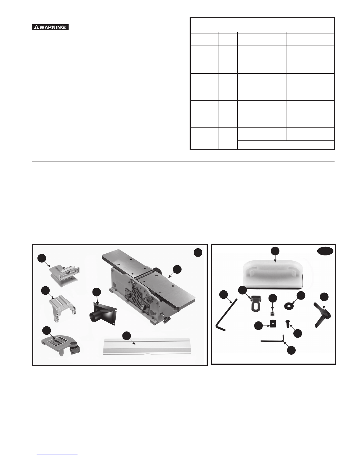
CARTON CONTENTS
4
5
3
1. Jointer
2. Fence
3. Cutterhead Guard
4. Fence Sliding Bracket
5. Fence Mounting Bracket
6. Vacuum Hose Adaptor
7. Push Blocks - (2)
6
4
7
4A
1
14
15
13
8
9
12
2
10
11
8. M8 Flat Washer
9. Spring Loaded Lock Handle
10. M6 x 1 x 16 mm Button Head Screw - (6)
11. 5/32 Hex Wrench
12. Special Nut
13. M6x1 Square Nut - (2)
14. 7/64 Hex Wrench
15. Cutterhead Lock
5
UNPACKING AND CLEANING
NOTICE
Carefully unpack the machine and all loose items from the
shipping container(s). Remove the rust-preventative oil from
unpainted surfaces using a soft cloth moistened with mineral
spirits, paint thinner or denatured alcohol.
Do not use highly volatile solvents such as
gasoline, naphtha, acetone or lacquer thinner for cleaning your
machine.
After cleaning, cover the unpainted surfaces with a good quality
household floor paste wax.
ASSEMBLY
To reduce the risk of injury, turn unit off
and disconnect it from power source before installing and
removing accessories, before adjusting or when making
repairs. An accidental start-up can cause injury.
ASSEMBLY TOOLS REQUIRED
•Two hex wrenches (supplied)
ASSEMBLY TIME ESTIMATE
Assembly for this machine takes approximately 1 hour.
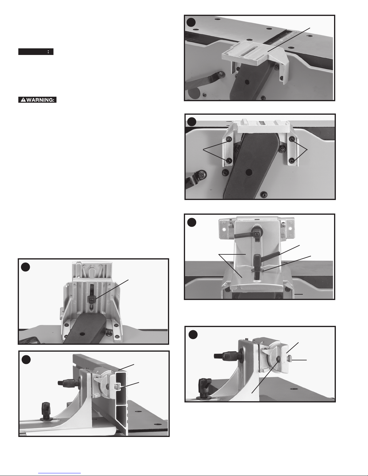
FENCE
1. Assemble the fence mounting bracket (A) Fig. 5 to the
jointer base using the four M6x1x16 mm button head
screws (B) Fig. 6.
2. Assemble the fence sliding bracket (C) Fig. 7 to mounting
bracket (A) using the lockhandle (D), M8 flat washer (E) and
special nut (F) Fig. 8.
3. Insert a M6x1x16 mm button head screw (G) Fig. 9 through
fence tilting bracket (H) and thread a M6 x 1 square nut (J)
onto threaded end of screw (G). DO NOT COM PLETE LY
TIGHTEN SCREW (G) AT THIS TIME. Assemble screw
and square nut to opposite end of tilting bracket in the
same manner.
4. Slide groove of fence (L) Fig. 10 over square nuts (J).
5
A
6
B
B
7
D
C
E
8
10
F
A
9
L
H
J
J
G
6
11
NOTICE
12
L
G
G
M
13
A
15
A
B
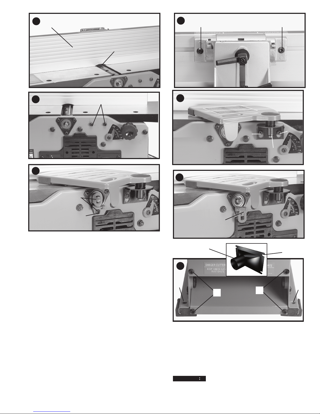
5. Position fence (L) Fig. 11 so that rounded section (M) on
bottom of fence is over cutterhead opening.
6. Tighten two screws (G) Fig. 12 using included hex
wrench.
CUTTERHEAD GUARD
1. Locate the two M6x1x12 mm button head screws (A) Fig.
13 in front side of jointer base. MAKE SURE THEY ARE
NOT COMPLETELY TIGHTENED AT THIS TIME.
2. Slide cuttinghead guard's mounting bracket (B) Fig. 14
onto the two screws (A). Make sure cutterhead guard is
touching the fence and tighten the two screws (A).
CUTTERHEAD LOCK
Assemble cutterhead lock (A) Fig. 15 to the front side of the
jointer base, using the M6x1x12 mm button head screw (B).
NOTE: The cutterhead lock (A) is to be engaged with the
cutterhead shaft (Fig. 15) Only when setting knives. All other
times, the cutterhead lock (A) should be disengaged from the
cutterhead (Fig. 16).
FASTENING JOINTER TO SUPPORTING SURFACE
If during operation, there is any tendency for the jointer to tip
over, slide or "walk" on the supporting surface, the jointer must
be secured to the supporting surface. Four holes (two of which
are shown at (R) Fig. 20), are provided for this purpose.
14
A
A
B
16
A
V
U
20
R
S
VACUUM HOSE ADAPTER
A vacuum hose adapter (V) Fig. 20 is supplied with the jointer to
help connect it to a standard 2 inch vacuum hose. To assemble
the adapter:
1. Remove two screws (S) Fig. 20. Loosen screws (T).
2. Slide adaptor's slots (U) under loosened screws (T).
3. Tighten screws (T) when adaptor (V) is in proper location.
4. Replace and tighten screws (S).
Do not install this dust chute unless you will be
using a dust collector.
T
R
7
OPERATION
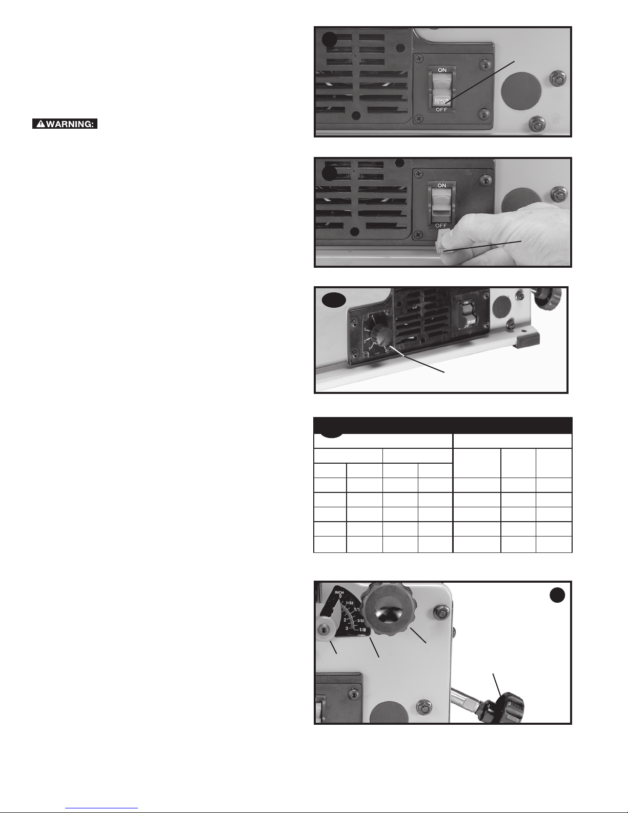
STARTING AND STOPPING JOINTER
1. The on/off switch (A) Fig. 21 is located on the front of the
jointer. To turn the machine "ON", move switch (A) up to
the "ON" position.
2. To turn the machine "OFF", move the switch down to the
"OFF" position.
21
A
position before plugging in the power cord. In the event of
a power failure, move the switch to the "OFF" position. An
accidental start-up can cause injury.
LOCKING SWITCH IN THE "OFF" POSITION
IMPORTANT: When the machine is not in use, the switch
should be locked in the "OFF" position to prevent
unauthorized use. To lock the machine, grasp the switch
toggle (B) and pull it out of the switch (Fig. 21). With the switch
toggle (B) removed, the switch will not operate. However,
should the switch toggle be removed while the
running, the machine can be turned "OFF," but cannot be
restarted without re-inserting the switch toggle (B).
VARIABLE SPEED CONTROL
Your jointer is supplied with variable speed control (A) Fig. 23A
that enables you to operate the machine at cutterhead speeds
between 6,000 and 11,000 RPM. Speed indicators of 1-2-3-4
and 5 are provided on the speed dial. When the pointer on
the speed knob is pointing to 1, the cutterhead speed will be
6,000 RPM; 2 – 7,250 RPM; 3 – 8,800 RPM; 4 – 9,750 RPM;
and 5 – 11,000 RPM.
SPEED SELECTION CHART
Use the speed selection chart (Fig. 23B) to determine the
proper setting for your workpiece.
NOTE: For convenience, make a copy of this chart and post it
on or near the machine.
DEPTH OF CUT ADJUSTMENT
The jointer can be set to cut any depth from a very thin shaving
to 1/8 inch (3.2 mm) deep. A dual English/Metric scale (A)
Fig. 24, and pointer (B) are provided to indicate the depth of
cut. To adjust for depth of cut, loosen lock knob (C) and turn
adjusting knob (D) clockwise to lower and coun ter clock wise to
raise the infeed table. Raising the infeed table decreases the
depth of cut, while lowering it will increase the depth. After the
infeed table is at the desired setting, tighten lock knob (C).
NOTE: For best results, final positioning of the infeed table
should always be made from the bottom to the up position.
Make sure that the switch is in the "OFF"
jointer
is
22
B
23A
A
23B
FROM TO PLASTICS SOFT
inches mm inches mm
0 0 1½ 38.1 1 1 1
1½ 38.1 2½ 65.5 2 2 3
2½ 63.5 3¼ 82.5 3 3 4
3¼ 82.5 4 101.6 --- 4 5
4 101.6 6 152.4 --- 5 5
SPEED SELECTION CHART
CUTTING WIDTH CONTROL SETTING
WOOD
HARD
WOOD
24
C
B
A
D
8
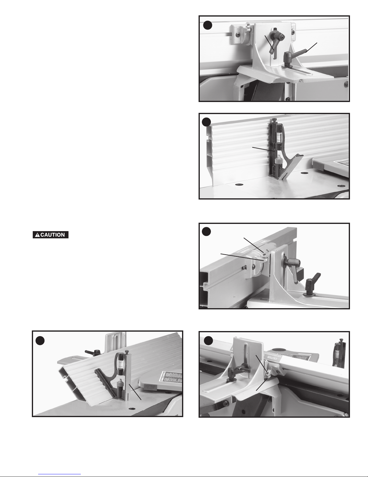
FENCE ADJUSTMENTS
The fence can be moved across the table and can be tilted up
to 45 degrees, as follows:
1. To move the fence across the table, loosen lock lever (A)
Fig. 25, slide the fence to the desired position on the table
and tighten lever (A).
NOTE: Lock lever (A) is spring loaded and can be repositioned
by pulling up on the lever and repositioning it on the nut located
underneath the lever.
2. To tilt the fence, loosen lever (B) Fig. 25, and tilt the fence
to the desired angle. Then tighten lever (B).
NOTE: Lever (B) is spring loaded and can be repositioned by
pulling out on the lever and repositioning it on the nut located
un der neath the lever.
3. The fence features adjustable positive stops at the most
used fence positions of 90 degrees and 45 degrees to the
right. To check and adjust the positive stops, proceed as
follows:
4. Place a square (C) Fig. 26, on the table with one end of the
square against the fence as shown. Adjust the fence until it
is exactly 90 degrees to the table.
5. Using supplied hex wrench, turn set screw (D) Fig. 27 until
it contacts stop (E).
6. Using a square (C) Fig. 28, tilt the table to the 45 degree
position and make sure the fence is 45 degrees to the
table. Adjust the fence if necessary.
7. Using supplied hex wrench, turn set screw (H) Fig. 29, until
it contacts stop (G).
8. These positive stops enable you to rapidly position the
table to the 90 and 45 degree settings.
Make sure the fence is in level contact with
the surface of the outfeed table.
25
B
A
26
C
27
D
28
E
29
H
G
C
9
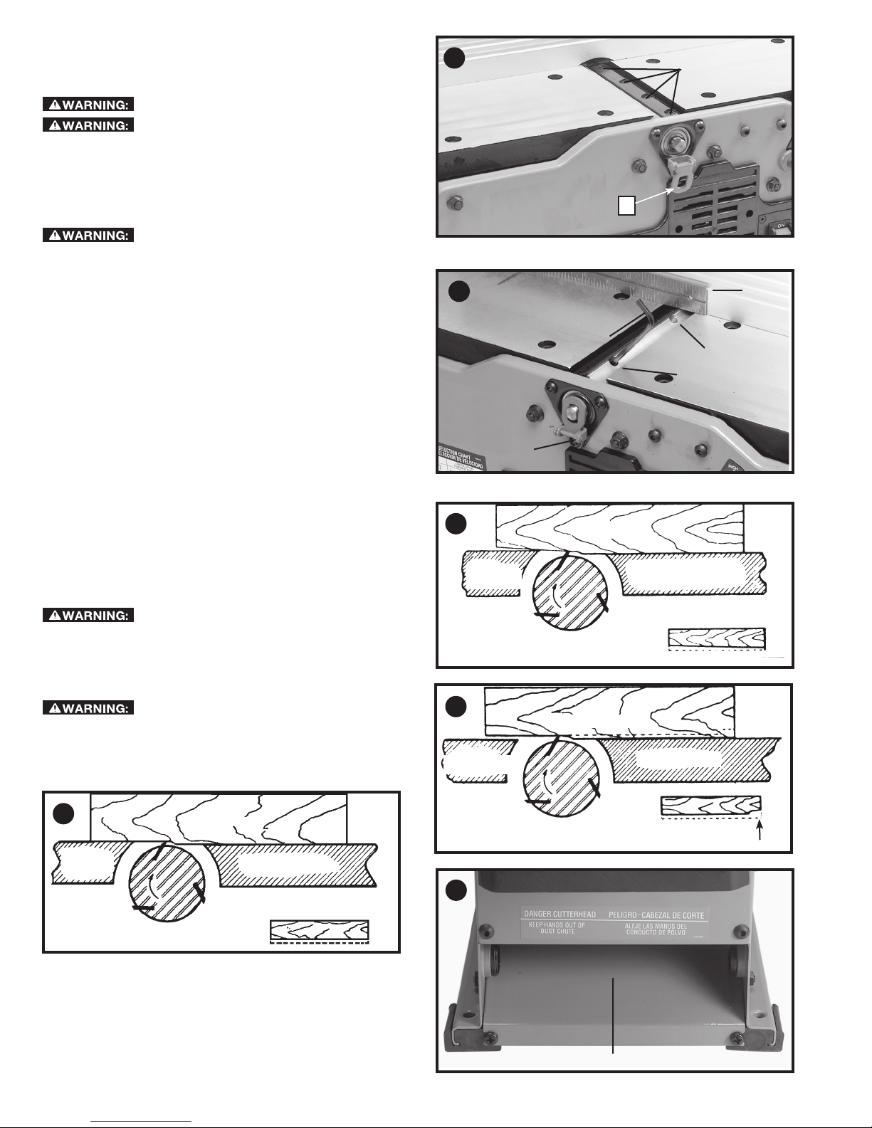
ADJUSTING KNIVES
When it becomes necessary to replace or adjust the knives
due to replacement or wear:
The knives are sharp.
Disconnect machine from power source.
1. Remove cutterhead guard.
2. To replace a knife, disengage the cutterhead lock (A) Fig.
30. Rotate cutterhead, loosen four screws (B) and remove
bar and knife. Insert new knife and replace bar and slightly
tighten four screws (B).
30
B
A
come in contact with the knives.
Be extremely careful that your hands do not
3. To adjust the knives, make sure the cutterhead lock (A)
Fig. 30 is not engaged. Make sure screws (B) are not overly
tightened. Loosen each one half turn or only enough so
knife can slide between locking plate and cutterhead.
4. Rotate cutterhead and engage cutterhead lock (B) Fig. 31,
on cutterhead shaft as shown. This will position knives for
proper adjustment to the outfeed table.
5. Place a straight edge (D) Fig. 31, on the outfeed table
extending out over the knife as shown. Using wrench (C)
supplied, turn screw (E) until knife just touches straight
edge. Adjust knife at near end of cutterhead in the same
manner turning screw (F). Tighten four screws (B) Fig. 30,
after adjustment is made.
NOTE: Make sure cutterhead lock (B) is disengaged after
adjustment is completed and replace cutterhead guard.
6. If the knives are set too low, the result will be as shown in
Fig. 32, and the finished surface will be curved.
7. If the knives are set too high, the work will be gouged at the
end of the cut, as shown in Fig. 33.
8. As a final check, run a piece of work slowly over the knives
for 6 to 8 inches (152 to 203 mm). The wood should rest
firmly on both tables as shown in Fig. 34, with no open
spaces under the finished cut.
Make certain that all knives are securely
fastened in cutterhead before turning on power.
CHIP AND DUST CHUTE
A chip and dust chute (A) Fig. 35 is provided on the outfeed end
of the jointer base for efficient chip removal.
Keep hands out of chip and dust chute at
all times.
31
B
32
OUT-FEED
TABLE
KNIVES
SET TOO LOW
33
D
C
E
F
MATERIAL
IN-FEED TABLE
CUTTER
MATERIAL
34
OUT-FEED
TABLE
KNIVES AT
MATERIAL
IN-FEED TABLE
CUTTER
CORRECT HEIGHT
KNIVES
SET TOO HIGH
35
10
OUT-FEED
TABLE
IN-FEED TABLE
CUTTER
GOUGE
A
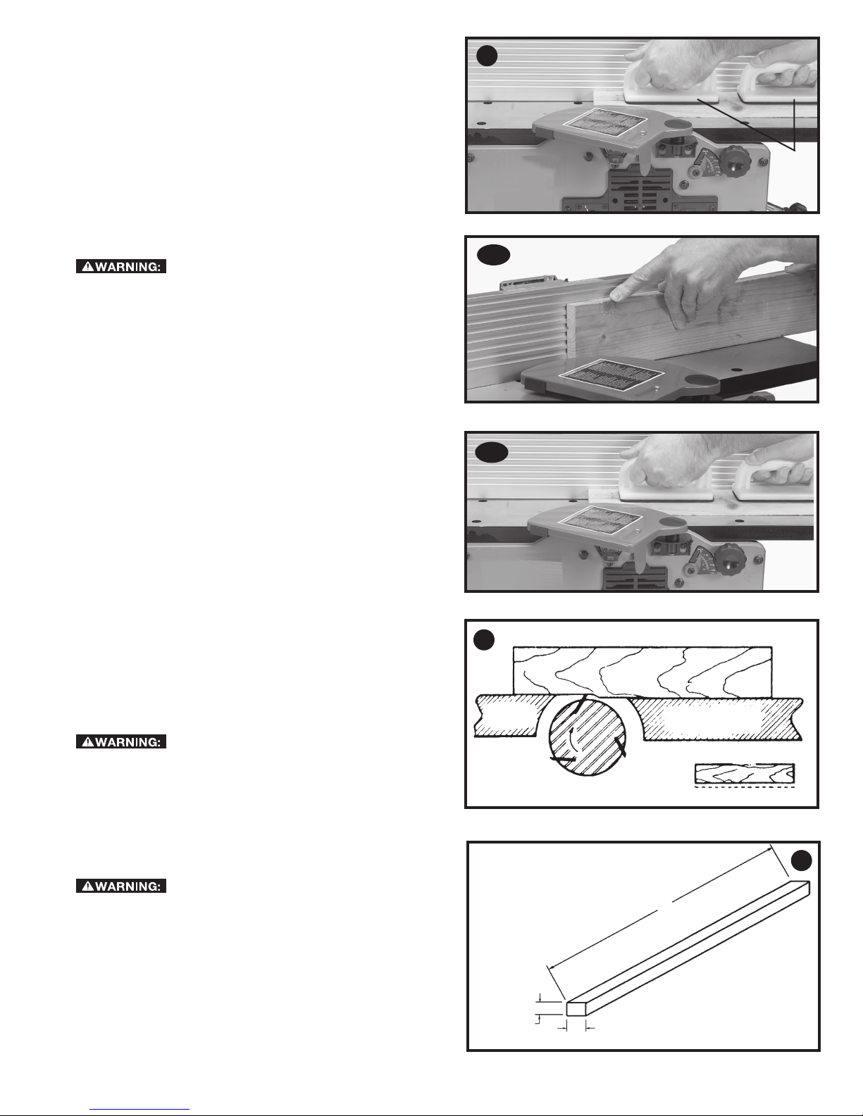
PUSH BLOCKS
A set of push blocks (A) Fig. 36 is supplied with your jointer and
should be used whenever possible to minimize all danger to
your hands. Fig. 36 illustrates using the push blocks properly.
MACHINE USE
The following directions will give the beginner a start on jointer
operations. Use scrap pieces of lumber to check the settings
and to get the feel of the operations before attempting regular
work.
NOTE: The knives on the jointer will not wear evenly by feeding
the wood through the same spot on the table every time. Feed
the wood through the jointer at different spots on the table to
help eliminate uneven wear of the knives.
Always use cutterhead guard and keep
hands away from cutterhead. Use push blocks whenever
possible.
DEFINITION OF JOINTING, PLANING
1. JOINTING OPERATIONS – Jointing cuts or edge
jointing are made to square an edge of a workpiece.
The workpiece is positioned on the jointer with the
narrow edge of the workpiece on the infeed table and
the major flat surface of the workpiece against the fence,
as shown in Fig. 37A. The workpiece is moved from the
infeed table, across the cutterhead to the outfeed table.
2. PLANING OPERATIONS – Planing or surfacing are
identical to the jointing operation except for the position
of the workpiece. For planing, the major flat surface of
the workpiece is placed on the infeed table of the jointer
with the narrow edge of the workpiece against the fence,
as shown in Fig. 37B. The workpiece is moved from the
infeed table, across the cutterhead to the outfeed table.
Use push blocks when performing planing operations
whenever possible.
36
A
37A
37B
PLACEMENT OF HANDS DURING FEEDING
At the start of the cut, the left hand holds the work firmly
against the infeed table and fence, while the right hand pushes
the work toward the knives. After the cut is un der way, the new
surface rests firmly on the outfeed table as shown in Fig. 38.
The left hand should then be moved to the work on the outfeed
table, at the same time maintaining flat contact with the fence.
The right hand presses the work forward, and before the right
hand reaches the cutterhead it should be moved to the work
on the outfeed table.
Never pass hands directly over the
cutterhead.
JOINTING AN EDGE
This is the most common operation for the jointer. Set the
guide fence square with the table. Depth of cut should be the
minimum required to obtain a straight edge. Hold the best face
of the piece firmly against the fence throughout the feed as
shown in Fig. 37A.
Do not perform jointing operations on
material shorter than 10 inches (254 mm), narrower than
3/4 inch (19 mm), or less than 1/2 inch (12.7 mm) thick (refer
to Fig. 39).
PLANING WARPED PIECES
If the wood to be planed is dished or warped, take light cuts
until the surface is flat. Avoid forcing such material down
against the table; excessive pressure will spring it while
passing the knives, and it will spring back and remain curved
after the cut is completed.
38
MATERIAL
OUT-FEED
TABLE
CUTTER
MINIMUM JOINTING DIMENSIONS
10 inches (254 mm) MINIMUM
1/2 inch
(12.7 mm)
MIN I MUM
3/4 inch (19 mm) MIN I MUM
IN-FEED TABLE
39
11
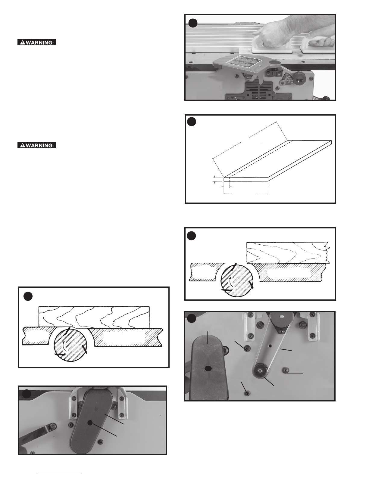
PLANING SHORT OR THIN WORK
When planing short or thin pieces, always use push blocks to
minimize all danger to the hands. Fig. 40, illustrates using the
Push Blocks properly.
Do not perform jointing operations on
material shorter than 10 inches (254 mm), narrower than
3/4 inch (19 mm), or less than 1/2 inch (12.7 mm) thick (refer
to Fig. 41).
DIRECTION OF GRAIN
Avoid feeding work into the jointer against the grain as shown
in Fig. 42. The result will be chipped and splintered edges. Feed
with the grain as shown in Fig. 43 to obtain a smooth surface.
TROUBLESHOOTING
For assistance with your machine, visit our website at www.
portercable.com for a list of service centers or call the help line
at 1-888-848-5175.
MAINTENANCE
To reduce the risk of injury, turn unit off
and disconnect it from power source before installing and
removing accessories, before adjusting or when making
repairs. An accidental start-up can cause injury.
BELT REPLACEMENT
When it becomes necessary to replace the belt on your jointer:
1. Remove screw (A) Fig. 44, using hex wrench supplied, and
remove belt guard (B).
2. Loosen three screws (C) Fig. 45, to release belt tension
and remove belt (D) from pulleys.
3. Assemble new belt to the cutterhead and motor pulleys.
Press down on motor pulley (E) Fig. 45, to tension belt and
tighten three screws (C).
NOTE: There should be approximately 1/4 inch (6.4 mm)
deflection in the belt (D) at the center span of the pulleys
using light finger pressure. The belt does not require excessive
tension to function properly.
4. Replace belt guard (B) Fig. 44.
40
41
42
MINIMUM AND
MAXIMUM PLANING
DIMENSIONS
10 inches (254 mm) MINIMUM
1/2 inch
(12.7 mm)
MINIMUM
(152.4 mm) MAXIMUM
WRONG FEED -
AGAINST THE
GRAIN
3/4 inch (19mm) MINIMUM
6 inches
MATERIAL
43
OUT-FEED
TABLE
44
CORRECT FEED - WITH THE GRAIN
MATERIAL
IN-FEED TA BLE
CUTTER
B
A
OUT-FEED
TABLE
45
IN-FEED TABLE
CUTTER
B
C
D
C
C
E
12
 Loading...