

Page 1
Instruction
manual
Model
BSV750
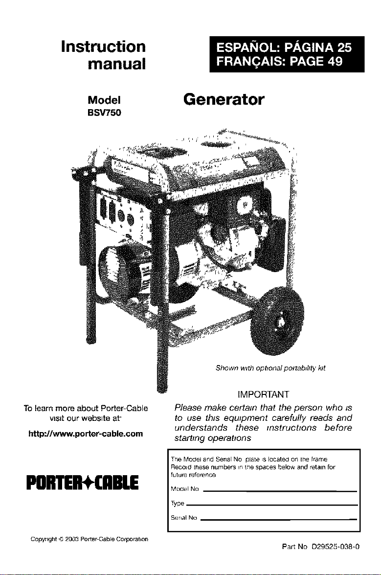
Generator
Shown with optional po/tab#/ty kit
To learn more about Porter-Cable
vls=t our webslte at'
http:Hwww.porter-cable.com
PORTEII*CABLE
Copyright ,_ 2003 PorterCableCotporahon
IMPORTANT
Please make certain that the person who is
to use this equipment carefully reads and
understands these instructions before
starting operations
The Model and SenaJ NO plate ts located on the [tame
Record these numbers _nthe spaces below and retain for
future reference
Model NO
Type
Senal No
Part No 029525-038-0
Page 2

• Please read and follow these instructions for proper use and maintenance.
• If you experience any problems and need assistance, please call us at our toll
free number 1-888-559-8550, Monday through Saturday, 8:00 a.m. To 6:00
p.m.C.S.T.
• If repair or service part purchase is required, our many Authorized Warranty
Service Centers are conveniently located and equipped to handle all in-
warranty and out*of-warranty service.
• For the location of the nearest Authorized Warranty Service Center call
1-888-559-8550, Ext. 2, 24 hours a day, 7 days a week.
• Retain sales receipt as proof of purchase for warranty service.
• Read and understand all safety warnings.
• DO not operate this unit until you have read and understand this Owners
Manual for Safety, Operation, and Maintenance Instructions.
• Do not operate this unit until you have read and understand the Engine
Owners Manual for Safety, Operation, and Maintenance Instructions.
Note: Photographs and line drawings used inthis manual are for reference only and
do not represent a specific model.
Read Operators ManuaJ, Do not operate equipmer_t until you have _ead
Instruotions_
on land covered with materials such as agricultural crops, forest, brush, grass, or other similar
items, then an approved spark arrester must be installed and is legally required in the state of
California, it is a violation of California statutes section 130050 and/or sections 4442 and 4443
of the California Public Resources Code, unless the engine is equipped with a spark arrester, as
defined in section 4442, and maintained in effective working order, Spark arrester are also
required on some U.S. Forest Service land and may also be legally required under other
statutes and ordinances,
operators Manual for Safety, Assembly, Operafion_ and Maintenance
This product may not be equipped with a spark arresting muffler. If the
product is not equipped and will be used around flammable materials, or
Engine exhaust contains chemicals known, in certain quantities, to cause
cancer_ birth defects or other reproductive harm.
D29525 2-ENG
Page 3
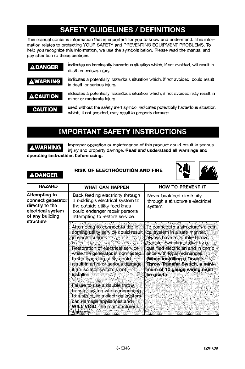
Thismanualcontainsinformationthatisimportantforyoutoknowandunderstand,Thisinform
mationrelatestoprotectingYOURSAFETYandPREVENTINGEQUIPMENTPROBLEMS, To
help you recognize this information, we use the symbols below, Please read the manual and
pay attention to these sections,
indicates an imminently I_tzardous situation which, if not avoided_ will result in
death or serious inju£4
indicates a potentially hazardous situation which, if not avoided, could result
in death or serious injury,
indicates a potentially hazardous situation which, if not avoided,may result in
minor or moderate injury
used without the safety alert symbol indicates potentially hazardous situation
which, if not avoided_ may result in property damage,
Improper operation or maintenance of this product could result in serious
operating instructions before using.
HAZARD WHAT CAN HAPPEN HOW TO PREVENT IT
Attempting to
connect generator
directly to the
electrical system
of any building
structure.
injury and property damage. Read and understand all warnings and
RISK OF ELECTROCUTION AND FIRE
Back feeding electricity through
a building's electrical system to
the outside utility feed lines
could endanger repair persons
Never backfeed electricity
through a structure's electrical
system.
attempting to restore service.
3-ENG D29525
Page 4
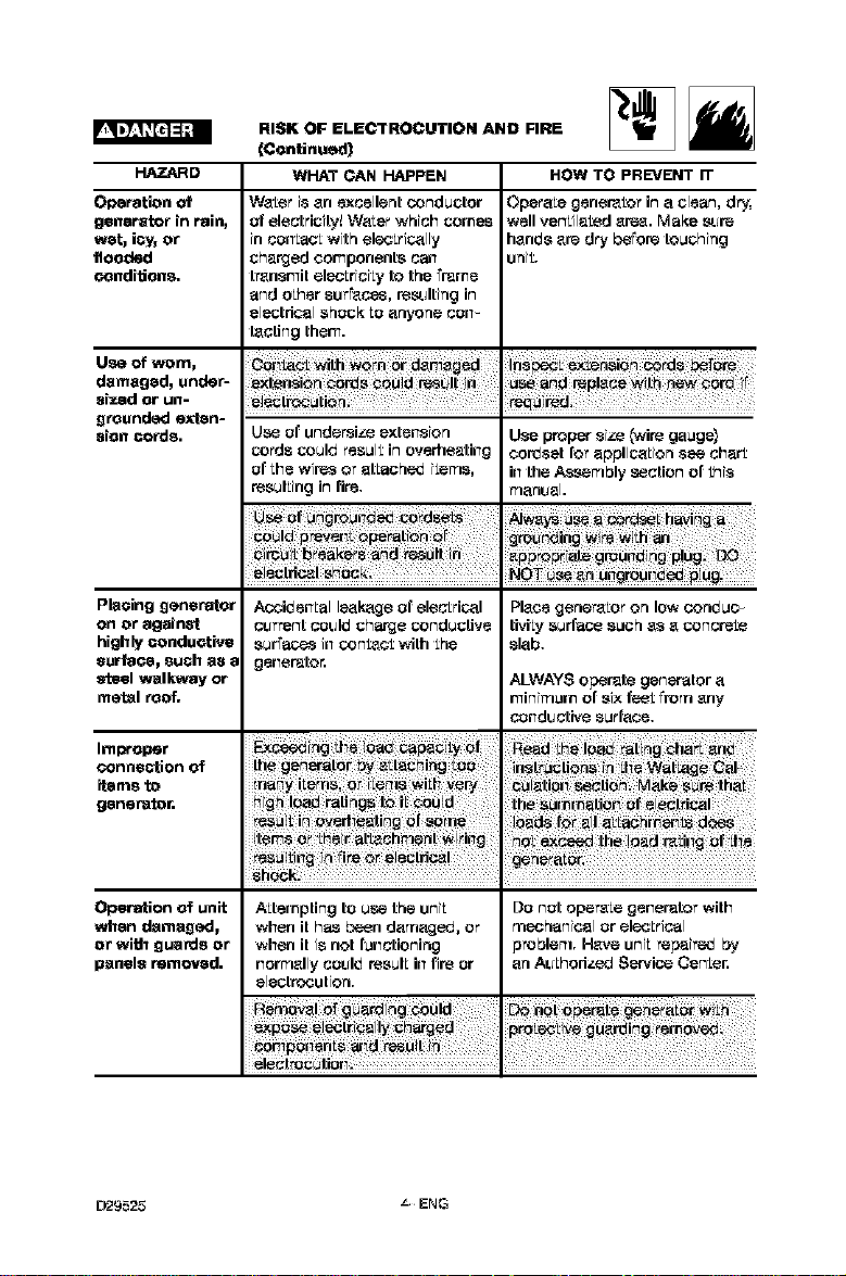
HAZARD
Operation of
generator in rain_
wet, iGy_or
flooded
conditions,
Use of worn,
damaged, undet-
si_.edor un-
grounded exten-
sion cords.
RISK OF ELECTROCUTION AND FIRE
(Continued)
WHAT CAN HAPPEN
Wa[er i8 an excellent conductor
t_felectricity!WaLer which comes
in conLac[ with ele_£rically
charged components ca_
transmit elsoLriciLy 1o the Frame
and o£her surfaces, resa;Iting in
electrical shock Loanyone co;t-
lacting them.
Use t_f undersize extension
cords could resul£ iR overhe_tkrg
t_f Live wire8 or stLaohe_ i[ert_8,
resulLing in fie.
Opera[e genera[or in a clean, dry,
well ver%il_[ed area. Make r_re
handsare dry before touching
uni£.
Use proper size (wire gauge}
cordsst for appli_[ion see char£
in the Assertlbly section of £his
f_lanlJ_l.
HOW TO PREVENT iT
Placing generator
on or against
highly conductive
surPaGel 8uGb a8 8
steel walkway or
metal roof.
Improper
conne_"tionof
Acciden[al leakage of elec£rical
cL;rrent coL;Id charge conductive
surfaces in con[ao£ with £he
generator.
i_ms to
generator.
Shock_ .
OpePstion of unit
when damaged,
or wi_ guards or
panels removed.
D29525 _ENG
A[te_npting to use the uni[ Do nt_t opera[e generator with
when it has been dar_'_aged,or r_'_sohanicalor elecLrical
when it is not functioning problert=. Have uni[ repeire_ by
norrt_ally co_;Id resul[ in fire or an AL;[horize_ Servico Cen£er.
electrooution.
Place generaLor on low conduc _
tiviLy surface such 88 a concre[e
slab.
ALWAYS operate generator a
minin=urn of six feel Fromany
co_dL_ctive sur[ace.
Page 5
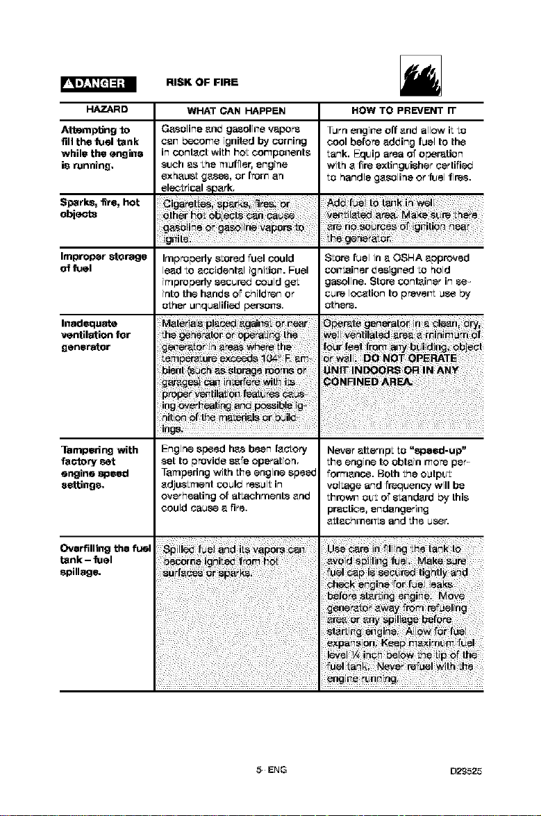
RISK OF FIRE
HAZARD WHAT CAN HAPPEN HOW TO PREVENT IT
Attempting to
fill the fuel tank
while the engine
is running,
G_soline _ed gasoline vapor@
can become ignited by coming
in conl_ct wiLhhoLcornpo_vents
such as £hef_tuffler, engine
exhaust ge.see, or from an
Turn engine off and allow if [o
cool before adding fuel to the
tank. EqL_iparea of operation
with a fire extingL_isher certified
[o handle gasoline or &_elfires.
ele_£rical spark.
Sparks__m, hot
obi_ta
Improper _oPage
of fuel
InadeClUata
ventilation for
generator
Tampering with
fac'tary set
engine speed
settings,
Overfilling the fuel
tank - fuel
@pillage.
Improperly stored fuel could
lead [o accidental ignition. Fuel
inlp_pedy secur_ could ge£
into the hands oFchildren or
t_£herunqualified persons.
{_ ;f65r feet from _i_ bLiilair,_ _5 #ci
Store fuel in a OSHA approved
container designed [o hold
gasoline. Store conl_iner in se-
cure location to pre,.'en[ use by
t_thers.
W_!lver=tilatsda_a _ ini_i_m _f
#ONF!NED A@_
ing _v_i!i_ii_g _5_ _ib!_ i_
Engine speed h_s been fac[ory
set to provide 8_fe operation.
Tampering with Liveengine speed
adjus£mer_t could resul£in
overheating of at_achnler_L'_and
could cause a rite.
Never _Eer_lpL LO "speed-up"
Live engine 1o obtain more per-
forr_lanoe. Both the outpL_£
voltage and FreqL_ency will be
thrown oL_£of 8_andard by this
practice, endangering
_£tach_nenLs and Live user.
_n_o _ _=
5ENG D2£525
Page 6
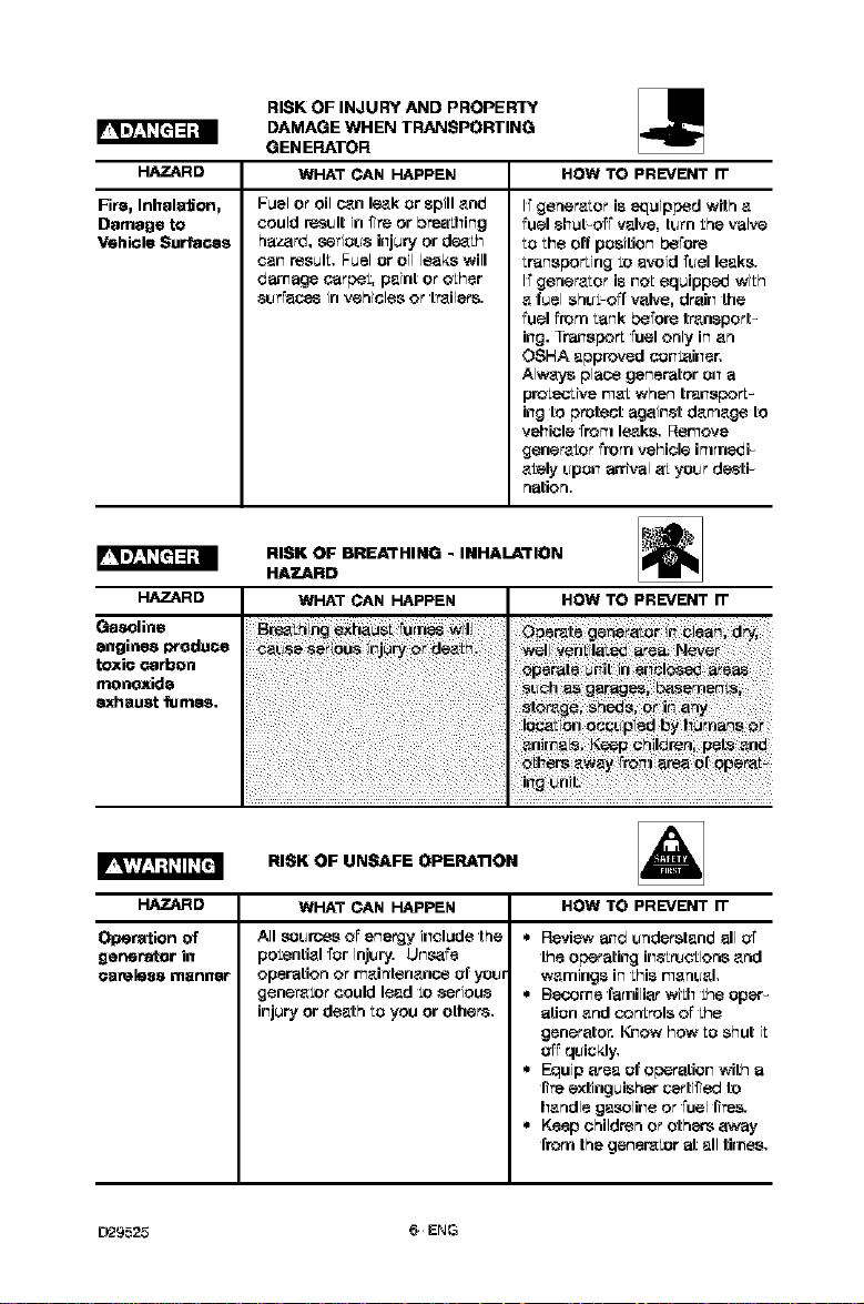
RISK OF INJURY AND PROPERLY
DAMAGE WHEN TRANSPORTING
GENERATOR
HAZARD WHAT CAN HAPPEN HOW TO PREVENT IT
Fire, Inhala_onj
Damage to
Vehicle Surfaces
Fuel or oil c_n le,_kor spilland
could r_sL_ltin fire or breaLhing
hazard, _erioL_sinjury or de,_th
can resulL Fuelor oil leaks will
damage carpet, paint oroLher
8L_rrace_in vehicles or Lrailers.
I_generaLor is equipped wiLh a
fuel 81_ut-oT_valve, tl._rnthe valve
Lo¸Liveoff position he,re
LransporLing[o avoid _el leaks.
I_gerler_Lor is noLequipp_ with
_L¸fuelshl._orl "vaive, dr;:ti_the
fuel from ¸Lankbefore transport-
ing. Tn_sporL fuel orlly in arl
OSHA approved conLaine_
AIw_L_ place generator o_ a
proLecLive rn_Ltwhen trades,fL-
ing to p_tect against darTlageto
vehicle frorTi le-_ks.Remove
gener_Lor from vehicle irTimedi-
_[ely L_ponarrival aLyoL_rdesti-
riatiori.
RISK OF BREATHING - INHALATION
HAZARD
HAZARD
WHAT CAN HAPPEN HOW TO PREVENT IT
Gasoline
engines I_Odu_e
toxic carbon
monoxide
exhaust fumes,
I_'_!1_ ;]; II_[_
RISK OF UNSAFE OPERATION I
HAZARD WHAT CAN HAPPEN HOW TO PREVENT IT
Operation of
generator in
€endless manner
All so_rces o7energy include the
potential _or inj_ry. Un_re
operatiori or rnairltenance of _l._f
genera[or could lead [o _eriou_
injuryor de_th Loyou or others.
,, Review =_d _nderstand all o_
the o_rati_g i_trL_tio_s a_d
warnings in¸tHisn_a_L_al.
,, Become _miliar with the oper_
aLiona_d _trols o7the
gen_rato_ I_ow How Loshut iL
o77qL_ickl_
* Equip area of operation with a
fi_eextinguisher _rtified to
handle gasolineor fuel fi_es.
* Keep childre_or othersarray
¸from the generator at all times.
D29525 6ENG
Page 7
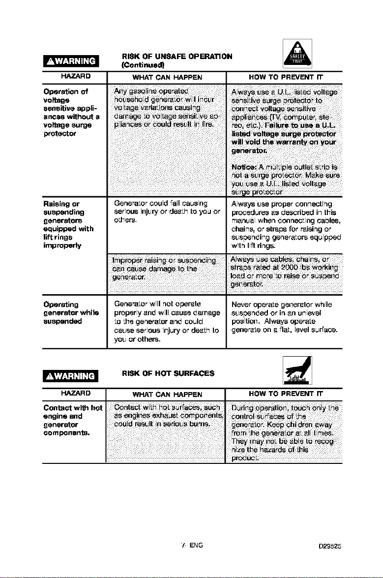
HAZARD
Operationof
voltage
sensitiveappli-
anoeswithouta
voltagesurge
prote_or
RISK OF UNSAFE OPERATION
(Continued)
WHAT CAN HAPPEN
HOW TO PREVENT IT
Raising or
suspending
generator8
equipped with
lift rings
improperly
Operating Genera[or will not operate Never opere[e ge_erator while
generator while properlyan_ will c_use _arnage suspsn_ed or inan unlevel
suspended [o LivegenereLor an_ could positio_. Always opereLe
HAZARD WHAT CAN HAPPEN HOW TO PREVENT IT
GeneraLorcould _all causing
serious ir=jup!or de4_Lhto you or
o[l_ers.
cause serious i_jury or de4t£hto gener_[e on a riM[, level surface.
you or others.
RISK OF HOT SURFACES
AIw_ t_8_proper conn_chg
procedures as desodpsd in this
rr=anualwhen conneoLing cables,
chains, or straps for r_ising or
suspsnding genera[ors equipped
with Ii_tdngs.
co.ta_ _ _of
engine and _ _rl_iii_ exha_i _o_pbii_r=_
components.generat°r i _Oe_
/ENG D2£525
Page 8
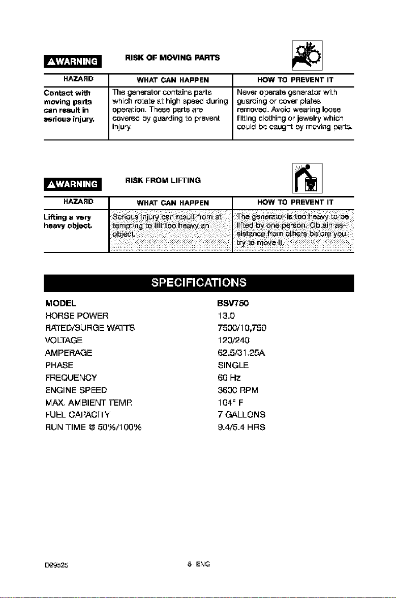
Conta_twi_
movingparts
canresultin
seriousiniulry,
HAZARD
Lifting a very
heavy object.
RISK OF MOVING PARTS
1he gsnerdtor conl_ins p_trts
which roLaLe _L high speed d_ring
oper_tLion. Thee p_zrl_ _tre
covered by g_arding Lo prevent
injury, WHAT CAN HAPPEN
RISK FROM LIFTING
HOW TO PREVENT IT
Never operate gener_tLor wiLh
gL_arding or cover plates
remov_,d. Avoid wearing loo,se
filling cloLhing or jewelry which
could be c_ught by rrovil_g parLs.
MODEL
HORSE POWER
RATED/SURGE WAll'S
VOLTAGE
AMPERAGE
PHASE
FREQUENCY
ENGINE SPEED
MAX, AMBIENT TEMP
FUEL CAPACITY
RUN TIME @ 50%/100%
D29525 8ENG
BSV750
13.D
7500/10,750
120/240
62.5/31,25A
SINGLE
60 Hz
3600 RPM
104_ F
7 GALLONS
9.4/5.4 HRS
Page 9

Read this manual. Do not attempt to operate equipment
until you have read this Manual for Safety, Operation, and
Maintenance Ins_'uctions.
NOTE: This manual is a general manual. Information in this manual may or
may not pertain to your model. Please read carefully.
NOTE: Left and right describes the location of a part with the operator
facing the outlet panel,
REMOVE GENERATOR FROM CARTON
. Open carton fromtop.
. Cut carton along dotted lines.
. Removeall carton inserts.
. Removegeneratorthrough openingin
carton.
. Removeshippingblock(s)from under the
gen head. Unscrew boltls } and remove the
shippingblock(s). It is very important that
this is removed before starting your
generator.
. !If equipped} See portability Kit instructions
to assemble the portability k_t.
OTHER LOOSE PARTS
1. Oil is supplied, see engineoperators manual for correct procedure to add oil
and fuel to engine.
2. The Iook_ngplugs maybe used when needed or required.
i
The locking plugs are to be installed and/or used in
accordance with appropriate local electrical code
regulations. Refer to instruc_ons enclosed with each plug for proper
ins_ll_ion.
3. 12V DO cables to be used with the 12V DC outlets. See Operation section.
IMPORTANT: B_ore any attempt to _art your generator be sure to check engine
oil (See Engine Operator's manual)
GROUNDING THE GENERATOR
A grounding lug issupplied with the generator for
use when requiredby local electrical ordinances.
Referto article 250 of the National Electrical Code
to olari_/any needed grounding information. Your
local eleatno company or a certified electrician
shouldbe able to help you with this information.
9ENG D2_525
Page 10

TYPICAL INSTALLATION OF BATTERY
. Recommended Batteryfor Electnc Start: 12V - 45 A H. or 210 CCA (Cold
Cranking Amps)
Purchase battery and battery hardware separately, not included with unit.
_. Place battery in Packwith terminals facing to-
wards generator head.
2. Place battery bracket (A) over battery as
shown in Figure (opposite battery terminals),
3. Place 'L' bolt (B) through top and bottom
brackets and securewith wing nut (C).
4,
Locate the solenoidon the left side
of the unit.
5.
Remove the nut from the solenoid
poet and place one end of the posi-
tive (red) battery cable onto the
poet. Reassemble nut and tighten
securely.
Lawn & Garden batteries can
come in two terminal _ -- _ -_- []
configurations. The Positive (+) and NegaBve (-)
terminals can be oriented so that _ey are +/-
or -/+, See Figure. In the unlikely event th_ the
battery terminals are unmarked, we
recommend that you return the battery to the
retailer for exchange for a properly marked
battery or let an authorized service center inet_ll the b_'_teryfor you. Failure
to connect the battery properly can possibly cause bodily injury. In addition,
extensive engine electrical damage not covered under warranty can result.
6. Attach the other end of the positive
Ired) battery cable to the positive 0)
terminal on the battery.
TO Prevent sparks
connect the red
IMPORTANT: See caution before
connecting cable to battery.
_-t e_ Cable
_osiBve) cable to the positive (+)
terminal before connecting the black
negative cable,
7. Attach one end of the negative
Iblack) cable to the negative (-)
terminal on the battery.
8. Attach the other end of the negative
(black) cable to the frame as shown,
Install the star washer between the
cableand the frame.
D'29525 10 ENG
Page 11

OBTAINING ELECTRICITY FROM THE GENERATOR
There are baalcally 2 ways to obtain electricity from a generetor:
1. Use of extension cords directly from the generetor to the appliance, lights,
tools, etc.
2. Use of a double-throw transfer switch installed directly to the main electdc._l
supply outalde of house.
EXTENSION CORDS
When using an appliance or tool at a consider_abledistance from the generator, a
3-wire extension cord that has a 3-blade groundingplug and a 3-alot receptacle
that accepts the tool's plug MUST be used in orderto reduce the risk of
electricalshock. A cord of adequate size must be used. Using the following chart
to determine the minimum wire alze required.
Extension Cord Wire Gauge Chart
Cord Wire Gauge
Length Size Amperage
0 to log ft. 12 ga. *Up to 20 amp draw
0 to log ft. 10 ga. Up to 30 amp draw
*NOTE: When amperage exceeds 20 amp; a 12 gauge sxtenalon cord should
not be used for long distances.
An extension cord that is hot to the touch is overloaded.
Repair or replace damaged extension cords immediately.
DOUBLE THROW TRANSFER SWITCH
I_,_"_"_11 Pctential hazards e×is_when a portableelectdc gener_atoris
connected to the main electrical supply coming into the house.
It is at that point that the clerical generator could feed back into the utility
company's system c._usingpossible electrocution of workers who are repairing
the electricallines.
TOavoid back:feeding of electricity into utility systems, a double-threw transfer
switch must be installed between the generetor and utility power. The Double-
Threw Transfer Switch shouldbe installed by a licensed electrician and in com-
pliance with all state and local electrical codes. I_/hen installing a Double-
Throw 1PansferSwitch, a minimum of 10 gauge wiring must be used.)
The electrician shouldalso install a sub-panel to isolate the circuitsyou would
want to use during an emergency or electric.al power outage. Your generator will
not be large enoughto handle the load of all the lights, appliances, _ etc. at
one time. TOselect which items to tun during the electrical power outage, see
Wattage Calculation section in this manual,
1_ ENG D2_525
Page 12

KNOW YOUR GENERATOR
ReadthisGeneralManualand _,afe_ Rulesbeforeoperal_onofyourGenerator.
Comparethe f]lustratfoninyourpartsmanualwithyourgeneratorto familiarizeyourselfwith
the [coatlano_variouscorr_olsandaajustmerts.Saveall manualsforf_ure references.
GENERATOR CAPACITY
IMPORTANT:Exceedingthe _ed capacityofyourgeneratorcanresultinset,cos damage
toyour generatorandconnectedeleetdca[de_icss.SeetheWattageCalculationsectionin
thisrnanua[to assistyou in¢Jstsrmintng_heappliancesandtools thatcanbe runwiththe
wattagecabecityof yourgenerater.
CIRCUIT BREAI_RS
Eachreceptaclehasacircuitbrier to brot_;t the generatorfromovedoacJing.Ifthe circuit
bt_,kertrtp_,unblugallel_,_'rical[cadsfrom thegenerator. Letthe circuitbreakercool
down.Pushcircuitbrier bLntonto re_t.
LOW OIL PROTECTION
3"Yourgenerator engine is equipped with Low Oil Shutdown. Low Oil Shutdown
is a safety device designed to protect your engine from damage in the event the
oil level in the crankcase is low.
II'while the engine is running, the oil gets low, it will automatically shut itself
down and will not restart until the oil is added. If the oil is low before sta_-up,
the generator will not start until oil is added.
NOTE: The LOWOil Shutdown mechanism is very sensitive.YOUmust fill the
engineto the full mark on the dipstick: to inactivate this safety device.
OFF/RUN/START SWITCH
Placed in the STALE position to start engine and the OFF position to stop
engine. NOTE: When engine is running switchwill remain in the run position.
IDLE CONTROL
Choose the correct application.
1. For nomlal application such as power tools, small eleotIfc appliances, light
bulbs, and radios:
Place the idle control switch inthe ON position. Thegenerator willidle down
when there is no load. This lowers the engine noise, saves on
fuel consumption, and engine life.
Idling down IS NOT recommend on large motors (refIfgeretors,
freezers, etc) or voltage sensitive electronic equipment
!computsrs, televisions, etc). For these applications:
Place the idle controlswitch inthe OFF position.
L_
IL
D29525 12 ENG
Page 13

12V DC OUTLET
IMPORTANT: Allow generator to run at no load for 5 minutes upon each initial
start-up to allow engine to stabilize.
IMPORTANT: When _e unit is running the baf_terywill charge. DO NOT
connect the 12V DC cables to the genera/cor'ebattery.
To charge battery:.
1,
Using the 12V DO cables supplied,connectthe red positive _) 12V DC cable
to the battery s positive (_) terminal,
5,
Attach the other end of the red positive (_) 12V DO cable to
the generators positive _) 12V DC outlet,
3,
Connect the black negative (-} 12V DO cable to the batterY's
negative (-)terminal,
4,
Attach the other end of the black negative(-) 12V DO cable to
the generators negative (-} 12V DO outlet.
5,
Charge the batter/ according to battery or equipment manufacturer
recommendations,
BEFORE START UP
Thisgeneratorhas beenshippedfromthefactorywithoutoilinthe
crankcase.Opera'shgthe unitwithoutoilcan damage_e engine.
Alwaysch_k engineoil k_velbeforeeverystart.Runningengine
lowof oil oroutofoilcouldresultineadousdamagetothe engine.
FO]IOwthe stsp_listedbelowbeforestartinggenerator:
1. Oh_: asgtneoiL Referto theEr_gtneOperator'sManual_r _j_/
correctgradeBradquanta/of oil. _,
2. Check:fuel Is,tel. fill as required. Make suregenerator ts _ j
_urnedoffand has been el[c_vedtime to coo]down.Use
clean,fresh,regularunleadedgasolinewitha minimumof87
oota_e. Donotmixoilwith gasoline.
F,_.I:_,'I_'_ _1 Neverfill fuel tank cornPletely• RI'tonkto _/_
1/;2"belowthe bottomofthe fillorneckto
providespacefor fuel expansion.Wipeanyfuel spillagefrom
engiseand equipmentbeforestartingengine.
Neverfillfueltank indoors.Neverfill fuel tank whenengine is
runningor hot.DOnotsmokewhen fillingfeel tank.
Neverrunengineindoorsorin enclosed,poorventilated areas,en-
gineexhaustcontainscarbonmooo:dbe,an odorlessand deadly
gas,
3. Makesuregeneratorisgroundedinacoor_ancs_h local rer._uirements.
4. All s[eT,i'ricalloadsMUSTbe_iscenneoted.
5, The idle control switch Mu83r be in the OFF position,
Enginespeedhasbeenfactory setto providesafeoparagon.
Tamperingwith theenginespeedadjustmentcouldresultin over-
heatingof attachmentsand couldcause afire. Neverattemptto "speed-up" the en-
giseto obtainmoreparfoffnance. Bo'lhthooutputvoltageandfrequencywillbe
thrown out ofstanda_ bythisprac'dce,endangeringattachmentsandthe user.
YouMUSTunpluganyloadfromthe generatorbeforestarUngto
preventpermanent damageto anyappliances.
13 ENG D2_525
Page 14

TO START THE ENGINE
Never run engine indoors or in enclosed, poor ventilated
areas, engine exhaust contains carbon monoxide, an
odorless and deadly gas.
1+ Openthe fuel shut-off valve.
2+ Move the choke control located on the engineto the '_Choke"position.
NOTE; No choke is requiredon warm engines, make sure choke is in the
"RUN" position on warm engine starts.
3+ For Electric Start:Push OFP_RUN\STAF_Tswitch on control
panel to the "START" position to start engine. Hold in
'START' position no longer than 15 seconds per minute
when trying to start engine.Extended cranking can damage
the startermotor.
NOTE: When _e engine starts the OFF/RUN/SR'ART switch is released into
t_e RUN position.
For Recoil Start:Place OFF/RUN/START switch inthe RUN
position. Grasp handle on rope rewind slowly,Pull rope with
a rapid full arm stroke, Let rope rewind slowly. Repeat if _ !
nscs_ary.
4. _'_q_erlengil_e sl_rLs, gradLl_tlly inove the choke _o the NO Choke" position.
NOTE: IF ENGINE OIL LEVEL 18 TOO LOW, ENGINE WILL NOT START.
CHECK OIL LEVEL AND ADD IF NECES&ARY,
IMPORTANT: Allow generator to run at no load for 5 minutes upon each initial
start-upto allow engineand generator to stabilize,
[329525 14 ENG
Page 15

STOPPING ENGINE
1, Disconnect all electricalloads.
2, Turn OFFiRUNiST_T switch to "OFF' position.
g, Close fuel shut-off valve.
CONNECTING ELECTRICAL LOADS
1, Leeengine run and warm up for five minutes after starting with no electrical
load.
Connect loads in the following manner to prevent damage to equipment:
2, Connect inductive load equipment first, inductive loads consist of
refrigerators,freezers, water pumps, airconditioners,or small hand tools,
Connect the items that requirethe mast wattage ffrst. See Wattage Calcu-
lation Section in this manual,
3, Connect the lights next.
4, Voltage sensitiveequipment should be the last equipment connectedto the
generater. Plug voltage eensitive appliances such at TVS, VCR's, micro-
waves, ovens, computers, and cordlesstelephones into a UL listed voltage
surgeprotector, then connect the UL listed voltage surgeprotector to the
genemter.
Failure to connect and operate equipment in this sequence
can cause damage to equipment and will void the warranty
on your generator.
Follow the wattage calculation table in the Wattage Calculation section of
this manual. Overloading the generator will cause power fluctuations and
can damage equipment and appliances.
Porter-Cable Corporation will only be responsible for damage to
customer's equipment when the generator is determined to be defse_ive.
311_iedetermination will only be made by an authorized representative of
Porter-Cable Corporation and this decision will be final. Porter-Cable
Corporation reserves the right to inspect the electrical connections at the
customer's site of operation and teat the generator for proper operation
before any determination of liability is made. Failure to maintain the
equipment or wiring for inspection will void any claim for damages by the
customer. Porter-Cable Corporation will not be responsible for equipment
damaged as a result of voltage surges, improper operation or improper
installation of the generator.
15 ENG D2_525
Page 16

CUSTOMER RESPONSIBILrrlEs TABLE
MAINTENANCE TASK
Check oil level
Change oil
Clean Air Filter .Assembly
Check Spark Plug
Prepare Unit for Storage
Before Every 25
each Hours of
use Every
Season
X See Note 2
x
x
Prepare unit for storage if it is to remain
Every 50 Every 100
Hours of Hours of
Every Every
Season Season
See Note I
X
idle for more than 30 days.
Note 1: Change oil after firsttwo (2) operating hours and every 50 operating
hours thereafter, more often if operated inextreme dusty or dirty conditions.
Note 2: Check oil after 5 hours of operation.
GENERAL RECOMMENDATIONS
The warranty of the generator does not cover items that have been subjected to
operator abuse or negligence. To receive full value from the warranty, operator
must mai_ain the generator as instructed inthis manual.
ENGINE MAINTENANCE
Refer to the Engine Operator's manual for service and maintenance of the
engine.
GENERATOR MAINPENANCE
Your generator should be kept clean and dry at alltimes, The generator should
not be stored or operated inenvironmentsthat includes excessivemoisture,
dust or any corrosive vapors. Ifthese sub_ancas are on the generator, clean
with a cloth or soft bristle brush, Do not use a gardenhose or anythingwith
water pressure to clean the generator. Water may enterthe cooling air slots and
could possibly damage the rotor, statorand the internal windings of the gen
head.
GROUND FAULT CIRCUIT INTERRUPTER GFCI RECEPTACLE)
MONTHLY: For maximum protection against eleotricelshockthe GFCI should
be tested monthly,
To test:
1. Depress the TEST button. "me RESET button should extend. If the RESET
button does not extend, notify a DeVIIbiasAir Power Company Authorized
Warranty Service Center.
2. To restore power, depress the RESET button firmlyinto the GFCI unit until an
audible click is heard. If reset properly, the RESETbufton isflush with the
surface of the test button. When the button stays in, the bower is ON.
[329525 18 ENG
Page 17

If you are going to store your generator for more than 30 days, use the
following infon'natron as a gurde to prepare the generatorfor storege.
Never store generator with fuel in the tank indoors or in
enclosed, poorly ventilated areas, where fumes can reach
an open flame, spark or pilot light as on a furnace, wafer heater, clothes
dryer or other gas appliances.
ENGINE PREPARATION
1. Add fuel stabilizer to fuel tank to minimizethe formation of fuel gum
deposits during storage.
2. Run engine at lasst 10 minutes after adding stabilizerto allow it to enter the
fuel system,
3. Next shut off engine,
4. Disconnect the spark plug wire and remove the spark plug,
5. Add one tasspoon of oil through the spark plug hole,
6. Place mg over spark plug hole and pull the recoil afew times to lubricate
the combustion chamber.
7. I_eplace the spark plug, but do not connect the spark plug wire.
NOTE: If a fuel stabilizer isnot used, all gasoline must be drained from the tank
and carburetor to prevent gum deposits from forming on these parts and causing
possible malfunction of the engine.
GENERATOR
, Clean the generator as outlined in the Maintenance Section on this manual.
. Check that cooling airslotsand openings on generaterare open and
unobstructed.
BATTERY
. Store battery as dasonbed by the bsttery manufacturer.
NOTE: After storing battery for a long pedod of time it may lose its charge, If
the battery loses its charge, manually start the engine with the battery connect-
ed. The engine will recharge the battery as it runs.
lYENG D2_525
Page 18

IMPORTANT
Never exceed the rated capacity of your generator. Serious damage to the
generator or appliance could result from an overload,
1. Starting and running wattage requirements should always be calculated
when matching a generators wattage capacity to the appliance or tool,
2. Triers are two types of electrfcal appliances that can be powered by
your generator:
A. Items such as radios, light bulbs, television sets, and microwaves
have a "resistive load'. Starting wattage and running wattage are
the same.
B. Items such as refrigerators, aircompressors, washer, dryer, and
hand tools that use an electrical motor have an 'inductive load".
Inductive load appliances and tools require approximately 2 to 4
times the listed wattage for starting the equipment. This initial load
only lasts for afew seconds on start-up but is very important when
figuring your total wattage to be used.
C. Always start your largest electrfc motor first, and then plug in other
items, one at atime.
NOTE: On 120-volt loads the maximum starting wattage should NOT
exceed one half of the rated generator wattage, Example: a 5000 rated
wattage generator = 2500 maximum starting wattage.
DETERMINING WATTAGE REQUIREMENT'3
Before operating this generator list all of the appliances and/or tools that are
going to operate at the same time, _hen determine the starting wattage
requirements and the running wattage requirements by following example
and/or re#erto household wattage calculator.)
1. First total the running wattage of all appliances and/or tools that will be
operated at the same time,
Running Wefts
Example I:
Lights 100 Watts
Television 300 Watts
Slow Cooker 250 Watts
TOTAL =650 Watts
2. Next the starting wattages of any appliances and/or tools that will start and
stop durfng operation.
Runnina Watts Starting W_'ts
Example 2:
Small Refrigerator 500 Watts 2000 Watts
TOTAL =500 Watts 2000 Watts
0. The running wattage of examples 1 & 2 totals 1150 watts. The starting
wat_ge of the small refrigerator is 2000 watts which is 1500 watts more
than the running watts, Takethis difference of 1500 starting watts from the
refrigerator and add to the total runningwatts of 1150,
Example 3: 1500 Starting Watts
1150 RunninoWatts
TOTAL =2650 Total Watts
Generator must have a maximum capacity of at least 2650 watts.
[329525 18 ENG
Startina W_'ts
O
O
O
0
Page 19

STARTING WATTAGE REQUIREMENTS
1. Some applianoas and tools will list on the motor nameplate the starting
and running voltage and amperage requirements. Use the following
formula to oonvert voltage and amperage to wattage:
Volts X Amp -- Watts
Example: 120 volts x 10 amps -- 1200 watts
2. To determine the approximate starting wattage requirementfor most
applianoas and tools with inductive "typemotors, multiply the Wattage that
was oalculeted by 2 to 4 times to assure adequate generator capaoity. If
the nameplate information is not available use the values on the following
chart as a guide.
3. Remember that the starting and running wattage for rasistive loads are the
same. (Example: a 100 wart light bulb requires only 100 watts to start.)
Most resistive loads will be listed in wattage.
19 ENG D2_525
Page 20

HOUSEHOLD WATTAGE CALCULATOR
[ CAUTION !! ] [_°'_ ]
....................... [ ]
TOTAL
1
L _ , I___,___
_'FO R pROOLJ_ NOT
THI_ TOTAL VU_" DE LI_ -,NAN vOU_ CEH_pATcR PATH(;
A_'i'U_L I N Dr_IL_UAL
D_ HI_HER OR LO_'I_ R
WATTAGE RA'TING OF YOU R OENF_,ATOR I I
"It _S "p2_ALVI,_'_BE G'__'¢n_ "r_1_0t_R ;IO_S_;IO_ WA'_ E_
D'29525 20 ENG
Page 21

PROBLEM
Engine will not
start
1, Low on fuel or oil.
2. Ignition switch in "Off"
CAUSE
position.
3, Faulty spark plug,
4. Choke in wrong position.
5, Fuel shut-offvalve in
closed position
6. Unit loaded during start-
up.
7. Spark plug wire loose.
No electrical
Faulty receptacle.
output
Circuit breaker kicked
out,
Defective capacitor.
Faulty power cord,
GFCI switch breaker
kicked out,
Repeated 1, Overload
circuit breaker 2, Faulty cords or
tripping equipment
Generator 1, Generator overloaded,
overheating 2, Insufficient ventilation.
No auto idle 1, Faulty solenoid
2, Faulty idle control switch
3 Faulty windings in stetor
4, Faulty circuit board
5 Faulty wire harness
DC does not
1. Faulty rectifier
have power
with the
circuit breaker
depressed
2. Faulty windings instetor
3. Faulty wiraharness
CORRECTION
1, Add fuel or oil.
2. Turn to :'ON" position
3. Replace spark plug.
4. Adjust choke accordingly,
5, Open fuel shut-off valve.
6. Remove load from unit.
7. Attach wire to spark plug.
1, Have Service Center
replace,
2, Depress and reset.
3, Have Service Center
replace capacitor.
4, Repair or replace cord.
5, Depress and reset
1, Reduce load.
2, Check for damaged, bare,
or frayed wires on
equipment. Replace.
1, Reduce load.
2, Move to adequate supply
of fresh air,
1, Have Service Center
replace,
2, Have Service Center
replace,
a3. Have Service Center
replace,
4, Have Service Center
replace,
5, Have Service Center
replace,
1, Have Service Center
replace,
2, Have Service Center
replace,
3, Have Service Center
replace,
2 ENG D2£525
Page 22

iil;dbd=iB_ LT;I±I=]=_±I_ill _
PORTEI_(IIBLE
D2952_ 22ENG
Page 23

23ENG D2_525
Page 24

CALL 1-888-559-8550 TO FIND A LOCAL AUTHORIZED SERVICE CENTER
NEAR YOU FOR REPAIRS AND SERVICE PART PURCHASES
ENGINE OIL
WArrA
WIRING
ENGINE
Referto engineowner's manual for oil recommendations.
Most generatorsare equipped witha low-oil shutdown. If the oil
is low or if the Generator is not level, the enginewillnot start,
Contact an electrician for any wiring instructions. If wiring into a
house, a double-throw transfer switch and a heavy du_, cord
set must be used.
Do not adjust or attempt maintenance without consulting engine
manual or an authorized engine service center.
Allow the generator to run 5 minutes at no load for the engine
and the gen head to stabilize,
OPERATION
Make sure the adequate size of extension cord is used. Refer to
the Grounding Instructions/Extension Cord section of the
owners manual.
If the generator is operating equipment that is drawing half of
the rated watts it is considered 50% load. Using all of the rated
watts is considered 100% load,
I ALWAYS REFER TO THE MANUALS SUPPLIED WITH THIS UNIT I
[329525 24 ENG
I
 Loading...