

Porter-Cable BSV550-W Instruction Manual

Instruction
manual
IMPORTANT
Please make certain that the person who
is to use this equipment carefully reads
and understands these instructions before
starting operations.
Part No. A16596 03-22-06 Rev.0
®
FRANÇAIS: PAGE 23
ESPAÑOL: PÁGINA 47
To learn more about Porter-Cable
visit our website at:
http://www.porter-cable.com
Model
BSV550-W
Copyright © 2006 Porter-Cable
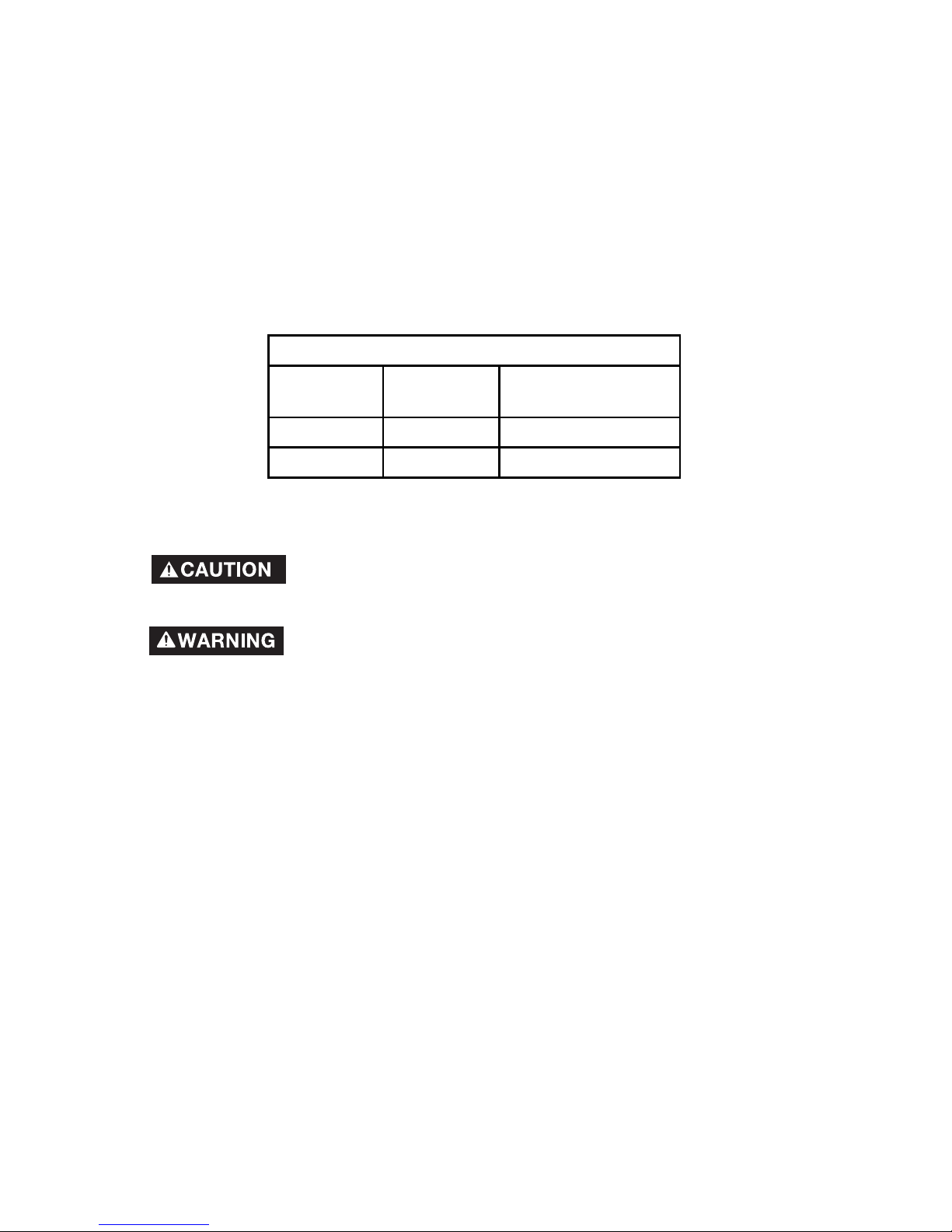
The Model and Serial No. plate is located on the frame.
Record these numbers in the spaces below and retain for
future reference.
Model No.
Type
Serial No.
Generator

2- ENG
A16596
Read Operators Manual. Do not operate equipment until you
have read operators Manual for Safety , Assembly, Op er a tion,
and Main te nance Instructions.
This product may not be equipped with a spark arresting
muffler. If the product is not equipped and will be used around
flam ma ble ma te ri als, or on land covered with materials such as agricultural
crops, forest, brush, grass, or other similar items, then an ap proved spark
arrester must be installed and is legally required in the state of California. It is a
violation of California statutes section 130050 and/or sec tions 4442 and 4443 of
the California Public Re sourc es Code, unless the engine is equipped with a spark
arrester, as defined in section 4442, and maintained in ef fec tive work ing order.
Spark arrester are also requir ed on some U.S. For est Service land and may also
be legally required under other statutes and or di nanc es.
Engine exhaust contains chemicals known, in certain
quantities, to cause cancer, birth defects or other
reproductive harm.
CONSUMER SAFETY INFORMATION
This manual contains in for ma tion that is im por tant for you to know and un der stand.
This in for ma tion re lates to pro tect ing YOUR SAFE TY and PRE VENT ING EQUIPMENT PROB LEMS. To help you r ec og nize this in for ma tion, we use the symbols
below. Please r ead the man u al and pay at ten tion to these sections.
indicates an imminently hazardous situation which, if not
avoided, will result in death or serious injury .
indicates a potentially hazardous situation which, if not
avoided, could result in death or serious injury .
indicates a potentially haz ard ous situation which, if not
avoided,may result in minor or mod er ate injury
used without the safety alert symbol indicates potentially
hazardous situation which, if not avoided, may result in
property damage.
SAFETY GUIDELINES / DEFINITIONS
TABLE OF CONTENTS
CONSUMER SAFETY INFORMATION
. . . . . . . . . . . . . . . . . . . . . . . . . . . . . . . 2
SAFETY GUIDELINES/DEFINITIONS
. . . . . . . . . . . . . . . . . . . . . . . . . . . . . . . .2
IMPORTANT SAFETY INSTRUCTIONS
. . . . . . . . . . . . . . . . . . . . . . . . . . . . 3-7
SPECIFICATIONS
. . . . . . . . . . . . . . . . . . . . . . . . . . . . . . . . . . . . . . . . . . . . . . .7
ASSEMBLY
. . . . . . . . . . . . . . . . . . . . . . . . . . . . . . . . . . . . . . . . . . . . . . . . . 8-11
OPERATION
. . . . . . . . . . . . . . . . . . . . . . . . . . . . . . . . . . . . . . . . . . . . . . . . 12-14
MAINTENANCE
. . . . . . . . . . . . . . . . . . . . . . . . . . . . . . . . . . . . . . . . . . . . . . . .15
STORAGE
. . . . . . . . . . . . . . . . . . . . . . . . . . . . . . . . . . . . . . . . . . . . . . . . . . . .16
WATTAGE CALCULATIONS
. . . . . . . . . . . . . . . . . . . . . . . . . . . . . . . . . . . 17-20
TROUBLESHOOTING GUIDE
. . . . . . . . . . . . . . . . . . . . . . . . . . . . . . . . . . . . .20
SERVICE . . . . . . . . . . . . . . . . . . . . . . . . . . . . . . . . . . . . . . . . . . . . . . . . . . . . . . .
21
ACCESSORIES
. . . . . . . . . . . . . . . . . . . . . . . . . . . . . . . . . . . . . . . . . . . . . . . .21
WARRANTY
. . . . . . . . . . . . . . . . . . . . . . . . . . . . . . . . . . . . . . . . . . . . . . . . . . .22
FRANÇAIS. . . . . . . . . . . . . . . . . . . . . . . . . . . . . . . . . . . . . . . . . . . . . . . . . . . 23-46
ESPAÑOL
. . . . . . . . . . . . . . . . . . . . . . . . . . . . . . . . . . . . . . . . . . . . . . . . . . 32-56
3 - ENG
A16596
IMPORTANT SAFETY INSTRUCTIONS
Improper operation or maintenance of this product could result
in serious injury and property damage. Read and understand
all warnings and operating instructions before using.
RISK OF ELECTROCUTION
AND FIRE
HAZARD WHA T CAN HAPPEN HOW TO PREVENT IT
Attempting to connect
gener a tor di rect ly
to the elec tri cal system of any building
structure.
Back feeding electricity through
a building’s electrical system
to the outside utility feed lines
could endanger repair persons
at tempt ing to re store ser vice.
Never backfeed electricity
through a structure's electrical
system.
Attempting to connect to the
in com ing util i ty service could
result in elec tro cu tion.
Restoration of electrical service
while the generator is connected
to the incoming utility could
result in a fire or se ri ous damage
if an isolator switch is not
installed.
Failure to use a double throw
transfer switch when connecting
to a struc ture's electrical system
can damage appliances and
WILL VOID the manufacturer's
warranty .
To con nect to a structure's electri cal sys tem in a safe manner ,
always have a Double-Throw
Trans fer Switch in stalled by
a qualified elec tri cian and in
compliance with lo cal or dinances. (When in stall ing a Dou ble-
Throw Trans fer Switch, a min imum of 10 gauge wiring must
be used.)
Operation of generator
in rain, wet, icy, or
flooded conditions.
Water is an excellent conductor
of electricity! Water which comes
in contact with electrically
charged com po nents can
transmit electricity to the frame
and other surfaces, re sult ing in
electrical shock to anyone contact ing them.
Operate generator in a clean,
dry , well ventilated ar ea. Make
sure hands are dry be fore
touching unit.
Use of worn,
damaged, un der sized
or un ground ed ex tension cords.
Contact with worn or dam aged
ex ten sion cords could result in
elec tro cu tion.
Inspect extension cords be fore
use and replace with new cord if
re quired.
Use of undersize extension
cords could re sult in over heat ing
of the wires or at tached items,
resulting in fire.
Use proper size (wire gauge)
cordset for application see chart
in the As sem bly section of this
manual.
Use of ungrounded cord sets
could pre vent operation of circuit
breakers and re sult in electrical
shock.
Always use a cord set having
a ground ing wire with an
appropriate grounding plug.
DO NOT use an un ground ed
plug. Use only outdoor rated
extension cords
4- ENG
A16596
RISK OF ELECTROCUTION
AND FIRE
(Continued)
HAZARD WHA T CAN HAPPEN HOW TO PREVENT IT
Placing generator
on or against highly
conductive surface,
such as a steel walkway or metal roof.
Accidental leakage of elec tri cal
current could charge conductive
surfaces in con tact with the
generator.
Place generator on low con ductiv i ty surface such as a concrete
slab.
ALW AYS operate generator a
min i mum of six feet from any
con duc tive surface.
Improper connection
of items to generator.
Exceeding the load capacity of
the gen er a tor by at tach ing too
many items, or items with very
high load ratings to it could result
in over heat ing of some items or
their attachment wiring re sult ing
in fire or electrical shock.
Read the load rating chart and
in struc tions in the Wattage
Cal cu la tion section. Make sure
that the sum ma tion of elec tri cal
loads for all at tach ments does
not ex ceed the load rat ing of the
generator.
Operation of unit
when dam aged, or
with guards or pan els
removed.
Attempting to use the unit when
it has been damaged, or when it
is not func tion ing normally could
result in fire or elec tro cu tion.
Do not operate generator with
me chan i cal or elec tri cal problem.
Have unit re paired by an Au thorized Ser vice Cen ter .
Removal of guarding could
expose elec tri cal ly charged
components and result in
electrocution.
Do not operate generator with
pro tec tive guarding re moved.
RISK OF FIRE
HAZARD WHA T CAN HAPPEN HOW TO PREVENT IT
Attempting to fill the
fuel tank while the
engine is running.
Gasoline and gasoline vapors
can become ignited by coming
in contact with hot components
such as the muffler, engine
exhaust gases, or from an
electrical spark.
Turn engine off and allow it to
cool be fore adding fuel to the
tank. Equip area of operation
with a fire ex tin guish er cer ti fied
to handle gasoline or fuel fires.
Sparks, fire, hot
objects
Smoking material, sparks, fires,
or other hot objects can cause
gasoline or gas o line vapors to
ignite.
Add fuel to tank in well ventilated
area. Make sure there ar e no
sourc es of ig ni tion near the
generator.
Improper storage of
fuel
Improperly stored fuel could
lead to ac ci den tal ignition. Fuel
improperly se cured could get
into the hands of chil dren or
other unqualified persons.
Store fuel in a OSHA approved
con tain er de signed to hold
gasoline. Store con tain er in
se cure location to pre vent use
by oth ers.
Inadequate ventilation
for generator
Materials placed against or near
the gen er a tor or op er at ing the
gen er a tor in ar eas where the
tem per a ture ex ceeds 104° F.
am bi ent (such as stor age rooms
or ga rag es) can in ter fere with its
prop er ven ti la tion fea tures causing over heat ing and pos si ble ig nition of the ma te ri als or build ings.
Operate generator in a
clean, dry , well ventilated
area a minimum of four feet
from any building, object or
wall. DO NOT OP ER ATE
UNIT IN DOORS OR IN ANY
CONFINED AREA.
5 - ENG
A16596
Tampering with factory
set engine speed
settings.
Engine speed has been fac to ry
set to provide safe op er a tion.
Tampering with the engine
speed adjustment could re sult in
overheating of attachments and
could cause a fire.
Never attempt to "speed-up"
the en gine to obtain more per formance. Both the output voltage
and fre quen cy will be thrown
out of stan dard by this prac tice,
endangering attachments and
the user.
Overfilling the fuel tank
– fuel spillage.
Spilled fuel and its vapors
can become ignited from hot
surfaces or sparks.
Use care in filling the tank to
avoid spilling fuel. Make sure
fuel cap is secured tightly and
check engine for fuel leaks
before starting engine. Move
generator away from refueling
area or any spillage before
starting engine. Allow for fuel
expansion. Keep maximum fuel
level 1/2 inch (12.7 ml) below the
top of the fuel tank. Never refuel
with the engine running.
RISK OF INJURY AND PROPERTY
DAMAGE WHEN TRANSPORTING
GENERA TOR
HAZARD WHA T CAN HAPPEN HOW TO PREVENT IT
Fire, Inhalation,
Damage to Vehicle
Surfaces
Fuel or oil can leak or spill and
could result in fire or breathing
hazard, se ri ous injury or death
can result. Fuel or oil leaks will
damage carpet, paint or other
surfaces in vehicles or trailers.
If generator is equipped with
a fuel shut-off valve, turn
the valve to the off position
before transporting to avoid
fuel leaks. If generator is not
equipped with a fuel shut-off
valve, drain the fuel from tank
before transporting. Transport
fuel only in an OSHA approved
container. Always place
generator on a protective mat
when transporting to protect
against damage to vehicle from
leaks. Keep generator level at
all times to prevent fuel spillage.
Remove generator from vehicle
immediate ly upon arrival at your
destination.
RISK OF BREATHING INHALATION HAZARD
HAZARD WHA T CAN HAPPEN HOW TO PREVENT IT
Gasoline engines
produce toxic car bon
monoxide exhaust
fumes.
Breathing exhaust fumes will
cause se ri ous injury or death.
Operate generator in clean, dry,
well ventilated area. Never operate unit in enclosed areas such
as garages, basements, storage, sheds, or in any location
occupied by humans or an i mals.
Keep chil dren, pets and oth ers
away from area of op erating
unit. DO NOT OPERATE
GENERATOR INDOORS OR IN
ANY CONFINED AREA.
6- ENG
A16596
RISK OF UNSAFE OPERATION
HAZARD WHA T CAN HAPPEN HOW TO PREVENT IT
Operation of generator
in careless man ner
All sources of energy include
the po ten tial for injury. Unsafe
operation or main te nance of
your generator could lead to
serious injury or death to you or
others.
• Review and understand all of
the operating instructions and
warnings in this man u al.
• Become familiar with the
op er a tion and controls of the
generator. Know how to shut
it off quickly.
• Equip area of operation with
a fire extinguisher certified to
handle gasoline or fuel fires.
• Keep children or others away
from the generator at all
times.
Operation of voltage
sensitive ap pli anc es
without a voltage
surge pro tec tor
Any gasoline operated
household gen er a tor will incur
voltage variations caus ing
damage to voltage sensitive
ap pli anc es or could result in fire.
Always use a U.L. listed voltage
sen si tive surge protector to
connect volt age sen si tive
appliances (TV, com put er, stereo, etc.). Failure to use a U.L.
list ed volt age surge pro tec tor
will void the war ran ty on your
gen er a tor.
Notice: A multiple outlet strip is
not a surge protector. Make sure
you use a U.L. listed voltage
surge pro tec tor
Raising or suspending
generators equipped
with lift rings
improperly
Generator could fall causing
serious in ju ry or death to you or
others.
Always use proper connecting
pro ce dures as described in
this manual when connecting
cables, chains, or straps for
raising or suspending gen er a tors
equipped with lift rings.
Improper raising or suspending
can cause damage to the
generator.
Always use cables, chains, or
straps rated at 2000 lbs working
load or more to raise or suspend
generator.
Operating generator
while sus pend ed
Generator will not operate
properly and will cause damage
to the generator and could
cause serious in ju ry or death to
you or others.
Never operate generator while
sus pend ed or in an unlevel
position. Always operate
generator on a flat, level surface.
7 - ENG
A16596
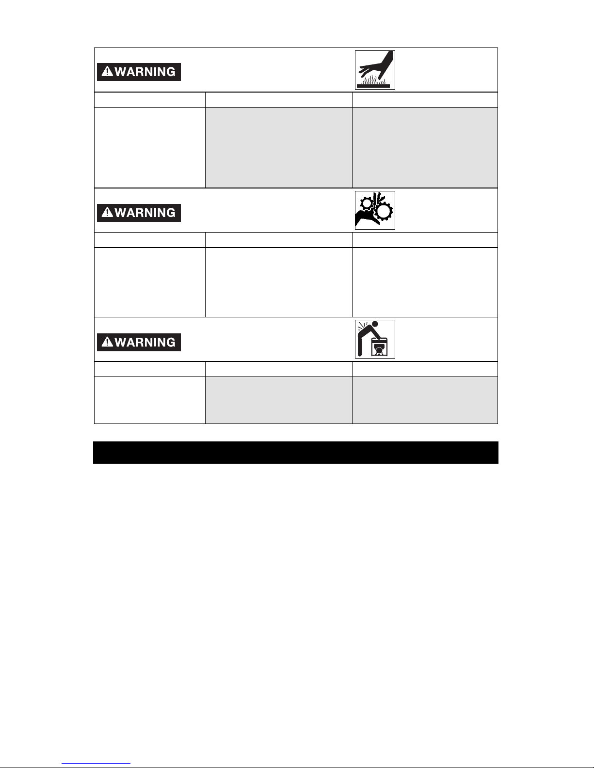
RISK OF HOT SURFACES
HAZARD WHA T CAN HAPPEN HOW TO PREVENT IT
Contact with hot
engine and generator
components.
Contact with hot surfaces, such
as en gines exhaust components,
could re sult in serious bur ns.
During operation, touch only
the con trol surfaces of the
generator. Keep chil dren away
from the gen er a tor at all times.
They may not be able to rec ognize the hazards of this
prod uct.
RISK OF MOVING P AR TS
HAZARD WHA T CAN HAPPEN HOW TO PREVENT IT
Contact with moving
parts can result in
serious injury.
The generator contains parts
which ro tate at high speed
during operation. These parts are
covered by guarding to prevent
injury .
Never operate generator
with guard ing or cover plates
removed. Avoid wearing loose
fitting clothing or jewelry and
contain long hair which could be
caught by moving parts.
RISK FROM LIFTING
HAZARD WHA T CAN HAPPEN HOW TO PREVENT IT
Lifting a very heavy
object.
Serious injury can result from
at tempt ing to lift too heavy an
object.
The generator is too heavy to
be lift ed by one person. Obtain
as sis tance from others before
you try to move it.
SPECIFICATIONS
MODEL BSV550-W
HORSE POWER 9.0
RATED/SURGE WATTS 5500/8850
VOLTAGE 120/240
AMPERAGE 45.8/22.9 A
PHASE SINGLE
FREQUENCY 60 Hz
ENGINE SPEED 3600 RPM
MAX. AMBIENT TEMP. 104° F
FUEL CAPACITY 7 GALLONS
RUN TIME @ 50%/100% 10.4/7.0 HRS
Note: Photographs and line drawings used in this manual are for reference only and
do not represent a specific model.
8- ENG
A16596
NOTE: Left and right describes the location of a part with the operator
facing the outlet panel.
UNPACKING
1. Open carton from top.
2. Cut carton along dotted lines.
3. Remove all carton inserts.
4. See portability Kit instructions to assemble the portability kit.
Read this manual. Do not at tempt to operate equipment
until you have read this Manual for Safety, Op er a tion, and
Maintenance In struc tions.
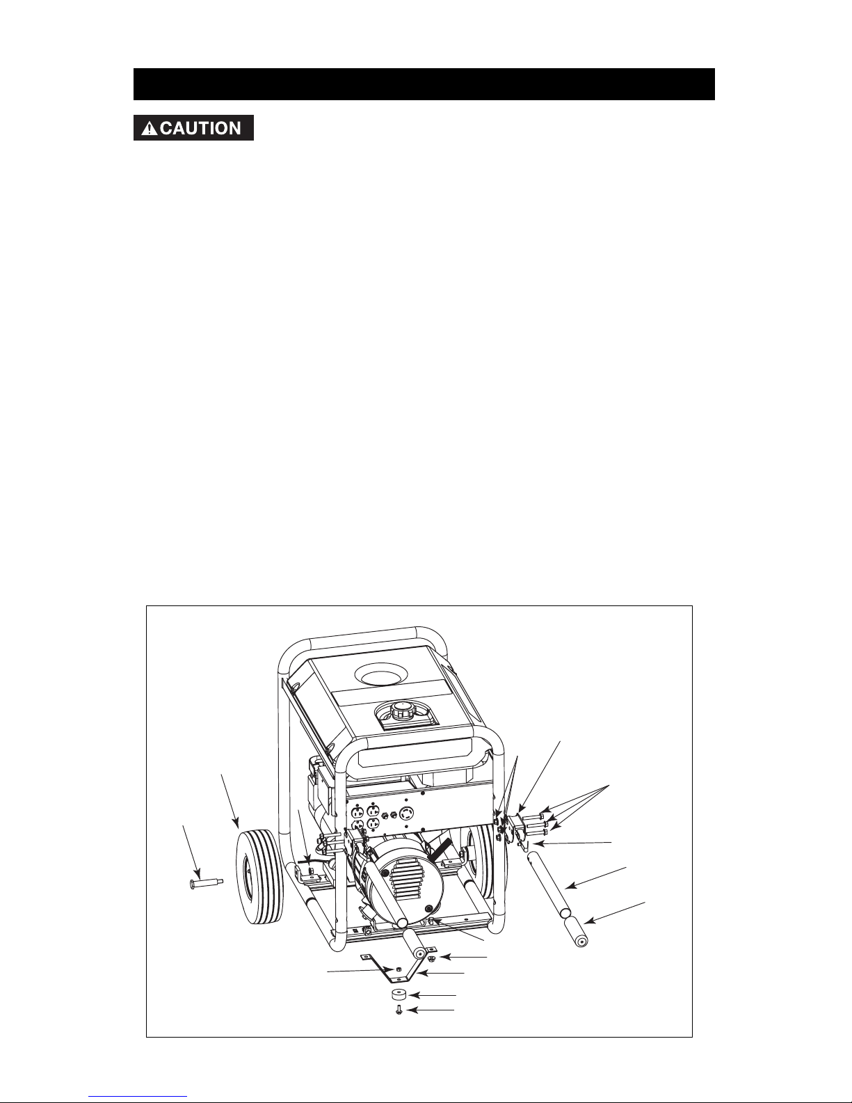
ASSEMBLE PORTABLILITY KIT
Tools needed:
1 - 1/2" socket
1 - 1/2" open end wrench
1 - 3/8" socket
1 - 3/8" open end wrench
1 - 7/8" socket
Kit Contains:
2 - Handles (1)
2 - Wheels (2)
1 - Foot Bracket (3)
1 - Rubber Bumper (4)
Parts bag contains:
2 - Handle Grips (5)
2 - Handle Brackets (6)
6 - Screws, 5/16-18 x 2.00 (7)
7 - Flange Nuts (8)
2 - Snap Buttons (9)
1 - Screw 5/16-18 x .75 (10)
2 - Bolt, 3/8-16 x 2.25 (11)
2 - Locknut, 3/8-16 (12)
1 - Screw 1/4-20 X .75 (13)
1 - Kep Nuts, 1/4-20 (14)
11
2
6
12
14
13
4
3
8
10
5
1
9
7
8
NOTE: The key numbers
in this figure are referenced
throughout the instructions.
ASSEMBLY
9 - ENG
A16596
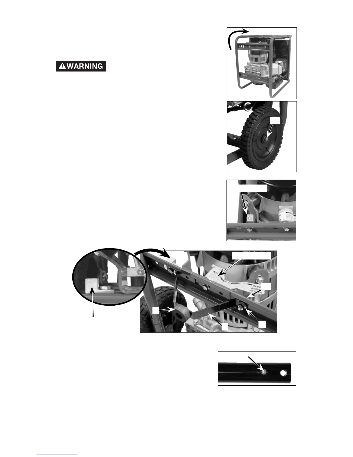
1. With the help of another person, tilt the generator
and rest on frame as shown. DO NOT remove
the shipping block until portability kit has been
assembled.
The generator is too heavy to
be lifted by one person. Obtain
assistance from others before lifting.
2. Assemble wheels to wheel brackets using shoulder
bolts (11) and locknuts (12).
3. Attach rubber bumper (4) to foot bracket (3) using
screw (13) and keps nut (14). Tighten securely.
4. Remove the ground lug. Save grounding lug, screw,
and flange nut to assemble foot bracket.
5. Attach foot bracket assembly (3) and ground lug to
generator frame as shown. Tighten screws securely.
NOTE: Make sure grounding lug is oriented as
shown.
6. To make installation easier, submerge handle grips into warm soapy water.
Remove handle grips from soapy water and slide
onto handles .
7. Squeeze snap button (9), slide into handle, and
release snap button through second hole. NOTE:
V of snap button is inserted first. Repeat step on
other handle.
8. Depress snap button (9), slide into handle bracket, and release through first
slot in handle bracket as shown. Secure handle to handle bracket with screw
(7) and flange nut (8).
9
11
grounding lug
shipping block
10
8
3
4
grounding lug
10- ENG
A16596
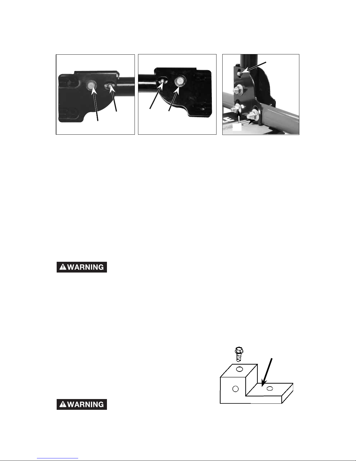
9. On other handle depress snap button (9), slide into handle bracket, and
release through first slot in handle bracket as shown. Secure handle to
handle bracket with screw (7) and flange nut (8).
10. Attach handle bracket assemblies to frame with screws (7) and flange nuts
(8). Tighten securely.
NOTE: Orientation of handle assemblies to frame will depend on how the
operator wishes to operate snap button (9). If snap button is assembled to
outside of the generator frame the fingers will operate it. If snap button is
assembled to inside of the generator frame the thumbs will operate it. The figure
shows the snap button assembled to inside of generator frame
11. Remove shipping block from under the gen head. Unscrew bolt and remove
the shipping block. It is very important that this is removed before starting
your generator.
12. Carefully tilt the generator to operating position.
13. The portability kit is now ready for use.
14. T o lower handle, depress snap button and fold handles down.
15. Raise handles and allow snap button to snap into place.
Risk of moving parts. Keep fingers away
from all moving parts. Contact with moving
parts can result in serious injury. Keep children away from
the generator at all times. They may not be able to recognize
the hazards of this product.
OTHER LOOSE PARTS
1. Oil is supplied, see engine operators manual for correct procedure to add oil
and fuel to engine.
IMPORTANT: Before any attempt to start your gen er a tor be sure to check engine
oil (See Engine Operator's man u al)
GROUNDING THE GENERA TOR
A grounding lug is supplied with the generator for
use when required by local electrical ordinances.
Refer to article 250 of the Na tion al Elec tri cal Code to
clarify any needed ground ing information. Your local
electric com pa ny or a certified electrician should be
able to help you with this in for ma tion.
Risk of fire. Do not use metal
pipe that is being used to carry
combustible materials or gases for the grounding point.
7
9
7
9
9
8
Grounding Lug
11 - ENG
A16596
EXTENSION CORDS
When using an appliance or tool at a considerable distance from the gen er a tor , a
3-wire extension cord that has a 3-blade grounding plug and a 3-slot receptacle
that accepts the tool's plug MUST be used in order to reduce the risk of electrical
shock. A cord of ad e quate size must be used. Using the fol low ing chart to de termine the min i mum wire size re quired.
*NOTE: When am per age exceeds 20 amp; a 12 gauge extension cord should
not be used for long dis tanc es.
An extension cord that is hot to the touch is over load ed.
Repair or replace damaged ex ten sion cords im me di ate ly.
DOUBLE THROW TRANSFER SWITCH
Potential hazards exist when a portable electric gen er a tor
is connected to the main electrical supply coming into the
house. It is at that point that the electrical generator could feed back into the
utility company's system causing pos si ble elec tro cu tion of workers who are
repairing the elec tri cal lines.
To avoid back feeding of electricity into utility systems, a double-throw transfer
switch must be installed between the generator and utility power. The DoubleThrow Transfer Switch should be installed by a licensed elec tri cian and in com pliance with all state and local electrical codes. (When in stall ing a Double-Throw
Transfer Switch, a minimum of 10 gauge wiring must be used.)
The electrician should also install a sub-panel to isolate the circuits you would
want to use during an emergency or elec tri cal power outage. Y our generator will
not be large enough to handle the load of all the lights, ap pli anc es, TV, etc. at one
time. To select which items to run during the electrical power outage, see Wattage
Cal cu la tion section in this manual.
OBT AINING ELECTRICITY FROM THE GENERATOR
There are ba si cal ly 2 ways to ob tain elec tric i ty from a gen er a tor:
1. Use of ex ten sion cords di rect ly from the generator to the appliance, lights,
tools, etc.
2. Use of a dou ble-throw transfer switch installed directly to the main elec tri cal
supply outside of house.
Extension Cord Wire Gauge Chart
Cord
Length
Wire Gauge
Size
Amperage
0 to 100 ft. 12 ga. *Up to 20 amp draw
0 to 100 ft. 10 ga. Up to 30 amp draw
12- ENG
A16596
OPERATION
KNOW YOUR GENERA TOR
Read this General Manual and Safety Rules be fore op er a tion of your
Generator. Compare the illustration in your parts manual with your gen er a tor to
familiarize your self with the lo ca tion of various controls and ad just ments. Save all
manuals for future references.
GENERA TOR CAPACITY
IMPORTANT: Exceeding the rated capacity of your gen er a tor can result in
serious damage to your gen er a tor and con nect ed elec tri cal devices. See the Watt-
age Cal cu la tion section in this manual to assist you in de ter min ing the appliances
and tools that can be run with the watt age capacity of your generator.
CIRCUIT BREAKERS
Each re cep ta cle has a circuit breaker to protect the gen er a tor from overloading.
If the cir cuit breaker trips, unplug all electrical loads from the gen er a tor . Let the
circuit break er cool down. Push circuit break er button to reset.
LOW OIL PROTECTION
Your generator engine is equipped with Low Oil Shutdown. Low Oil Shutdown is
a safety device designed to protect your engine from damage in the event the oil
level in the crankcase is low.
If while the engine is running, the oil gets low, it will automatically shut itself down
and will not restart until the oil is added. If the oil is low before start-up, the
generator will not start until oil is added.
NOTE: The Low Oil Shutdown mechanism is very sensitive. You must fill the
engine to the full mark on the dipstick to inactivate this safety device.
BEFORE START UP
This generator has been shipped from the factory with out oil in the
crankcase. Op er at ing the unit without oil can damage the engine.
Always check engine oil level before ev ery start. Running engine
low of oil or out of oil could result in serious damage to the engine.
Follow the steps listed below before starting generator:
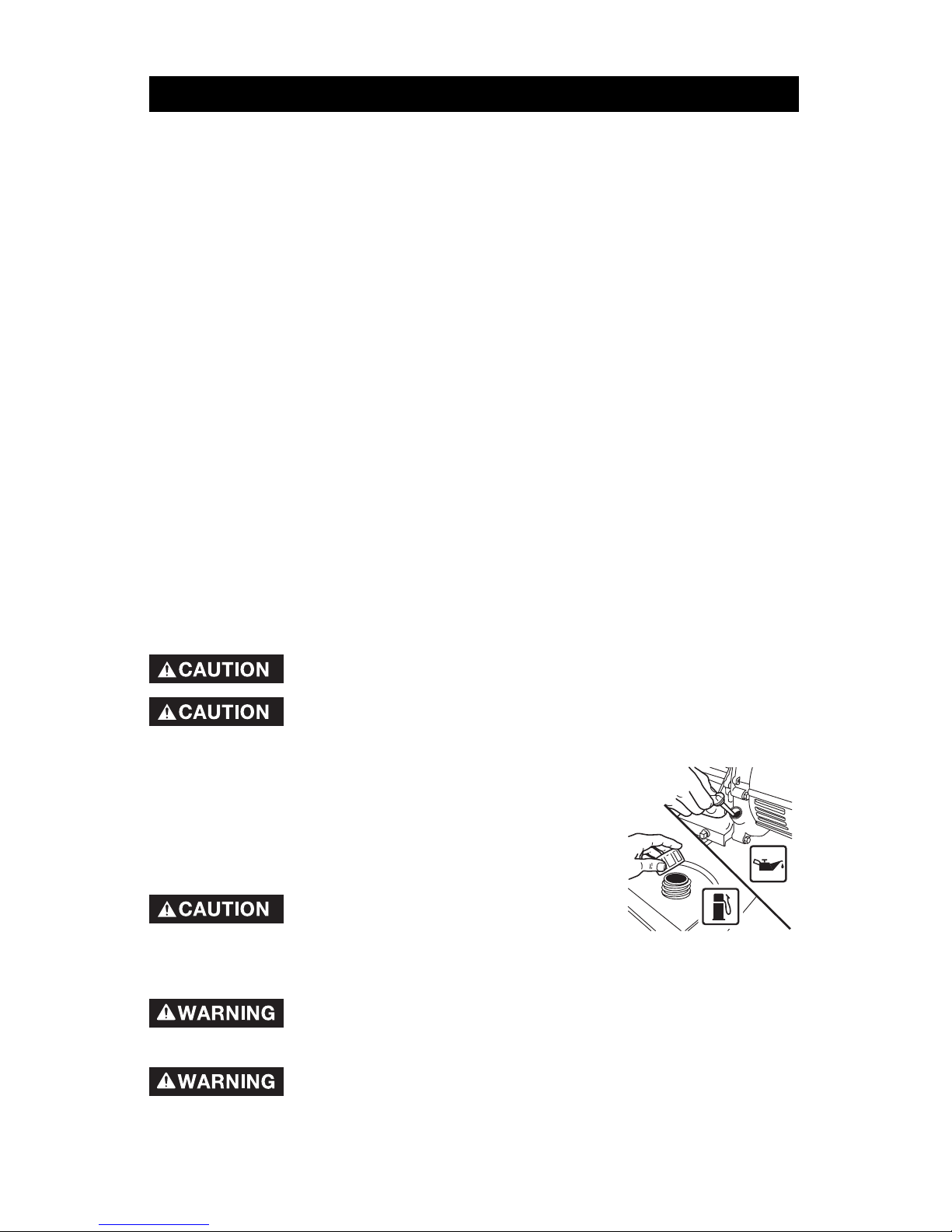
1. Check engine oil. Refer to the Engine Operator's
Manual for correct grade and quantity of oil.
2. Check fuel level, fill as required. Make sure gen er a tor
is turned off and has been allowed time to cool down.
Use clean, fresh, reg u lar unleaded gasoline with a
min i mum of 87 octane. Do not mix oil with gasoline.
Keep fuel out of the reach of children.
Never fill fuel tank completely. Fill tank
to 1/2" below the bottom of the filler neck to pro vide
space for fuel expansion. Wipe any fuel spillage from engine and equipment, and
make sure area is dry before starting engine.
Never fill fuel tank indoors. Fill generator in well ventilated area.
Never fill fuel tank when engine is running or hot. Do not smoke
when filling fuel tank. Never allow open flames or sparks in area.
Store fuel in an approved container. Store fuel in a well
ventilated area free of open flames or sparks.
13 - ENG
A16596
Never run engine indoors or in en closed, poor ven ti lat ed areas,
en gine exhaust contains carbon mon ox ide, an odorless and
deadly gas.
3. Make sure generator is grounded in accordance with local requirements.
4. All electrical loads MUST be disconnected.
Engine speed has been fac to ry set to pro vide safe op er a tion.
Tampering with the engine speed adjustment could re sult in
over heat ing of at tach ments and could cause a fire. Never attempt to "speed-up" the
TO ST ART THE ENGINE
Never run engine indoors or in en closed, poor ven ti lated areas, en gine ex haust contains car bon mon ox ide, an
odorless and deadly gas.
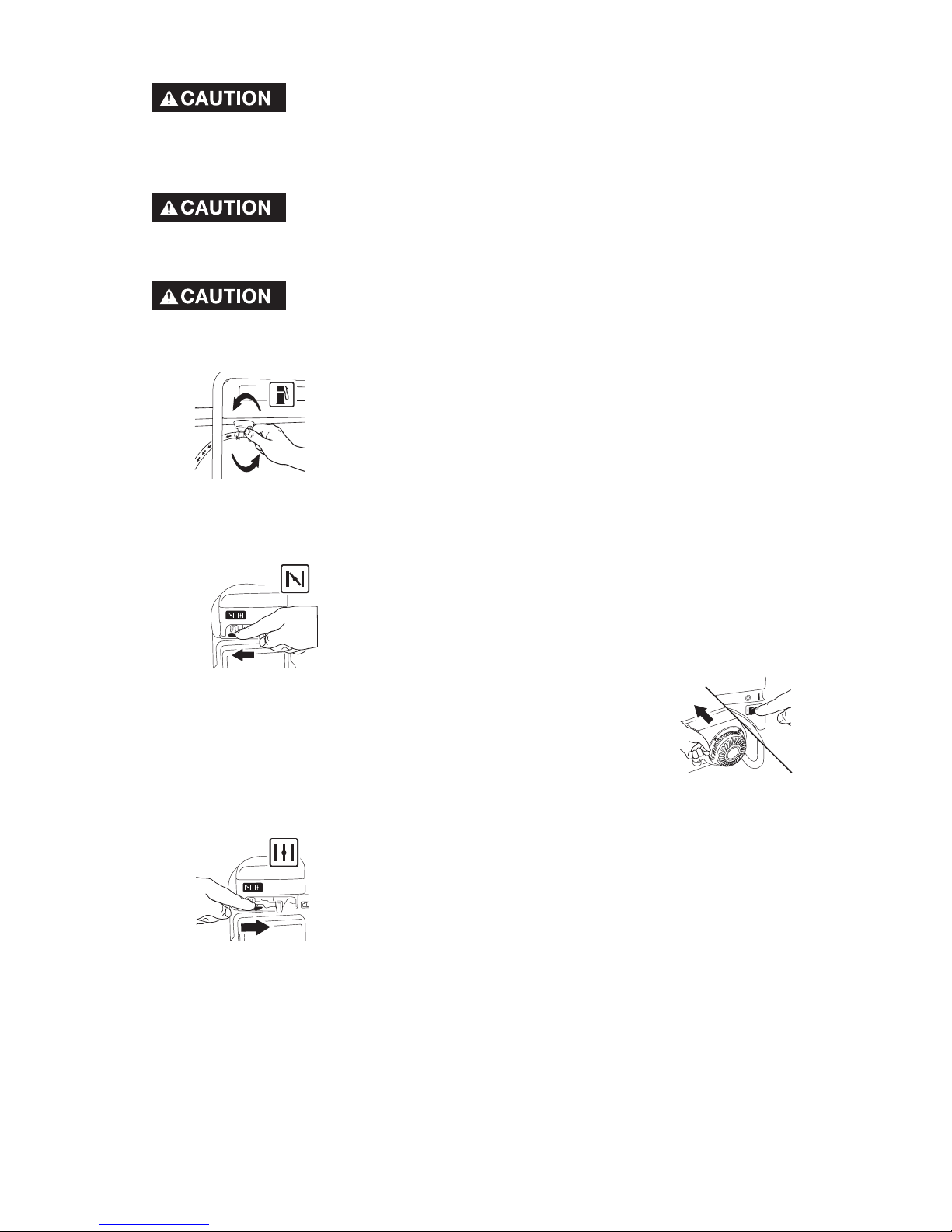
1. Open the fuel shut-off valve.
2. Move the choke control located on the engine to the "Choke" position.
NOTE: No choke is required on warm engines. make sure choke is in the "RUN"
position on warm engine starts.
3. On the engine there is a ON/OFF switch located on the front
panel of the engine. Place this switch to the "ON" position.
4. Grasp handle on rope starter and pull slowly until resistance
is felt. Let the rope rewind slowly. Pull rope with a rapid full
arm stroke. Let rope rewind slowly. Repeat if necessary.
5. When engine starts, gradually move the choke to the "RUN"
position.
IMPORTANT: Allow generator to run at no load for 5 minutes upon each initial
start-up to allow engine and generator to stabilize.

14- ENG
A16596
CONNECTING ELECTRICAL LOADS
1. Let engine run and warm up for five minutes after starting with no electrical
load.
Connect loads in the following manner to prevent damage to equipment:
2. Connect inductive load equipment first, inductive loads consist of
refrigerators, freezers, water pumps, air conditioners, or small hand tools.
Con nect the items that require the most watt age first. See Wattage Cal cu la-
tion Section in this man u al.
3. Connect the lights next.
4. Voltage sensitive equipment should be the last equipment connected to
the generator. Plug voltage sensitive appliances such at TV's, VCR's, mi crowaves, ovens, computers, and cordless telephones into a UL listed voltage
surge protector, then con nect the UL listed voltage surge protector to the
generator.
Failure to connect and operate equipment in this sequence
can cause damage to equipment and will void the warranty
on your generator.
Follow the wattage calculation table in the Wattage Calculation section of
this manual. Overloading the generator will cause power fluctuations and
can damage equipment and appliances.
Porter-Cable Corporation will only be responsible for damage to customer's
equipment when the generator is determined to be defective. This
determination will only be made by an authorized representative of PorterCable Corporation and this decision will be final. Porter-Cable Corporation
reserves the right to inspect the electrical connections at the customer's
site of operation and test the generator for proper operation before any
determination of liability is made. Failure to maintain the equipment or
wiring for inspection will void any claim for damages by the customer.
Porter-Cable Corporation will not be responsible for equipment damaged as
a result of voltage surges, improper operation or improper installation of the
generator.
STOPPING ENGINE
1. Disconnect all electrical loads.
2. Turn ON/OFF switch to "OFF" po si tion.
3. Close fuel shut-off valve.
15 - ENG
A16596
CUSTOMER RESPONSIBILITIES T ABLE
MAINTENANCE
GENERAL RECOMMENDA TIONS
The warranty of the generator does not cover items that have been subjected to
operator abuse or negligence. To receive full value from the warranty, operator
must main tain the generator as instructed in this manual.
ENGINE MAINTENANCE
Refer to the Engine Operator's manual for service and maintenance of the engine.
GENERA TOR MAINTENANCE
Your generator should be kept clean and dry at all times. The generator should
not be stored or operated in environments that includes ex ces sive moisture, dust
or any corrosive vapors. If these substances are on the gen er a tor, clean with
a cloth or soft bristle brush. Do not use a garden hose or anything with water
pressure to clean the gen er a tor. Water may enter the cooling air slots and could
pos si bly damage the rotor, stator and the internal wind ings of the generator head.
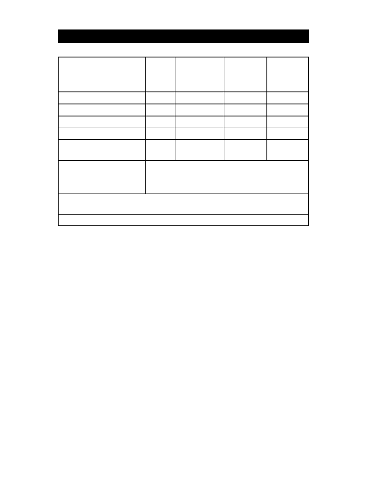
MAINTENANCE TASK
Before
each
use
Every 25
Hours
of Every
Season
Every 50
Hours
of Every
Season
Every 100
Hours
of Every
Season
Check oil level
X See Note 2
Change oil
See Note 1
Clean Air Filter Assembly
XX
Check Spark Plug
X
Check fuel line, hose
clamps and fuel tank
X
Prepare Unit for Storage
Prepare unit for storage if it is to remain idle
for more than 30 days.
Note 1: Change oil after first two (2) operating hours and every 50 operating
hours thereafter, more often if op er at ed in extreme dusty or dirty condition
Note 2: Check oil after 5 hours of operation.

16- ENG
A16596
If you are going to store your generator for more than 30 days, use the following
information as a guide to prepare the generator for storage.
Never store generator with fuel in the tank in doors or in
enclosed, poorly ven ti lat ed areas, where fumes can reach
an open flame, spark or pilot light as on a fur nace, water heater, clothes
dryer or other gas ap pli anc es.
ENGINE PREPARATION
1. Add fuel stabilizer to fuel tank to minimize the formation of fuel gum deposits
during stor age.
2. Run engine at least 10 minutes after adding sta bi liz er to allow it to enter the
fuel system.
3. Next shut off engine.
4. Disconnect the spark plug wire and remove the spark plug.
5. Add one teaspoon of oil through the spark plug hole.
6. Place rag over spark plug hole and pull the recoil a few times to lubricate the
combustion cham ber.
7. Replace the spark plug, but do not connect the spark plug wire.
NOTE: If a fuel stabilizer is not used, all gasoline must be drained from the tank
and carburetor to prevent gum deposits from forming on these parts and causing
possible malfunction of the engine.
GENERA TOR
• Clean the generator as outlined in the Maintenance Section on this manual.
• Check that cooling air slots and openings on gen er a tor are open and
unobstructed.
• Make sure that the generator storage area is free of excessive humidity and
dust.
• Store the generator in dry, well ventilated areas.”
STORAGE

17 - ENG
A16596
WATTAGE CALCULATIONS
Never exceed the rated capacity of your generator. Se ri ous damage to the
generator or appliance could result from an overload.
1. Starting and running wattage requirements should always be calculated
when matching a generators wattage capacity to the appliance or tool.
2. There are two types of electrical appliances that can be powered by your
generator:
A. Items such as ra di os, light bulbs, television sets, and microwaves have
a "re sis tive load". Starting wattage and running wattage are the same.
B. Items such as re frig er a tors, air com pres sors, washer, dryer, and hand
tools that use an elec tri cal motor have an "inductive load". Inductive
load appliances and tools require ap prox i mate ly 2 to 4 times the listed watt age for starting the equip ment. This ini tial load only lasts for a
few sec onds on start-up but is very im por tant when figuring your total
wattage to be used.
C. Al ways start your largest electric motor first, and then plug in other
items, one at a time.
NOTE: On 120-volt loads the maximum starting wattage should NOT exceed
one half of the rated gen er a tor wattage. Example: a 5000 rated wattage
generator = 2500 maximum starting wattage.
IMPORTANT
DETERMINING WATTAGE REQUIREMENTS
Before operating this generator list all of the appliances and/or tools that are going
to operate at the same time. (Then determine the starting wattage requirements
and the running wattage requirements by following example and/or refer to
household wattage calculator.)
1. First total the running wattage of all appliances and/or tools that will be
operated at the same time.
Running Watts Starting Watts
Example 1:
Lights = 100 Watts 0
Television = 300 Watts 0
Slow Cooker = 250 Watts 0
TOTAL =650 Watts 0
2. Next the starting wattages of any appliances and/or tools that will start and
stop during operation.
Running Watts Starting Watts
Example 2:
Small Refrigerator 500 Watts 2000 Watts
TOTAL =500 Watts 2000 Watts
3. The running wattage of examples 1 & 2 totals 1150 watts. The starting
wattage of the small refrigerator is 2000 watts which is 1500 watts more
than the running watts. Take this difference of 1500 starting watts from the
refrigerator and add to the total running watts of 1150.
Example 3: 1500 Starting Watts
1150 Running Watts
TOTAL =2650 Total Watts
Generator must have a maximum capacity of at least 2650 watts.
18- ENG
A16596
STARTING WATTAGE REQUIREMENTS
1. Some appliances and tools will list on the motor nameplate the starting and
running voltage and amperage requirements. Use the following formula to
con vert voltage and am per age to watt age:
Volts X Amp = Watts
Example: 120 volts x 10 amps = 1200 watts
2. To determine the approximate starting wattage re quirement for most
appliances and tools with inductive type motors, multiply the wattage that
was calculated by 2 to 4 times to assure adequate generator capacity. If the
nameplate information is not avail able use the values on the following chart
as a guide.
3. Remember that the starting and running wattage for resistive loads are the
same. (Example: a 100 watt light bulb requires only 100 watts to start.) Most
resistive loads will be listed in wattage.
The wattage ratings shown are averages. Wattage requirements may vary
with different brands of appliances. Use wattage values specified on
appliance nameplate.
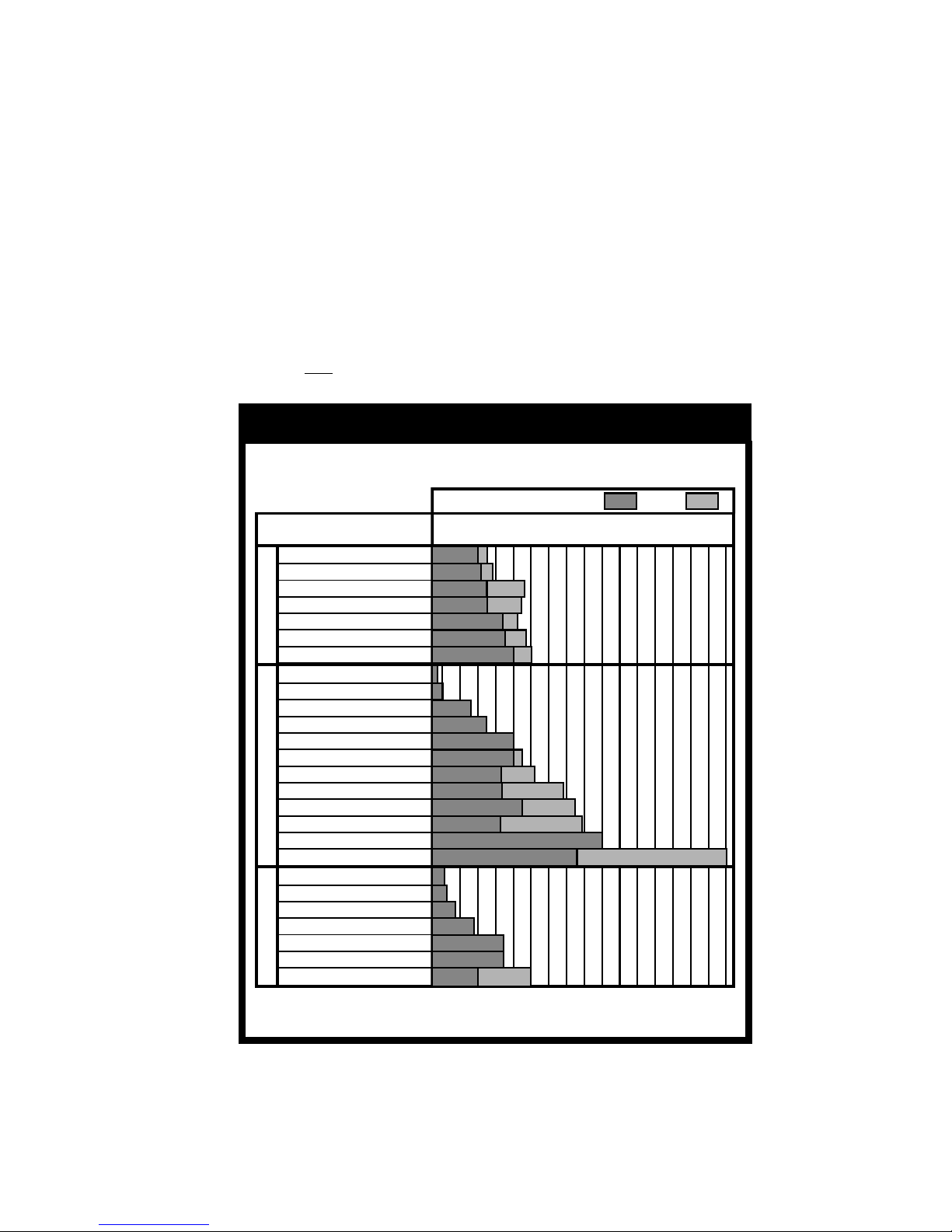
Application Guide
To select the right generator for your needs, total the wattage
of the items to be run at the same time.
Run
Electric Appliance
Wattage
ContractorEmergency ReliefRecreational
3/8" Hand Drill
Jigsaw
1/3 HP Airless Sprayer
6" Bench Grinder
Belt Sander
Demolition Hammer
7 1/4" Circular Saw
Light Bulb
Home Security
Television
Microwave
Toaster Oven
Portable Heater (5,000 BTU)
Furnace Fan
Refrigerator/Freezer
Sump Pump
Clothes Washer
Water Heater
Air Conditioner (20,000 BTU)
12V DC Battery Charger
Radio
Slow Cooker
Electric Blanket
Electric Skillet
Coffee Maker
Small Refrigerator
100
250
500
1000
1500
2000
2500
3000
3500
4000
4500
5000
5500
6000
6500
7000
7500
Start
19 - ENG
A16596
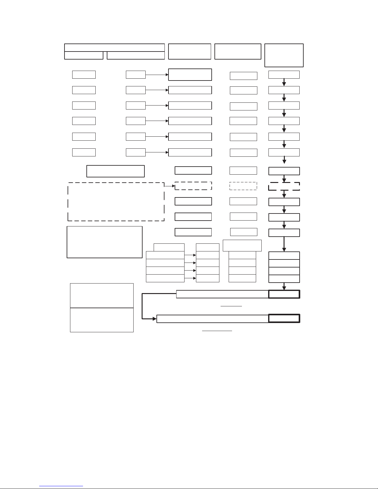
APPLIANCE OR
LOAD DEVICE*
REFRIGERATOR/
FREEZER
800
SMALL REFRIGERATOR
AIR COND.(ROOM)
SUMP PUMP 1/2 HP
600
TELEVISION
CAUTION !!
HOT PLATE
MICROWAVE
SPACE HEATER
2400
1000
3
2
LIGHTING
60 WATT BULBS
75 WATT BULBS
100 WATT BULBS
300 WATT BULBS
ELECTRIC LOAD GRAND TOTAL
THIS TOTAL MUST BE LESS THAN YOUR GENERATOR RATING
WATTAGE RATING OF YOUR GENERATOR
TOTAL
THIS TOTAL MUST BE GREATER THAN YOUR HOUSEHOLD WATTAGE LOAD
TYPICAL DEVICE
WATTAGE**
2400
1800
7200
2000
300
1500
800
1500
WATER HEATER
4000
TIMES NUMBER
OF BULBS
60
75
100
300
CAUTION !!
WATTS
DEVICES WITH HIGH STARTING (INDUCTIVE)LOADS
RUN WATTS
TIMES (X) START FACTOR
DO NOT CONNECT VOLTAGE SENSITIVE
ELECTRONIC EQUIPMENT (TV SET, COMPUTER,
ETC.) DIRECTLY TO YOUR GENERATOR. IF YOU USE
THE GENERATOR TO POWER SENSITIVE EQUIPMENT
YOU MUST USE A U.L. LISTED VOLTAGE SURGE
PROTECTOR.
NOTICE: FAILURE TO USE A U.L. LISTED VOLTAGE
SURGE PROTECTOR WILL DAMAGE YOUR
EQUIPMENT AND VOID YOUR WARRANTY.
3
3
THE IDLE CONTROL MUST BE IN THE
OFF POSITION WHEN OPERATING
LARGE MOTOR LOADS (FREEZERS,
REFRIGERATORS,ETC.) OR VOLTAGE
SENSITIVE ELECTRONIC EQUIPMENT
(TV, COMPUTERS, ETC.)
FURNACE FAN 1/3 HP
800 3
2400
WELL PUMP 1/2 HP
1000 2
2000
*FOR PRODUCTS NOT
LISTED REFER TO
CALCULATION
INSTRUCTIONS
**AVERAGE VALUES -
ACTUAL INDIVIDUAL
DEVICE VOLTAGES MAY
BE HIGHER OR LOWER
x
x
x
x
=
=
=
=
=
=
=
=
=
=
=
=
=
=
=
x
x
x
x
x
x
=
=
=
=
=
=
=
=
=
=
=
HOUSEHOLD WATTAGE CALCULATOR

20- ENG
A16596
TROUBLESHOOTING GUIDE
PROBLEM CAUSE CORRECTION
Engine will
not start
1. Low on fuel or oil. 1. Add fuel or oil.
2. Ignition switch in "Off"
position.
2. Turn to "ON" position
3. Faulty spark plug. 3. Replace spark plug.
4. Choke in wrong position. 4. Adjust choke accordingly.
5. Fuel shut-off valve in
closed position
5. Open fuel shut-off valve.
6. Unit loaded during start-up. 6. Remove load from unit.
7. Spark plug wire loose.
7. Attach wire to spark plug.
No electrical
output
1. Faulty receptacle. 1. Have Service Center
replace.
2. Circuit breaker kicked out. 2. Depress and reset.
3. Defective capacitor. 3. Have Service Center
replace capacitor.
4. Faulty power cord. 4. Repair or replace cord.
5. GFCI switch br eaker kicked
out (if equipped)
5. Depress and reset
Repeated
circuit
breaker
tripping
1. Overload 1. Reduce load.
2. Faulty cords or equipment 2. Check for damaged,
bare, or frayed wires on
equipment. Replace.
Generator
overheating
1. Generator overloaded. 1. Reduce load.
2. Insufficient ventilation. 2. Move to adequate supply
of fresh air.

21 - ENG
A16596
A complete line of accessories is available from your Porter -Cable•Delta Supplier, Porter-
Cable•Delta Factory Service Centers, and Porter -Cable Authorized Service Stations. Please
visit our Web Site www.porter-cable. com for a catalog or for the name of your nearest
supplier.
Since accessories other than those offered by Porter-Cable•Delta
have not been tested with this product, use of such accessories
could be hazardous. For safest operation, only Porter -Cable•Delta recommended
accessories should be used with this product.
ACCESSORIES
SERVICE
REPLACEMENT PARTS
When servicing use only identical replacement parts. For a service parts list or to
learn more about Porter-Cable visit our website at www.porter-cable.com.
SERVICE AND REPAIRS
All quality tools will eventually require servicing, or replacement of parts due
to wear from normal use. For assistance with your tool, visit our website at
www.porter-cable.com for a list of service centers or call the Customer Care
Department at 1-888-848-5175. All repairs made by our service centers are fully
guaranteed against defective material and workmanship. We cannot guarantee
repairs made or attempted by others.
Should you have any questions about your tool, feel free to write us at any time. In
any communications, please give all information shown on the nameplate of your
tool (model number, type, serial number , etc.).

22- ENG
A16596
LIMITED WARRANTY
PORTER-CABLE warrants to the original purchaser that all products covered under this warranty are free from
defects in material and workmanship. Products covered under this warranty include air compressors, air tools,
service parts, pressure washers, and generators, which have the following warranty periods:
3 YEARS - Limited warranty on 2-stage oil-free air compressor pumps that operate at 1725 RPM.
2 YEARS - Limited warranty on oil-lubricated air compressor pumps.
1 YEAR - Limited warranty on all other air compressor components.
2 YEARS - Limited warranty on electric generator alternators.
1 YEAR - Limited warranty on other generator components.
2 YEARS - Limited warranty on pneumatic air tools as described in Porter-Cable general catalog.
1 YEAR - Limited warranty on pressure washers used in consumer applications (i.e. personal residential
household usage only).
90 DAY - Pressure washers used for commercial applications (income producing) and service parts.
1 YEAR - Limited warranty on all accessories.
Porter-Cable will repair or replace, at Porter-Cable's option, products or components which have failed within
the warranty period. Service will be scheduled according to the normal work flow and business hours at the
service center location, and the availability of replacement parts. All decisions of Porter-Cable with regard to
this limited warranty shall be final.
This warranty gives you specific legal rights, and you may also have other rights which vary from state to state.
RESPONSIBILITY OF ORIGINAL PURCHASER (initial User):
• To process a warranty claim on this product, DO NOT return it to the retailer. The product must be evalu-
ated by a Porter-Cable Authorized Warranty Service Center. For the location of the nearest Porter-Cable
Authorized Warranty Service Center call 1-888-848-5175, 24 hours a day, 7 days a week.
• Retain original cash register sales receipt as proof of purchase for warranty work.
• Use reasonable care in the operation and maintenance of the product as described in the Owners
Manual(s).
• Deliver or ship the product to the nearest Porter-Cable Authorized Warranty Service Center. Freight costs,
if any, must be paid by the purchaser.
• Air compressors with 60 and 80 gallon tanks will be inspected at the site of installation. Contact the nearest
Porter-Cable Authorized Warranty Service Center that provides on-site service calls, for service call ar-
rangements.
• If the purchaser does not receive satisfactory results from the Porter-Cable Authorized Warranty Service
Center, the purchaser should contact Porter-Cable.
THIS WARRANTY DOES NOT COVER:
• Merchandise sold as reconditioned, used as rental equipment, and floor or display models.
• Merchandise that has become damaged or inoperative because of ordinary wear, misuse*, cold, heat, rain,
excessive humidity, freeze damage, use of improper chemicals, negligence, accident, failure to operate the
product in accordance with the instructions provided in the Owners Manual(s) supplied with the product,
improper maintenance, the use of accessories or attachments not recommended by Porter-Cable, or
unauthorized repair or alterations.
* An air compressor that pumps air more than the recommended duty cycle during a one hour period may
be considered misuse.
• Repair and transportation costs of merchandise determined not to be defective.
• Costs associated with assembly, required oil, adjustments or other installation and start-up costs.
• Expendable parts or accessories supplied with the product which are expected to become inoperative or
unuseable after a reasonable period of use, including but not limited to sanding disks or pads, saw and
shear blades, grinding stones, springs, chisels, nozzles, o-rings, air jets, washers and similar accessories.
• Merchandise sold by Porter-Cable which has been manufactured by and identified as the product of
another company, such as gasoline engines. The product manufacturer's warranty, if any, will apply.
• ANY INCIDENTAL, INDIRECT OR CONSEQUENTIAL LOSS, DAMAGE, OR EXPENSE THAT MAY
RESULT FROM ANY DEFECT, FAILURE OR MALFUNCTION OF THE PRODUCT IS NOT COVERED BY
THIS WARRANTY. Some states do not allow the exclusion or limitation of incidental or consequential dam-
ages, so the above limitation or exclusion may not apply to you.
• IMPLIED WARRANTIES, INCLUDING THOSE OF MERCHANTABILITY OR FITNESS FOR A PARTICU-
LAR PURPOSE, ARE LIMITED TO ONE YEAR FROM THE DATE OF ORIGINAL PURCHASE. Some
states do not allow limitations on how long an implied warranty lasts, so the above limitations may not
apply to you.
®
Porter-Cable
Jackson, TN USA
1-888-848-5175
 Loading...