

Page 1

Laminate TrimmerInstruction
manual
The Model and Serial No. plate is located on the main
housing of the tool. Record these numbers in the
spaces below and retain for future reference.
Model No. ______________________________________
Type ___________________________________________
Serial No. _______________________________________
IMPORTANT
Please make certain that the person who is
to use this equipment carefully reads and
understands these instructions before
starting operations.
Part No. 903547 - 06-23-03
ESPAÑOL: PÁGINA 15
FRANÇAISE : PAGE 29
To learn more about Porter-Cable
visit our website at:
http://www.porter-cable.com
MODEL
310
Copyright © 2003 Porter-Cable Corporation
Page 2

2
Some dust created by power sanding, sawing, grinding,
drilling, and other construction activities contains chemicals known (to the
State of California) to cause cancer, birth defects or other reproductive harm.
Some example of these chemicals are:
●●
lead from lead-based paints
●●
crystalline silica from bricks and cement and other masonry products
●●
arsenic and chromium from chemically-treated lumber
Your risk from these exposures varies, depending on how often you do this
type of work. To reduce your exposure to these chemicals: work in a well
ventilated area, and work with approved safety equipment, always wear
MSHA/NIOSH approved, properly fitting face mask or respirator when using such tools.
SAFETY GUIDELINES - DEFINITIONS
indicates an imminently hazardous situation which, if not
avoided, will result in death or serious injury.
indicates a potentially hazardous situation which, if not
avoided,could result in death or serious injury.
indicates a potentially hazardous situation which, if not
avoided,may result in minor or moderate injury.
used without the safety alert symbol indicates potentially
hazardous situation which, if not avoided, may result in
property damage.
This manual contains information that is important for you to know and understand. This information relates to protecting YOUR SAFETY and PREVENTING
EQUIPMENT PROBLEMS. To help you recognize this information, we use the
symbols below. Please read the manual and pay attention to these sections.
Page 3
3
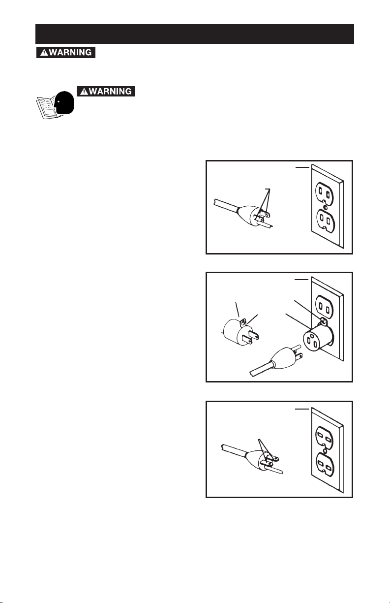
GROUNDING INSTRUCTIONS
This tool should be grounded while in
use to protect the operator from electric
shock. The tool is equipped with a 3conductor cord and 3-prong grounding
type plug to fit the proper grounding
type receptacle. The green (or green
and yellow) conductor in the cord is the
grounding wire. Never connect the
green (or green and yellow) wire to a live
terminal.
If your unit is for use on less than 150 V,
it has a plug that looks like that shown
in Figure (A).
If it is for use on 150 to 250 V, it has a
plug that looks like that shown in Figure
(C).
An adapter, see Figure (B) is available
for connecting Figure (B) type plugs to
2-prong receptacles. The greencolored rigid ear, lug, or the like,
extending from the adapter must be
connected to a permanent ground,
such as a properly grounded outlet box.
No adapter is available for a plug as
shown in Figure (C).
EXTENSION CORDS
Use only 3-wire extension cords that
have 3-prong grounding-type plugs
and 3-pole receptacles that accept the
tool’s plug. Replace or repair damaged
cords.
GROUNDED OUTLET BOX
Fig. A
Fig. B
Fig. C
CURRENT
CARRYING
PRONGS
GROUNDING PRONG
IS LONGEST OF THE 3 PRONGS
GROUNDED OUTLET BOX
GROUNDED OUTLET BOX
GROUNDING MEANS
ADAPTER
CURRENT
CARRYING
PRONGS
GROUNDING PRONG
IS LONGEST OF THE 3 PRONGS
Read and understand all instructions. Failure to
follow all instructions listed below, may result in electric shock, fire
and/or serious personal injury.
SAVE THESE INSTRUCTIONS.
IMPORTANT SAFETY INSTRUCTIONS
When using electric tools, basic safety precautions should
always be followed to reduce the risk of fire, electric shock, and personal
injury, including the following:
Read All Instructions.
Page 4

4
1. Keep Work Area Clean. Cluttered areas and benches invite injuries.
2. Consider Work Area Environment. Don’t expose power tools to rain.
Don’t use power tools in damp or wet locations. Keep work area well lit. Do
not use tool in presence of flammable liquids or gases.
3. Guard Against Electric Shock. Prevent body contact with grounded
surfaces. For example; pipes, radiators, ranges, refrigerator enclosures.
4. Keep Children Away. Do not let visitors contact tool or extension cord. All
visitors should be kept away from work area.
5. Store Idle Tools. When not in use, tools should be stored in dry, and high
or locked-up place – out of reach of children.
6. Don’t Force Tool. It will do the job better and safer at the rate for which it
was intended.
7. Use Right Tool. Don’t force small tool or attachment to do the job of a
heavy-duty tool. Don’t use tool for purpose not intended – for example –
don’t use circular saw for cutting tree limbs or logs.
8. Dress Properly. Do not wear loose clothing or jewelry. They can be
caught in moving parts. Rubber gloves and non-skid footwear are
recommended when working outdoors. Wear protective hair covering to
contain long hair.
9. Use Safety Glasses. Also use face or dust mask if cutting operation is
dusty.
10. Don’t Abuse Cord. Never carry tool by cord or yank it to disconnect
from receptacle. Keep cord from heat, oil, and sharp edges.
11. Secure Work. Use clamps or a vise to hold work. It’s safer than using
your hand and it frees both hands to operate tool.
12. Don’t Overreach. Keep proper footing and balance at all times.
13. Maintain Tools With Care. Keep tools sharp and clean for better and
safer performance. Follow instructions for lubricating and changing
accessories. Inspect tool cords periodically and if damaged, have repaired
by authorized service facility. Inspect extension cords periodically and
replace if damaged. Keep handles dry, clean, and free from oil and grease.
14. Disconnect Tools. When not in use, before servicing, and when
changing accessories, such as blades, bits, cutters.
15. Remove Adjusting Keys and Wrenches. Form habit of checking to see
that keys and adjusting wrenches are removed from tool before turning it on.
16. Avoid Unintentional Starting. Don’t carry tool with finger on switch. Be
sure switch is off when plugging in.
17. Extension Cords. Make sure your extension cord is in good condition.
When using an extension cord, be sure to use one heavy enough to carry the
current your product will draw. An undersized cord will cause a drop in line
voltage resulting in loss of power and overheating. The EXTENSION CORD
SELECTION table shows the correct size to use depending on cord length
and nameplate ampere rating. If in doubt, use the next heavier gage. The
smaller the gage number, the heavier the cord.
18. Outdoor Use Extension Cords. When tool is used outdoors, use only
extension cords intended for use outdoors and so marked.
Page 5

5
19. Stay Alert. Watch what you are doing. Use common sense. Do not
operate tool when you are tired.
20. Check Damaged Parts. Before further use of the tool, a guard or other
part that is damaged should be carefully checked to determine that it will
operate properly and perform its intended function. Check for alignment of
moving parts, binding of moving parts, breakage of parts, mounting, and any
other conditions that may affect its operation. A guard or other part that is
damaged should be properly repaired or replaced by an authorized service
center unless otherwise indicated elsewhere in this instruction manual. Have
defective switches replaced by authorized service center. Do not use tool if
switch does not turn it on and off.
SAVE THESE INSTRUCTIONS
1. Hold tool by insulated gripping surfaces when performing an
operation where the cutting tools may contact hidden wiring or its own
cord. Contact with a “live” wire will make exposed metal parts of the tool
“live” and shock the operator.
2. Use recommended accessories only. The use of improper accessories
may cause risk of personal injury.
3. Use certified safety equipment. Eye protection equipment should
comply with ANSI Z87.1 standards, hearing equipment should comply with
ANSI S3.19 standards, and dust mask protection should comply with
MSHA/NIOSH certified respirator standards.
4. Never adjust depth of cut while motor is running. A slip at this time
may cause personal injury, or damage to cutter or workpiece.
5. Be sure cord set is free and will not “hang up” during trimming
operations.
6. Keep hands clear of cutter when motor is running to prevent
personal injury.
7. Maintain firm grip on trimmer when starting motor to resist starting
torque.
8. Stay alert and keep cutter clear of all foreign objects while motor is
running.
9. Be sure motor has completely stopped before setting machine
down between operations.
10. Never touch bit immediately after use, as it may be extremely hot.
11. Do not use Laminate Trimmer motor without the Laminate Trimmer
Base installed. Loss of control could result, causing personal injury, or
damage to work.
12. Some wood contains preservatives which can be toxic. Take extra
care to prevent inhalation and skin contact when working with these
materials. Request, and follow, any safety information available from your
material supplier.
ADDITIONAL SPECIFIC SAFETY RULES
Technical Service Manager
Porter-Cable Corporation
4825 Highway 45 North
Jackson, TN 38305
There are certain applications for which this tool was
designed. Porter-Cable strongly recommends that this tool NOT be modified
and/or used for any application other than for which it was designed. If you have
any questions relative to its application DO NOT use the tool until you have
written Porter-Cable and we have advised you.
Page 6

6
SYMBOL DEFINITION
V ........................ volts
A ........................ amperes
Hz ........................ hertz
W ........................ watts
kW ........................ kilowatts
µF ........................ microfarads
l ........................ liters
kg ........................ kilograms
N/cm
2
........................ newtons per square centimeter
Pa ........................ pascals
h ........................ hours
min ........................ minutes
s ........................ seconds
........................ alternating current
3 ........................ three-phase alternating current
3
N ........................ three-phase alternating current with neutral
........................ direct current
n
0
........................ no load
........................ alternating or direct current
....................... Class II Construction
........................ splash-proof construction
........................ watertight construction
…/min ........................ revolutions or reciprocation per minute
REPLACEMENT PARTS
When servicing use only identical replacement parts.
MOTOR
Many Porter-Cable tools will operate on either D.C., or single phase 25 to 60
cycle A.C. current and voltage within plus or minus 5 percent of that shown
on the specification plate on the tool. Several models, however, are designed
for A.C. current only. Refer to the specification plate on your tool for proper
voltage and current rating.
Do not operate your tool on a current on which the
voltage is not within correct limits. Do not operate tools rated A.C.
only on D.C. current. To do so may seriously damage the tool.
EXTENSION CORD SELECTION
If an extension cord is used, make sure the conductor size is large enough to
prevent excessive voltage drop which will cause loss of power and possible
motor damage. A table of recommended extension cord sizes will be found
in this section. This table is based on limiting line voltage drop to 5 volts (10
volts for 230 volts) at 150% of rated amperes.
If an extension cord is to be used outdoors it must be marked with the suffix
W-A or W following the cord type designation. For example – SJTW-A to
indicate it is acceptable for outdoor use.
SYMBOLS
Page 7

7
RECOMMENDED EXTENSION CORD SIZES FOR USE WITH PORTABLE ELECTRIC TOOLS
FOREWORD
The Porter-Cable Model 310 Laminate Trimmer is designed for trimming
laminated plastics, phenolics and other similar materials having a bonding
agent too hard to be trimmed with ordinary tools.
SELECTING THE BIT
The Model 310 is equipped with a
1
/4" diameter collet to accept laminate
trimming bits with
1
/4" diameter shanks.
A – Motor Unit G – Ring Spring
B – Base Unit H – Clamp Knob
C – Sub-Base J – Collet Nut
F – Depth Adjusting Ring K – Switch
A
F
G
H
C
B
K
J
H
C
Fig. 1
Length of Cord in Feet
115V 25 Ft. 50 Ft. 100 Ft. 150 Ft. 200 Ft. 250 Ft. 300 Ft. 400 Ft. 500 Ft.
230V 50 Ft. 100 Ft. 200 Ft. 300 Ft. 400 Ft. 500 Ft. 600 Ft. 800 Ft. 1000 Ft.
0-2 18 18 18 16 16 14 14 12 12
2-3 18 18 16 14 14 12 12 10 10
3-4 18 18 16 14 12 12 10 10 8
4-5 18 18 14 12 12 10 10 8 8
5-6 18 16 14 12 10 10 8 8 6
6-8 18 16 12 10 10 8 6 6 6
8-10 18 14 12 10 8 8 6 6 4
10-12 16 14 10 8 8 6 6 4 4
12-14 16 12 10 8 6 6 6 4 2
14-16 16 12 10 8 6 6 4 4 2
16-18 14 12 8 8 6 4 4 2 2
18-20 14 12 8 6 6 4 4 2 2
Nameplate Ampere Rating
FUNCTIONAL DESCRIPTION
ASSEMBLY
Page 8

8
TO INSTALL BIT
1. DISCONNECT TOOL FROM POWER SOURCE.
2. Remove power unit from base unit as follows:
a. Loosen clamping knob (H) Fig. 1.
b. Grasp power unit (A) Fig. 1, and pull straight up and out of the base
unit (B) Fig. 1. This will also release the depth adjusting ring (F) Fig. 1,
from ring springs (G) Fig. 1.
3. Lay power unit on bench with collet toward you.
4. Clean and insert shank of bit into collet until end of shank bottoms. Then
pull out approximately
1
/16".
5. Place one wrench on flats of shaft directly above collet nut (J) Fig. 1. Let
far end of wrench rest on bench to your RIGHT.
6. Place other wrench on collet nut (J) Fig. 1, and turn clockwise to tighten.
TIGHTEN SECURELY.
TO REMOVE THE BIT
NEVER TOUCH BIT IMMEDIATELY AFTER USE, AS IT
MAY BE EXTREMELY HOT.
1. Repeat Steps 1 through 3 under TO INSTALL BIT.
2. Place one wrench on flats of shaft directly above collet nut (J) Fig. 1. Let
far end of wrench rest on bench to your LEFT.
3. Place other wrench on collet nut and turn counterclockwise and loosen
only enough to allow removal of bit. NEVER TIGHTEN COLLET NUT
WITHOUT BIT IN COLLET. This may allow collet to deform and weaken
clamping ability.
ADJUSTING BIT EXPOSURE
1. DISCONNECT TOOL FROM POWER SOURCE.
2. With power unit removed from base unit, turn depth adjusting ring to
position ring approximately six threads from top of power unit.
3. Insert power unit into base unit, aligning one of the grooves in the motor
housing with the pin protruding from inner wall of the base. Proceed until ring
springs snap into groove in depth adjusting ring.
4. Viewing power unit from top, turn depth adjusting ring clockwise to
decrease depth of cut, or counterclockwise to increase depth of cut.
NOTE: For convenience in making slight adjustments, a marker can be found
on the base next to the ring spring. The depth adjusting ring is graduated
with eight equally spaced lines each representing
1
/64" change in depth of
cut, (when rotated in relation to the marker). One complete turn of the ring
changes the depth of cut
1
/8".
5. USING ONLY FINGER PRESSURE, TIGHTEN CLAMPING KNOB.
6. Make a practice cut on a piece of scrap material (see USING A
LAMINATE TRIMMER).
Page 9

9
USING A LAMINATE TRIMMER
1. Material to be trimmed must overhang the base material by a least
1
/8".
2. Always wear ansi Z87.1 safety glasses while operating
a laminate trimmer.
3. DISCONNECT TOOL FROM POWER SOURCE.
4. Firmly grasp motor housing being sure switch is in the “OFF” position.
5. Verify bit is clear of foreign objects and cord will not “hang up” on any
obstructions.
6. Be sure workpiece is firmly held in place. Use clamps where necessary
to secure workpiece.
7. Plug in power supply cord. Be alert to resist starting torque of motor. Turn
motor “ON”.
8. Allow motor to reach “full speed”. Place base of trimmer on surface to
be trimmed and feed into work until bit pilot contacts base materials. When
guiding on a previously laminated surface, always wax or lubricate the area
that the trimmer will guide against.
9. Feed from left to right with smooth steady motion.
10. At completion of trimming operation, turn switch “OFF”. Allow motor to
come to a complete stop before laying trimmer down.
73100 EDGE GUIDE KIT
The Model 73100 Edge Guide Kit is available (as an accessory), for use with
the Model 310 trimmer. The 73100 is designed for use with non-piloted bits,
on curved applications. Non-piloted bits can produce a 90° straight cut, a
10° bevel cut, or a 22° bevel cut. The kit contains the parts shown in Fig. 2.
Install the 73100 guide as follows:
A – Base and roller guide - for use with non-piloted bits
B – Edge guide – for flush trimming
C – Edge guide – for bevel trimming
D – Straight edge guide – for straight trimming
E – Guide setting gauge
F – Mounting screws
G – Wrench
ABCD EFG
Fig. 2
OPERATION
EDGE GUIDES
Page 10

10
ASSEMBLING AND ADJUSTING BASE AND ROLLER (73100)
1. DISCONNECT TOOL FROM POWER SOURCE.
2. Remove power unit from base unit (see TO INSTALL BIT), and install the
bit.
3. Position the base and roller guide assembly (A) Fig. 2, to the base unit.
The alignment pin on the back of the guide base fits into hole (C) Fig. 3.
4. Place the two mounting screws (F) Fig. 2, through the guide base and
thread into sub-base holes (B) Fig. 3. Tighten screws firmly.
5. Install motor to base and adjust bit exposure (see ADJUSTING BIT
EXPOSURE).
NOTE: For FLUSH CUTS, adjust bit exposure so that the straight
cutting edge (of bit) will engage the work. For BEVEL CUTS, adjust
bit exposure so that the angled cutting edge (of bit), will engage the
work.
6. Align roller guide with bit by loosening locking screw (A) Fig. 4, and
turning adjusting screw (B) Fig. 4, (with hex wrench provided), until guide is in
desired location.
NOTE: For FLUSH CUTS, align roller with straight portion of bit. For
BEVEL CUTS, adjust roller to expose the desired amount of the bevel
bit.
7. Tighten locking screw and make a trial cut on scrap material to check
alignment. Readjust if necessary.
Fig. 4
A
B
Fig. 3
Page 11

11
FLUSH TRIMMING
1. DISCONNECT TOOL FROM POWER SOURCE.
2. Attach base and guide to trimmer as outlined under ASSEMBLING AND
ADJUSTING BASE AND ROLLER.
3. Remove roller guide and replace with flush trimming guide (B) Fig. 2.
This guide may be identified by the molded on letter “F”. The stud on the end
of this guide must face toward the trimmer base.
4. Install guide setting gauge (E) Fig. 2, into trimmer collet (see TO INSTALL
BIT). Install trimmer motor to base. Adjust guide so that hole in end of gauge
may be positioned over the guide stud.
5. Remove guide setting gauge from trimmer and install flush trimming bit.
6. Adjust depth of cut so that the straight portion of the bit extends below
the trimmer base at least the thickness of the material to be trimmed.
7. Make a trial cut on scrap material. Readjust if necessary.
BEVEL TRIMMING
1. Follow Steps 1 through 5 under FLUSH TRIMMING, except install bevel
trimming guide (C) Fig. 2. This guide is identified by the letter “B” molded
onto it.
2. Adjust depth of cut so that only the bevel portion of the bit extends
below trimmer base at least the thickness of the material to be trimmed.
3. Make a trial cut on scrap material to check alignment. Readjust if
necessary.
USING STRAIGHT EDGE GUIDE
The straight edge guide (D) Fig. 2, maybe used with either bit for trimming
straight edges.
Assemble it to the guide base and adjust similar to the other guides.
Page 12

12
KEEP TOOL CLEAN
Periodically blow out all air passages with dry compressed air. All plastic
parts should be cleaned with a soft damp cloth. NEVER use solvents to clean
plastic parts. They could possibly dissolve or otherwise damage the material.
Wear ANSI Z87.1 safety glasses while using compressed air.
FAILURE TO START
Should your tool fail to start, check to make sure the prongs on the cord plug
are making good contact in the outlet. Also, check for blown fuses or open
circuit breakers in the line.
LUBRICATION
This tool has been lubricated with a sufficient amount of high grade lubricant
for the life of the unit under normal operating conditions. No further
lubrication is necessary.
BRUSH INSPECTION AND LUBRICATION
For your continued safety and electrical protection, brush inspection and
replacement on this tool should ONLY be performed by an AUTHORIZED
PORTER-CABLE SERVICE STATION or a PORTER-CABLE
• DELTA
FACTORY SERVICE CENTER.
At approximately 100 hours of use, take or send your tool to your nearest
authorized Porter-Cable Service Station to be thoroughly cleaned and
inspected. Have worn parts replaced and lubricate with fresh lubricant. Have
new brushes installed, and test the tool for performance.
Any loss of power before the above maintenance check may indicate the
need for immediate servicing of your tool. DO NOT CONTINUE TO OPERATE
TOOL UNDER THIS CONDITION. If proper operating voltage is present,
return your tool to the service station for immediate service.
SERVICE AND REPAIRS
All quality tools will eventually require servicing or replacement of parts due
to wear from normal use. These operations, including brush inspection and
replacement, should ONLY be performed by either an AUTHORIZED
PORTER-CABLE SERVICE STATION or a PORTER-CABLE
• DELTA
FACTORY SERVICE CENTER. All repairs made by these agencies are fully
guaranteed against defective material and workmanship. We cannot
guarantee repairs made or attempted by anyone other than these agencies.
Should you have any questions about your tool, feel free to write us at any
MAINTENANCE
Page 13

13
time. In any communications, please give all information shown on the
nameplate of your tool (model number, type, serial number, etc.).
A complete line of accessories is available from your Porter-Cable •
Delta Supplier, Porter-Cable • Delta Factory Service Centers, and
Porter-Cable Authorized Service Stations. Please visit our Web Site
www.porter-cable.com for a catalog or for the name of your nearest
supplier.
Since accessories other than those offered by
Porter- Cable•Delta have not been tested with this product, use of
such accessories could be hazardous. For
safest operation, only
Porter-Cable•Delta recommended accessories should be used
with this product.
ACCESSORIES
Page 14

14
PORTER-CABLE LIMITED
ONE YEAR WARRANTY
Porter-Cable warrants its Professional Power Tools for a period of one year from the date of original
purchase. We will repair or replace at our option, any part or parts of the product and accessories
covered under this warranty which, after examination, proves to be defective in workmanship or
material during the warranty period. For repair or replacement return the complete tool or accessory,
transportation prepaid, to your nearest Porter-Cable Service Center or Authorized Service Station.
Proof of purchase may be required. This warranty does not apply to repair or replacement required
due to misuse, abuse, normal wear and tear or repairs attempted or made by other than our Service
Centers or Authorized Service Stations.
ANY IMPLIED WARRANTY, INCLUDING THE IMPLIED WARRANTIES OF MERCHANTABILITY AND
FITNESS FOR A PARTICULAR PURPOSE, WILL LAST ONLY FOR ONE (1) YEAR FROM THE DATE
OF PURCHASE.
To obtain information on warranty performance please write to: PORTER-CABLE CORPORATION,
4825 Highway 45 North, Jackson, Tennessee 38305; Attention: Product Service. THE FOREGOING
OBLIGATION IS PORTER-CABLE’S SOLE LIABILITY UNDER THIS OR ANY IMPLIED WARRANTY
AND UNDER NO CIRCUMSTANCES SHALL PORTER-CABLE BE LIABLE FOR ANY INCIDENTAL
OR CONSEQUENTIAL DAMAGES. Some states do not allow limitations on how long an implied
warranty lasts or the exclusion or limitation of incidental or consequential damages, so the above
limitation or exclusion may not apply to you.
This warranty gives you specific legal rights and you may also have other legal rights which vary
from state to state.
Page 15

The following are trademarks of PORTER-CABLE •DELTA (Las siguientes son marcas registradas de PORTER-CABLE •DELTA S.A.) (Les
marques suivantes sont des marques de fabriquant de la PORTER-CABLE
•
DELTA): Auto-Set®, BAMMER®, B.O.S.S.®, Builder’s Saw®,
Contractor’s Saw
®
, Contractor’s Saw II™, Delta®, DELTACRAFT®, DELTAGRAM™, Delta Series 2000™, DURATRONIC™, Emc²™, FLEX®,
Flying Chips™, FRAME SAW
®
, Homecraft®, INNOVATION THAT WORKS®, Jet-Lock®, JETSTREAM®, ‘kickstand®, LASERLOC®, MICRO-SET®,
Micro-Set
®
, MIDI LATHE®, MORTEN™, NETWORK™, OMNIJIG®, POCKET CUTTER®, PORTA-BAND®, PORTA-PLANE®, PORTER-
CABLE
®
&(design), PORTER-CABLE®PROFESSIONAL POWER TOOLS, Posi-Matic®, Q-3®&(design), QUICKSAND®&(design), QUICKSET™,
QUICKSET II
®
, QUICKSET PLUS™, RIPTIDE™&(design), SAFE GUARD II®, SAFE-LOC®, Sanding Center®, SANDTRAP®&(design), SAW BOSS®,
Sawbuck™, Sidekick
®
, SPEED-BLOC®, SPEEDMATIC®, SPEEDTRONIC®, STAIR EASE®, The American Woodshop®&(design), The Lumber
Company
®
&(design), THE PROFESSIONAL EDGE®, THE PROFESSIONAL SELECT®, THIN-LINE™, TIGER®, TIGER CUB®, TIGER SAW®,
TORQBUSTER
®
, TORQ-BUSTER®, TRU-MATCH™, TWIN-LITE®, UNIGUARD®, Unifence®, UNIFEEDER™, Unihead®, Uniplane™, Unirip®,
Unisaw
®
, Univise®, Versa-Feeder®, VERSA-PLANE®, WHISPER SERIES®, WOODWORKER’S CHOICE™.
Trademarks noted with ™ and ® are registered in the United States Patent and Trademark Office and may also be registered in other
countries. Las Marcas Registradas con el signo de ™ y ® son registradas por la Oficina de Registros y Patentes de los Estados Unidos y
también pueden estar registradas en otros países. Marques déposées, indiquées par la lettre ™ et ®, sont déposées au Bureau des brevets
d’invention et marques déposées aux Etats-Unis et pourraient être déposées aux autres pays.
PORTER-CABLE • DELTA SERVICE CENTERS
(CENTROS DE SERVICIO DE PORTER-CABLE • DELTA)
(CENTRE DE SERVICE PORTER-CABLE • DELTA)
Parts and Repair Service for Porter-Cable •Delta Power Tools are Available at These Locations
(Obtenga Refaccion de Partes o Servicio para su Herramienta en los Siguientes Centros de Porter-Cable
•
Delta)
(Locations où vous trouverez les pièces de rechange nécessaires ainsi qu’un service d’entretien)
Authorized Service Stations are located in many large cities. Telephone 800-487-8665 or 731-541-6042 for assistance locating one. Parts and
accessories for Porter-Cable
•
Delta products should be obtained by contacting any Porter-Cable •Delta Distributor, Authorized Service
Center, or Porter-Cable
•
Delta Factory Service Center. If you do not have access to any of these, call 888-848-5175 and you will be directed to
the nearest Porter-Cable
•
Delta Factory Service Center. Las Estaciones de Servicio Autorizadas están ubicadas en muchas grandes ciudades.
Llame al 800-487-8665 ó al 731-541-6042 para obtener asistencia a fin de localizar una. Las piezas y los accesorios para los productos PorterCable
•
Delta deben obtenerse poniéndose en contacto con cualquier distribuidor Porter-Cable •Delta, Centro de Servicio Autorizado o Centro
de Servicio de Fábrica Porter-Cable
•
Delta. Si no tiene acceso a ninguna de estas opciones, llame al 888-848-5175 y le dirigirán al Centro de
Servicio de Fábrica Porter-Cable
•
Delta más cercano. Des centres de service agréés sont situés dans beaucoup de grandes villes. Appelez au
800-487-8665 ou au 731-541-6042 pour obtenir de l’aide pour en repérer un. Pour obtenir des pièces et accessoires pour les produits PorterCable
•
Delta, s’adresser à tout distributeur Porter-Cable •Delta, centre de service agréé ou centre de service d’usine Porter-Cable •Delta. Si
vous n’avez accès à aucun de ces centres, appeler le 888-848-5175 et on vous dirigera vers le centre de service d’usine Porter-Cable
•
Delta le
plus proche.
Printed in U.S.A. PC-0403-150
CANADIAN PORTER-CABLE • DELTA SERVICE CENTERS
ALBERTA
Bay 6, 2520-23rd St. N.E.
Calgary, Alberta
T2E 8L2
Phone: (403) 735-6166
Fax: (403) 735-6144
BRITISH COLUMBIA
8520 Baxter Place
Burnaby, B.C.
V5A 4T8
Phone: (604) 420-0102
Fax: (604) 420-3522
MANITOBA
1699 Dublin Avenue
Winnipeg, Manitoba
R3H 0H2
Phone: (204) 633-9259
Fax: (204) 632-1976
ONTARIO
505 Southgate Drive
Guelph, Ontario
N1H 6M7
Phone: (519) 836-2840
Fax: (519) 767-4131
QUÉBEC
1515 Ave.
St-Jean Baptiste,
Québec, Québec
G2E 5E2
Phone: (418) 877-7112
Fax: (418) 877-7123
1447, Begin
St-Laurent, (Montréal), Québec
H4R 1V8
Phone: (514) 336-8772
Fax: (514) 336-3505
ARIZONA
Tempe 85282 (Phoenix)
2400 West Southern Avenue
Suite 105
Phone: (602) 437-1200
Fax: (602) 437-2200
CALIFORNIA
Ontario 91761 (Los Angeles)
3949A East Guasti Road
Phone: (909) 390-5555
Fax: (909) 390-5554
San Leandro 94577 (Oakland)
3039 Teagarden Street
Phone: (510) 357-9762
Fax: (510) 357-7939
COLORADO
Arvada 80003 (Denver)
8175 Sheridan Blvd., Unit S
Phone: (303) 487-1809
Fax: (303) 487-1868
FLORIDA
Davie 33314 (Miami)
4343 South State Rd. 7 (441)
Unit #107
Phone: (954) 321-6635
Fax: (954) 321-6638
Tampa 33609
4538 W. Kennedy Boulevard
Phone: (813) 877-9585
Fax: (813) 289-7948
GEORGIA
Forest Park 30297 (Atlanta)
5442 Frontage Road,
Suite 112
Phone: (404) 608-0006
Fax: (404) 608-1123
ILLINOIS
Addison 60101 (Chicago)
400 South Rohlwing Rd.
Phone: (630) 424-8805
Fax: (630) 424-8895
Woodridge 60517 (Chicago)
2033 West 75th Street
Phone: (630) 910-9200
Fax: (630) 910-0360
MARYLAND
Elkridge 21075 (Baltimore)
7397-102 Washington Blvd.
Phone: (410) 799-9394
Fax: (410) 799-9398
MASSACHUSETTS
Braintree 02185 (Boston)
719 Granite Street
Phone: (781) 848-9810
Fax: (781) 848-6759
Franklin 02038 (Boston)
Franklin Industrial Park
101E Constitution Blvd.
Phone: (508) 520-8802
Fax: (508) 528-8089
MICHIGAN
Madison Heights 48071 (Detroit)
30475 Stephenson Highway
Phone: (248) 597-5000
Fax: (248) 597-5004
MINNESOTA
Minneapolis 55429
5522 Lakeland Avenue North
Phone: (763) 561-9080
Fax: (763) 561-0653
MISSOURI
North Kansas City 64116
1141 Swift Avenue
Phone: (816) 221-2070
Fax: (816) 221-2897
St. Louis 63119
7574 Watson Road
Phone: (314) 968-8950
Fax: (314) 968-2790
NEW YORK
Flushing 11365-1595 (N.Y.C.)
175-25 Horace Harding Expwy.
Phone: (718) 225-2040
Fax: (718) 423-9619
NORTH CAROLINA
Charlotte 28270
9129 Monroe Road, Suite 115
Phone: (704) 841-1176
Fax: (704) 708-4625
OHIO
Columbus 43214
4560 Indianola Avenue
Phone: (614) 263-0929
Fax: (614) 263-1238
Cleveland 44125
8001 Sweet Valley Drive
Unit #19
Phone: (216) 447-9030
Fax: (216) 447-3097
OREGON
Portland 97230
4916 NE 122 nd Ave.
Phone: (503) 252-0107
Fax: (503) 252-2123
PENNSYLVANIA
Willow Grove 19090
520 North York Road
Phone: (215) 658-1430
Fax: (215) 658-1433
TEXAS
Carrollton 75006 (Dallas)
1300 Interstate 35 N, Suite 112
Phone: (972) 446-2996
Fax: (972) 446-8157
Houston 77055
West 10 Business Center
1008 Wirt Road, Suite 120
Phone: (713) 682-0334
Fax: (713) 682-4867
WASHINGTON
Auburn 98001(Seattle)
3320 West Valley HWY, North
Building D, Suite 111
Phone: (253) 333-8353
Fax: (253) 333-9613
 Loading...